The WCA system of sonar gear is used for supersonic listening, and
also for echo-ranging and depth-sounding. It consists of three main divisions: QB, JK/QC, and NM. In this chapter we shall be concerned with the
use of QB and JK/QC for supersonic listening. However, to keep things
straight, we shall start with a brief description of the whole WCA system.
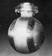
Projectors
The QB projector is a spherical hydrophone mounted on the lower end of the
starboard training shaft. One face contains
rochelle salt crystals, which change shape
when a sound wave strikes this face of the
projector. The other side is empty.
The JK/QC combination projector is
mounted portside. The JK face is just like
QB. The QC face contains small nickel
tubes, which change size when a sound wave
strikes this face. (The NM projector,
mounted on the hull centerline in the forward trim tank, is used only for echo
sounding.)
Change in shape of the salt crystals (QB,
JK) or in the size of the metal tubes (QC,
NM) generates a small electric current in
connecting cables.
Receiver-amplifiers
In the receiver-amplifier, the small electric
current is strengthened and changed so that
it is heard as sound in the phones or speaker.
Two receiver-amplifiers, QB and JK/QC,
are in the conning tower. There is also a
receiver-amplifier in the forward torpedo
room for emergency use with either system.
Remote-control units
In the conning tower are two remote
control units, one for the QB, the other for
the JK/QC projector. These operate the
training motors, and also show the direction
in which each projector is trained.
Hoist-lower-train mechanisms
Both shafts are equipped with hydraulic
mechanisms for raising and lowering the
projectors. Training motors and reduction
gears turn the shafts and projectors. Power
is supplied by two motor generators. All
of these units are in the forward torpedo
room.
Other parts
The remaining parts of the WCA are
concerned with echo-ranging or depth
sounding. For echo-ranging there is a QB
driver and a QC driver in the forward torpedo room, and a range indicator in the
conning tower. For echo-sounding, there is
a depth indicator in the control room. (The
QC driver is also used for NM in depth
sounding.)
27
In the conning tower
The photograph below shows a WCA stack, in which five units are
grouped for efficient supersonic operation. There are separate remote-control
units for the starboard (QB) and port (JK/QC) projectors, each with its receiver-amplifier. During routine search only one type of supersonic gear is
manned. But when a contact is reported, QB is taken over by the sonar operator whose battle station is at the stack, and a second operator mans JK/QC.
Normally during an attack, QB tracks the target, while JK searches for
other ships. The range indicator is not used for listening.
28
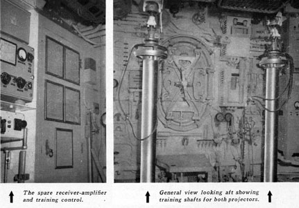
In the forward torpedo room
The photographs above give a general picture of the WCA gear in the
forward torpedo room, looking aft, with projectors raised. These are lowered by a torpedoman, operating the hoist-lower mechanisms. If for any reason, the conning tower has to be abandoned, supersonic listening can still be
carried on from the spare units in this room. These include a receiver-amplifier, which can be connected to either JK or QB, and a training control for
turning either shaft. Relative bearings can be read directly from the scale
and pointer on each hoist-train shaft. True bearings cannot be read.
Limit switches prevent training either shaft more than 2 1/4 turns, as a
protection to the cables. If you train far enough to hit one of these switches,
the training motor automatically stops. You must then train back one full
turn. Where slip rings have been installed, the training shaft can be turned
continuously in either direction without damage to the cables - eliminating
the need for limit switches.
29
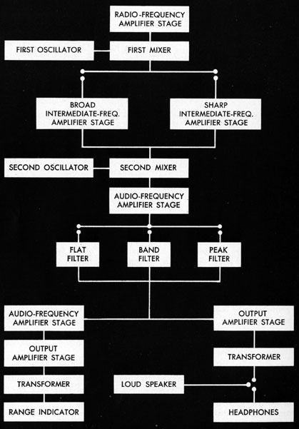
This is how the
30
receiver-amplifier works
First oscillator produces a
current whose frequency is
60 kc higher than that of the
incoming current. For example, with an incoming
current mainly of 17 kc, this
oscillator would develop 77
kc (17 plus 60).
Radio-frequency-amplifier
stage increases the strength
of the current coming from
the projector.
First mixer combines these
two currents to get a frequency that is mainly 60 kc
(77 minus 17). The frequency obtained by mixing
is always equal to the difference between the frequencies that are mixed.
BROAD Intermediate-frequency-amplifier stage strengthens a broad band of frequencies centered around 60 kc.
SHARP lntermediate-frequency-amplifier stage strengthens a narrow band of frequencies centered around 60 kc.
Second oscillator, as normally set, produces a current
whose frequency is 60,800 cycles.
Second mixer combines this
60,800-cycle current with the
amplified 60,000-cycle (60
kc) current to get a frequency that is mainly 800
cycles (60,800 minus 60,000).
Audio frequency amplifier
stage makes the current from
the second mixer stronger.
Flat filter passes frequencies
from 200 to 3000 cycles.
Audio-frequency-amplifier
stage makes the filtered current still stronger.
Output - amplifier stage
makes this current strong
enough to operate the red
light on the range indicator.
Transformer changes the
amplified current so that the
range indicator can handle it.
Range indicator. Here the
current makes a red neon
light flash. This indicator is
not used for listening.
Band filter passes frequencies from 600 to 1000 cycles.
Peak filter passes practically
only 800 cycles.
Output-amplifier stage
makes the filtered current
strong enough for the head
phones or loudspeaker.
Transformer changes this
amplified current so that the
headphones or loudspeaker
can handle it.
Loudspeaker changes the
electrical current into sound.
Headphones change the electrical current into sound.
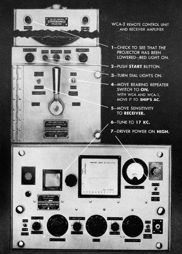
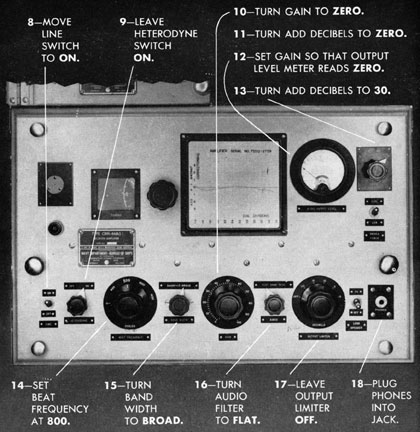
31
These are the steps to take
Heterodyne switch. When this switch is off,
the second oscillator does not work. Some
times propeller beats can be heard with it
off. But almost always you should operate
with it ON.
Output limiter cuts off part of the sound.
Once in a while, when background noise is
very high, you may use it. But to avoid
losing the target, you will almost always
keep it OFF.
32
in starting WCA listening gear
Audio-output-level meter shows the strength
of the electric current going to the head
phones or loudspeaker.
Add-decibels switch protects this meter from
breaking. Always keep it set at 30, except
when determining the proper setting for the
gain control.
Beat-frequency control. The radio technician uses this control when he adjusts the
gear. But for listening, it must always be
set at the red 800. Otherwise the target may
be lost when the PEAK filter is being used.
Driver-power switch should be left on
HIGH. It is set at LOW only when the
radioman uses the echo-ranging gear to send
underwater signals in code to another vessel.
Gain control, when turned clockwise, increases the volume of sound. There is an
other gain control on the remote-control
unit, labeled "Sensitivity." If you wish to
regulate gain from the remote-control unit,
move the sensitivity switch to REMOTE
CONTROL.
Tuning dial tunes the receiver to whatever
frequency is desired. At the same time it
automatically adjusts the first oscillator to
send whatever frequency is needed to produce 60 kc in the first mixer.
33
WCA search procedures
When you take over the watch on the WCA stack, check all controls.
If necessary, retune to 17 kc. Start with...
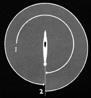
Rapid search
Swing the remote-control lever
so that the bug passes through
000 degrees and continues down the other
side to 180 degrees. Then reverse the lever
until the bug makes a complete
circle to 180 degrees. If you hear no suspicious sounds, shift to
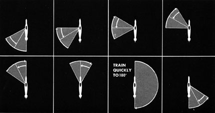
Progressive search
Reversing direction, sweep 60 degrees forward, then 30 degrees back, 60 degrees forward, 30 degrees
back - until you have crossed the bow. Then train quickly down the opposite
side to 180 degrees. Again reverse direction and sweep 60 degrees forward, 30 degrees back, 60 degrees
forward, 30 degrees back - until you have crossed the bow. Then train quickly down
the opposite side to 180 degrees. This completes one full double-cycle (720 degrees).
34
Frequency search
Every fifteen minutes during a sonar watch, you make a frequency search
to try to pick up enemy pinging. This is the sequence for a frequency search:
20 kc - one complete double cycle of progressive search.
23 kc - one complete double cycle of progressive search.
26 kc - one complete double cycle of progressive search.
29 kc - one complete double cycle of progressive search.
32 kc - one complete double cycle of progressive search.
14 kc - one complete double cycle of progressive search.
Then return to 17 kc and continue with the normal search plan.
Rate of sweep
In searching, the proper rate of sweep is somewhat less than the maximum obtained when the remote-control lever is swung all the way over. The
position of the lever to get the proper rate has to be determined by experience, since the speed steps vary on different remote-control units.
Reporting enemy echo-ranging
Sometimes a ship's pinging can be picked up before you can
hear its screws. Any ship that is pinging is out searching for submarines. Merchant vessels are not equipped for echo-ranging.
So-if you hear pinging report it at once. For example
"QB, contact, echo-ranging bearing one one ze-ro." Set your tuning dial to make the pinging come in loud and clear. Estimate
the time between pings and report whether the ship is using long
scale or short-scale pinging.
Also notice carefully whether you hear the pinging without
interruption. If it comes in for a few pings and disappears for a
minute or more, comes in again and disappears - the ship is
probably still searching. But if it comes in continuously or with
only brief interruptions, the ship has probably picked you up as a
contact and is likely to attack. This is important information and
should be reported immediately.
35
Contact !
Maybe your whole watch will be spent in just routine searching. But at
any moment you may pick up enemy propellers. Then you must quickly do
six things:
1. Immediately report the approximate relative bearing of the contact:
"QB, contact, bearing thuh-ree ze-ro ze-ro." Even if this bearing is incorrect
by 20 degrees or 30 degrees, it lets the conning officer know the general direction of the
target. If you are not sure your contact is a ship, report it anyway: "QB,
doubtful contact, bearing thuh-ree ze-ro ze-ro."
2. Reset your amplifier controls to get better bearings. Turn the gain
down to the lowest possible setting on which the target can be clearly heard.
Turn the tuning control to the highest frequency on which the target
can be clearly heard.
Shift the audio switch to BAND. If you cannot hear the target, return
the switch to FLAT.
3. Keep sweeping across the targetall the time you are making these
adjustments. Keep reading accurate bearings and reporting them. Report
relative bearings, but note the true bearing at the same time. If your submarine changes course, you can maintain contact with the target by following its true bearing during the turn. Get in the habit of noticing the true
bearing every time you read and report a relative bearing.
4. Identify the target. Describe its screws as heavy or light, slow or
medium or fast. Tell what type of ship it is. "QB, bearing thuh-ree thuh-ree
fo-wer. Heavy, slow screws. Sounds like a tanker."
5. Take a turn count and report the number of rpm. Whenever the target's speed changes, report that fact at once: "QB, bearing thuh-ree fo-wer
niner. Heavy screws speeding up." Then get the new turn count and report
the rpm.
6. Try new filter settings from time to time. If you are on BROAD-BAND, shift to BROAD-PEAK and then to SHARP-PEAK. Be ready to
shift back instantly if on the new setting you lose the target. When you
change filters, you may have to change your gain setting. But keep the gain
as low as possible at all times.
36
Using tuning, gain, and filters to narrow the target
These three controls must work as a team. They must be handled with
skill and with a complete understanding of the way they work together.
Tuning high. As the frequency of a sound increases, a hydrophone becomes
more and more directional. That is, it picks up sounds over a narrower arc.
So it is good practice to take the bearings of a target with the tuning dial
set high. Remember, however, that the attenuation is greater at higher frequencies. So if you turn the tuning knob too far, you may not be able to hear
the target at all. But always track a target at the highest frequency on which
it can be heard.
Gain low. After contact, keep your gain as low as possible. This will make
the target's screws stand out from the background noise. Also, because low
gain narrows the arc over which you hear the target sounds, you will get
better bearings.
Filters help by cutting out most of the background noise, allowing mainly
the screw sounds to come through. Sweeping a narrower arc of noise gives
more accurate bearings. Below is the order in which you are most likely to
use these filters.
Because this combination gives
a wide listening arc, it is good for
searching, but poor for getting
bearings.
Shift to BAND as soon as you
can after contact. It gives better
bearings.
PEAK narrows the arc considerably. It gives even better bearings.
This is the best combination of
all. Reach it, if possible, during an
approach.
37
Accurate and continuous bearings
Accurate bearings must be continuously supplied to the conning officer.
With some experience, you will learn to get accurate bearings if you follow the proper procedure.
Keep crossing the target completely. Sweep all the way through the
arc of propeller noise. Continue until it dies out completely. Then reverse
direction and sweep through until it dies out on the other side.
Read when sweeping from bow through stern. As quickly as possible
determine which way the target is moving. Then read the bearing on the
sweep that goes from the target's bow to the target's stern.
Read the bearing at maximum loudness. Usually you can determine
easily a point of maximum loudness. This is the bearing. If the sound is of
equal loudness over a wide are, adjust tuning, gain, and filters to narrow it
enough to give a distinct maximum.
Securing WCA gear
When your submarine surfaces, you will continue searching. While it is
running at a slow speed, you will be able to listen efficiently. But at higher
speeds the noise becomes so great that you will have to report to the conning officer: "QB, listening conditions poor." Probably you will then be ordered to secure the gear. Here is the way to secure:
1. Bring the bug either to 000 degrees or 180 degrees, whichever is required by
the cable arrangement on your ship. (Ask the radio technician.)
2. Unplug the headphones and hang them up carefully.
3. Push the STOP button on the remote-control unit; the training-motor generator light will go out.
4. Turn the line switch on the receiver-amplifier OFF.
5. The conning officer will order a torpedoman in the forward
torpedo room to raise the projectors. Watch the green light
in the upper right-hand corner of the remote-control unit.
When it glows, you know that the projector has been raised.