7G1. Description of the lower telescope system
into various assemblies. The lower telescope system
is divided into two parts, namely:
1. Part I: First, second, and third inner tube section assembly.
2. Part II: Eyepiece skeleton assembly.
a. " "
Eyepiece box and miscellaneous assemblies.
b. " "
Four packing gland assemblies.
c. " "
Eyepiece window assembly.
d. " "
Bottom plug assembly.
e. " "
Focusing knob assembly.
f. " "
Rayfilter housing, and plate assembly.
g. " "
Rayfilter eye buffer, blinder, and stowage case assemblies.
h. " "
Variable density polaroid filter assembly.
i. " "
Training handle assemblies (left and right).
j. " "
Hoisting yoke assembly (electric and hydraulic).
The lower telescope system comprises numerous assemblies end is divided principally
to permit familiarization as to nomenclature,
description, disassembly, and reassembly. It
is composed of two lenses and a dioptric prism,
namely: A lower objective lens air-space doublet,
and eyepiece prism (dioptric prism), and an
eyepiece lens doublet.
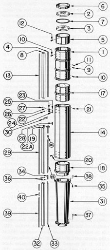
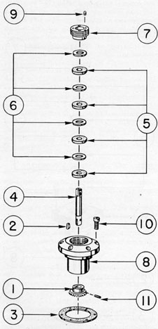
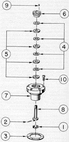
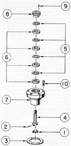
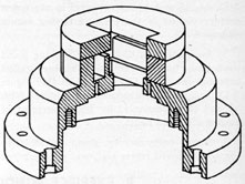
7G2. Description of Part I. The first, second, and
third inner tube section assembly is shown
in Figure 7-10. All bubble numbers in Sections
7G2, 3, and 4, refer to Figure 7-10 unless otherwise specified.
415
Ill. No.
Drawing Number
Num- ber Re- quired
Nomenclature
1
P-1484-3
1
Third inner tube section
2
P-1475-9A
1
Lower objective lens crown element
3
P-1475-9B
1
Lower objective lens flint element
4
P-1482-5
1
Head prism drive shaft section continuation
5
P-1484-1
1
Lower objective lens mount
6
P-1484-2
1
Lower objective lens clamp ring
7
P-1484-4
1
Lower objective lens spacer ring
8
P-1497-1
1
Wave guide section continuation
9
P-1506-23
4
Lower objective lens mount lockscrews
10
P-1506-25
48
Third inner tube section lockscrews, upper and lower parts
11
P-1506-26
1
Lower objective lens mount axial alignment lockscrew
12
P-1506-27
4
Lower objective lens clamp ring lockscrews
13
P-1523-8
1
Lower air line section continuation
14
P-1485-4
1
Second inner tube section
15
P-1482-5
1
Head prism drive shaft section continuation
16
P-1482-7
1
Head prism drive shaft rubber noise eliminator
17
P-1485-1
1
Second inner tube section upper end coupling
18
P-1487-2
1
Reducing coupling
19
P-1491-1
1
Wave guide section continuation
20
P-1506-23
24
Second inner tube section lower part lockscrews
21
P-1506-24
24
Second inner tube section upper part lockscrews
22
P-1506-58
2
Waveguide clamp, bracket lockscrews
22A
P-1513-8
1
Head prism drive shaft guide (soldered)
23
P-1523-1
1
Waveguide clamp plate
24
P-1523-1A
2
Waveguide clamp plate pins
25
P-1523-2
1
Waveguide clam bracket
26
P-1523-3
2
Waveguide clamp plate adjustment screws
27
P-1523-4
2
Waveguide clamp plate adjustment screw locknuts
28
P-1523-5
1
Air line strap (soldered)
29
P-1523-8
1
Lower air line section continuation
30
P-1523-10
1
Tape strap (soldered)
Ill. No.
Drawing Number
Num- ber Re- quired
Nomenclature
31
P-1490-1
1
First inner tube section
32
P-1497-1
1
Waveguide section continuation
33
P-1500-4
1
Head prism drive shaft section
34
P-1505-2
1
Head prism drive shaft universal coupling
35
P-1506-28
6
First inner tube section lockscrews, upper part
36
P-1506-100
2
Head prism drive universal coupling taper pins
37
P-1506-112
1
First inner tube section & eyepiece skeleton dowel pin
38
P-1506-114
1
First inner tube section and reducing coupling alignment dowel pin
39
P-1523-8
1
Lower air line section continuation
40
P-1523-9
1
Air line coupling (soldered)
a. Third inner tube section. The third
inner tube section (1) is identical to the seventh
inner tube section (79, Figure 7-6) and should
be referred to under Section 7F1, Part I. The
upper and lower part of this inner tube section
is a push fit on the lower alignment support
section of the fourth inner tube section lower
end coupling (40, Figure 7-7) and the upper
alignment support section of the second inner
tube section upper end coupling (17). The
upper and lower parts are each secured to their
couplings with 24 lockscrews (21 and 20). This
inner tube section carries the lower objective lens
elements (2 and 3) in a mount (5) with a spacer
ring (7), a clamp ring (6), and its lockscrews
(12). The mount is secured with four lockscrews
(9).
1. Lower objective lens. The lower objective lens (2 and 3) is made of two optical elements. It consists of a double convex crown
element separated with a spacer ring (7) from a
divergent meniscus flint element, forming an
air space doublet. Both the crown and flint
elements have a flat 50 degrees minor chord section
ground off, similar to the upper objective lens.
It is mounted in the lower objective lens mount
(5) and is secured in the mount with a clamp
ring (6). The clamp ring is secured in the mount
with four lockscrews (12).
416
2. Lower objective lens mount. The lower
objective lens mount (5) carries the lower objective lens (2 and 3) separated with a spacer ring
(7). The mount is identical to the upper objective
lens mount (82, Figure 7-6). Refer to the upper
objective lens mount (82) of Section 7F1
Part I. The mount slides in the third inner tube
section and is secured at the correct focal
distance at the factory. It is secured with
four lockscrews (9) after adjustment.
3. Lower objective lens spacer ring. The
lower objective lens spacer ring (7) is placed
between the crown and flint elements. Refer,
to the upper objective lens spacer ring (84,
Figure 7-6) of Section 7F1, Part I, as it is
identical in design and purpose.
4. Lower objective lens clamp ring. The
lower objective lens spacer ring (6) clamps
the lower objective lens (2 and 3) to the shoulder
of the mount with sufficient tension to hold
it there after the insertion of four lockscrews
(12). Refer to the upper objective lens clamp
ring (84, Figure 7-6) of Section 7F1 Part I,
as it is identical in design.
5. Head prism drive shaft section continuation. The head prism drive shaft section
continuation (4) is an extension of the head
prism drive shaft section (61, Figure 7-6)
of the eighth inner tube section (60). This shaft
continuation extends downward through clearance holes in the four bearing flanges of the
third inner tube section (1) to the left of the
rectangular waveguide slots.
6. Waveguide section continuation. The
waveguide section continuation (8) is an extension of the waveguide section (7, Figure 7-6)
of the fifth reduced tube section (1). This
extension extends the entire length of the third
inner tube section and fits in the four rectangular
slots in its bearing flanges.
7. Lower air line section continuation.
The lower air line section continuation (13)
is an extension of the lower air line section
(34, Figure 7-7) of the lower part of the fifth
inner tube section (19). This continuation
extends the entire length of the 3rd inner tube
section (1).
b. Second inner tube section. The second
inner tube section (14) is made of the same
Figure 7-10. Lower telescope system assembly,
Part I.
material and design as the eighth inner tube
section (60, Figure 7-8) except that it has an
overall length of 21.500 inches. Its upper part
is secured to the lower alignment support
section of the second inner tube section upper
end coupling (17) while at its lower part it is
secured to the upper alignment support section
417
of the reducing coupling (18). The upper and
lower part of this inner tube section are each
secured to the above couplings with 24 lockscrews
(21 and 20).
1. Second inner tube section upper end
coupling. The second inner tube section
upper end coupling (17) is identical to the
eighth inner tube section lower end coupling
(63, Figure 7-6). This upper end coupling forms
a joint between the lower part of the third inner
tube section and the upper part of the second
inner tube section.
2. Head prism drive shaft section continuation. The head prism drive shaft section
continuation (15) is an extension of the head
prism drive shaft section (61, Figure 7-6) of
the eighth inner tube section (60). This shaft
continuation extends the entire length of the
second inner tube section (14). One head prism
drive shaft noise eliminator (16) is placed on the
shaft continuation and is located in the central
part of the second inner tube section (14). The
lower end of this shaft continuation is undercut
to receive the upper part of the head prism
drive shaft universal coupling (34) which is
secured with a taper pin (36). One head prism
drive shaft guide (22A) is located in the central
part of the second inner tube section to support
the shaft continuation. It is soldered to the
flat 50 degrees minor chord wall of this inner tube
section.
3. Lower air line section continuation.
The lower air line section continuation (29)
is an extension of the lower air line section
(34, Figure 7-7) of the fifth inner tube section
(19). This continuation extends the entire
length of the second inner tube section (14).
It is soldered to an air line coupling (40) at
the upper part of the first inner tube section
(31). It is secured to the second inner tube
section (14) with a soldered airline strap (28)
located in the central part.
4. Waveguide clamp bracket. They waveguide clamp bracket (25) is secured to the upper
part of the second inner tube section (14) flush
with its upper face. The clamp bracket is
retained on the flat 50 degrees minor chord wall with
two lockscrews (22). Refer to the waveguide
clamp brackets (73, Figure 7-6) of the eighth
inner tube section (60) as the waveguide clamp
plate (23), its pins (24), two waveguide clamp
plate adjustment screws (26) and screw locknuts (27) are identical in purpose and function.
5. Tape strap. The tape strap (30) is soldered
to the periphery of the second inner tube section
(14) and is located in the central part. It is
placed in the vertical centerline of the tape
slots of the bearing flanges. This provides
vertical guidance to the change of power shifting
wire tapes (35, Figure 7-11).
6. Reducing coupling. The reducing coupling (18) is identical to the eighth inner tube
section reducing coupling (64, Figure 7-6),
with some exceptions. The reducing coupling
is reversed, which necessitates various changes
in the bearing flange, such as the various clearance holes and tape slots.
a) Two shifting wire tape slots are located
in the flange to the right of the rectangular
waveguide slot.
b) The clearance hole located to the left
of the rectangular slot is provided for the lower
part of the head prism drive shaft section continuation (15).
c) An air line clearance hole is provided for
the lower air line section continuation (29),
located on the left side of the rectangular wave
guide slot.
d) The relative position of six tapped holes
and one dowel pin hole in the bearing flange are
changed.
Refer to the eighth inner tube section reducing coupling (64, Figure 7-6) of Section
7F1, Part I, for detail concerning the alignment
support sections. The upper alignment support
section is secured in the lower part of the
second inner tube section with 24 lockscrews
(20).
c. First inner tube section. The first
inner tube section (31) is made of cast phosphor
bronze material with an overall length of 18.970
inches. It is provided with an upper bearing
flange and a lower flange, with the thickest
part of the offset provided with a rectangular
waveguide slot in similar manner to the first
reduced tube section (51, Figure 7-6). The upper
flange is provided with six clearance holes and
an inserted dowel pin (38), and is secured to the
418
bearing flange of the second inner tube section
reducing coupling with six lockscrews (35).
The dowel pin (38) is installed to reestablish
the factory alignment upon reassembly. Refer
to the reducing coupling for the location of the
head prism drive shaft section (33), the clearance holes in both flanges, the lower air line
clearance holes, and the shifting wire tape
slots in the upper flange.
The lower flange is provided with seven
tapped holes for lockscrews (35) and a dowel
pin hole for the insertion of a dowel pin (37).
Two cored rectangular slots are provided 180 degrees
apart at right angles to the rectangular waveguide slot. The slot on the right side provides
clearance for the power shifting wire tapes,
while the slot on the left side serves no particular
purpose other than to provide the flange with a
symmetrical design.
The periphery of this reduced tube section
tapers inward from the upper bearing flange
down to its lower flange. The upper part is
bored straight a sufficient distance to allow
for the undercut alignment support section of
the reducing coupling (18). The lower part is
provided with an undercut alignment support
section, which is a sliding fit in the counterbored
section in the upper part of the eyepiece skeleton
(42, Figure 7-11). The bore is tapered from the
straight bored section in the wiper part, in
similar manner to the periphery, maintaining
a uniform wall thickness to the lower flange.
The inside shoulder of the lower flange bore is
chamfered. The tapered bore is provided with
anti-reflection threads. The wall of this inner
tube section is tapered to conform to the convergence of the marginal or oblique cone of light
rays extending downward from the lower objective lens (2 and 3).
The upper part of the head prism drive shaft
universal coupling (34) couples with the stub
section of the lower part of the head prism drive
shaft section continuation (15), and is secured
together with a taper pin (36) at the upper
part of the first inner tube section (31) . The lower
part of the universal coupling couples with
the head prism drive shaft section (33) and is
secured together with a taper pin (36).
The lower part of the lower air line section
(39) is coupled to a 2-foot air line section by
means of an air line coupling (40). Both the
11-foot and 2-foot sections are soldered to the
coupling. The lower part of the air line section
is secured in the large flange of the eyepiece
skeleton (42, Figure 7-11).
7G3. Disassembly of Part I. The lower telescope
system assembly Part I is disassembled in the
following manner:
1. Separate the third inner tube section
(1) from the second inner tube section upper
end coupling (17). Remove the 24 lockscrews
(10) from the lower part of the third inner
tube section. These lockscrews are unscrewed
from tapped holes in the upper part of the second
inner tube section upper end coupling, and
carried out of countersunk clearance holes in
the lower part of the third inner tube section.
Remove the third inner tube section with the
assembled lower objective lens (2 and 3), the
lower objective lens mount (5), the lower objective lens clamp ring (6), its lockscrews (12),
the lower objective lens spacer ring (7), and the
lower objective lens mount lockscrews (9).
2. Remove the four lockscrews (9). These
lockscrews are unscrewed from the tapped holes
in the lower objective lens mount (5) and carried
out of countersunk clearance holes in the third
inner tube section.
3. Place a special lower objective lens
mount removal jig in the holes provided in the
lower part of the lower objective lens mount
(5), to allow the lower objective lens mount
to be removed.
4. Remove the four lower objective lens
clamp ring lockscrews (12). These lockscrews
are unscrewed from tapped holes in the lower
objective lens clamp ring (6) and carried out
of countersunk clearance holes in the objective
lens mount (5).
5. Remove the lower objective lens clamp
ring (6), sliding it out of the lower objective
lens mount (5).
6. Place the lower objective lens mount
(5) with the upper face downward, resting
the flint element of the lower objective lens
(2) on a special padded wooden block (Figure
7-9). The mount will slide down over the
padded block with the lower objective lens and
419
spacer ring (7) remaining on the padded portion
of the block.
7. Wrap the crown and the flint elements
(2 and 3) of the lower objective lens in clean
lens tissue and store them in a dry container to
prevent scratches and breakage.
8. Remove the two lockscrews (22) from the
waveguide clamp bracket (25). These lockscrews
are unscrewed from tapped holes in the upper
part of the second inner tube section (14)
flat 50 degrees minor chord wall and the lower alignment support section of the second inner tube
section upper end coupling (17).
9. Separate the second inner tube section
upper end coupling (17) from the second inner
tube section (14). Remove the 24 lockscrews
(21) from the upper part of the second inner
tube section. There lockscrews are unscrewed
from tapped holes in the lower alignment
support section of the second inner tube section
upper end coupling, and carried out of countersunk clearance holes in the upper part of the
second inner tube section. Remove the coupling
from the upper part of the second inner tube
section.
10. Separate the second inner tube section (14)
from the upper part of the reducing coupling (18).
Remove the 24 lockscrews (20) from the lower
part of the second inner tube section. These
lockscrews are unscrewed from tapped holes in
the upper alignment support section of the
reducing coupling and carried out of countersunk clearance holes in the lower part of the
second inner tube section. Remove the reducing
coupling and the attached first inner tube section from the lower part of the second inner tube
section.
11. Separate the lower part of the reducing
coupling (18) from the upper part of the first
inner tube section (31). Remove the six lockscrews (35) from the, upper flange of the first
inner tube section. These lockscrews are unscrewed from tapped holes in the reducing
coupling flange and carried out of clearance holes
in the upper flange of the first inner tube section.
Remove the reducing coupling from the upper
flange of the first inner tube section.
7G4. Reassembly of Part I. The lower telescope
system, Part I is reassembled in the following
manner:
1. Circular brushes must be used with a
cleaning solvent followed with a filtered air line
hose, Brush and blow out all internal surfaces
of the inner tube sections, couplings, lens mounts,
and clamp rings of Section 7G3.
2. Reassemble the reducing coupling (18)
in the upper flange of the first inner tube section (31). The alignment dowel pin (38) of the
first inner tube section upper flange should
engage in a reamed hole in the lower flange of
the second inner tube reducing coupling to reestablish the factory alignment. Secure them
together by the insertion of six lockscrews (35).
These lockscrews are inserted in clearance holes
in the upper flange of the first inner tube section and screwed into tapped holes in the lower
flange face of the reducing coupling.
3. Reassemble the lower part of the second
inner tube section (14) on the upper alignment
support section of the reducing coupling (18).
Secure the coupling to the inner tube section
with 24 lockscrews (20). These lockscrews are
inserted in countersunk clearance holes in the
lower part of the second inner tube section and
screwed into tapped holes in the upper alignment support section of the reducing coupling.
4. Reassemble the lower part of the second
inner tube section upper end coupling (17) in
the upper part of the second inner tube section
(14). Secure the coupling of the inner tube section with 24 lockscrews (21). These lockscrews
are inserted in countersunk clearance holes in
the upper part of the second inner tube section
and screwed into tapped holes in the lower alignment support section of the second inner tube
section upper end coupling.
5. Reassemble the waveguide clamp bracket
(25) to the upper part of the second inner tube
section on the flat 50 degrees minor chord wall and
secure it with two lockscrews (22). These lockscrews are inserted in countersunk clearance
holes in the bracket and screwed into tapped
holes in the upper part of the second inner tube
section and lower alignment support section of
the second inner tube section upper end coupling.
6. Clean the lower objective lens (2 and 3)
in similar manner to that noted under Step, 9
of Section 7F4.
7. Place the crown element of the lower objective lens (2) on the padded wooden block
420
(Figure 7-9) with the longest radius of this element lying on its padded surface.
8. Place the lower objective lens spacer ring
(7) with the filed flat radius facing downward.
9. Place the flint element of the lower objective lens (3) on the lower objective lens spacer
ring with the concave surface resting on the
lower objective lens spacer ring. Line up the
irregular circumference of the lenses with
the spacer ring.
10. Place the lower objective lens mount (5)
over the assembled lower objective lens (2 and
3) and the padded wooden block. Turn the
complete assembly with the padded block over
so that the flint element (3) of the lower objective lens is resting on the shoulder seat in the
lower objective lens mount (5).
11. Place the lower objective lens clamp ring
(6) in the lower objective lens mount (S) with
the flat 50 degrees minor section having a slight radius
resting against the crown element face. Secure
the upper objective lens clamp ring with four
lockscrews (12).
12. Place the assembled lower objective lens
mount (5) in the third inner tube section (1) with
the lower objective lens clamp ring (6) facing
upward.
13. Insert one lockscrew (9), screwing it
temporarily into the tapped hole in the lower
objective lens mount (5), until after the reassembly of the third inner tube section (1) to the
second inner tube section upper end coupling
(17).
14. The four lower objective lens mount lockscrews (9) are not inserted in the lower objective
lens mount until after final collimation. Place
these lockscrews in a small box until ready for
securing.
15. Reassemble the lower part of the third
inner tube section (1) on the upper part of the
second inner tube section upper end coupling
(17). Secure the coupling to the inner tube
section with 24 lockscrews (10). These lockscrews
are inserted into countersunk clearance holes in
the lower part of the third inner tube section
and screwed into tapped holes in the upper alignment support section of the second inner tube
section upper end coupling.
16. Place a canvas boot over the upper end of
the third inner tube section (1) and over the
lower flange of the first inner tube section (31)
to prevent dirt and dust settling on the lenses
and inner surface of the cleaned lenses and
inner tube sections.
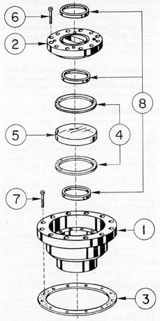
H. EYEPIECE SKELETON ASSEMBLY
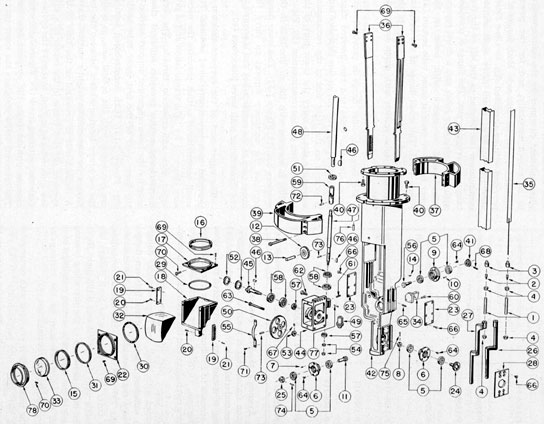
7H1. Description of the eyepiece skeleton assembly. Figure 7-11 shows the eyepiece skeleton
assembly. All bubble numbers in Sections 7H1,
2, and 3, refer to Figure 7-11 unless otherwise
specified.
Ill. No.
Drawing Number
Num- ber Re- quired
Nomenclature
1
P-1183-9
2
Shifting wire spindles
2
P-1133-10
2
Shifting wire clamps
3
P-1133-11
2
Shifting wire clamp nuts
4
P-1133-12
4
Shifting wire spindle adjusting nuts
5
P-1160-1
2
Ball bearings for rayfilter drive gear
2
Ball bearings for eyepiece prism shift gear
2
Ball bearings for training handle rack gear (right)
Ill. No.
Drawing Number
Num- ber Re- quired
Nomenclature
6
P-1166-2
1
Ball bearing housing for right training handle rack gear
1
Ball bearing housing for rayfilter drive gear
7
P-1160-2A
2
Dowel pins for rayfilter drive gear ball bearing housing
8
P-1160-4
1
Retaining collar, right training handle rack gear
9
P-1160-9
1
Ball bearing housing for eyepiece prism shift gear
10
P-1160-9A
2
Dowel pins for eyepiece prism shift gear ball bearing housing
11
P-1161-3
1
Rayfilter drive gear
421
Ill. No.
Drawing Number
Num- ber Re- quired
Nomenclature
12
P-1161-5
2
Eyepiece prism actuating gears
13
P-1161-6
2
Eyepiece prism actuating gear shafts
14
P-1163-11
1
Eyepiece prism shift bevel gear key
15
P-1173-3
1
Eyepiece lens clamp ring
16
P-1173-4
1
Eyepiece prism upper clamp ring
17
P-1173-5
1
Eyepiece prism upper retaining plate
18
P-1173-7
1
Eyepiece prism mount
19
P-1173-7A&B
8
B 2 Eyepiece prism mount stem gear racks
20
P-1173-7C
5
Eyepiece prism mount stem gear rack lockscrews
21
P-1173-7A1
4
Eyepiece prism mount stem gear rack dowel pins
22
P-1173-8
1
Eyepiece prism front retaining plate
23
P-1177-7
2
Counterweight strap retaining plates
24
P-1318-1
1
Training handle rack gear and shaft
25
P-1318-8
1
Rayfilter drive male coupling half section
26
P-1403-3
1
Power shifting rack right
27
P-1403-4
1
Power shifting rack left
28
P-1409-1
1
Retaining plate for power shift racks
29
P-1417-2
1
Nipper eccentric eyepiece prism centering ring
30
P-1417-3
1
Front eccentric eyepiece prism centering ring
31
P-1417-4
1
Eyepiece prism front clamp ring
32
P-1475-10
1
Eyepiece prism
33
P-1475-11
1
Eyepiece lens
34
P-1482-2
1
Spiral pinion gear shaft bracket
35
P-1482-6
2
Shifting wire tapes
36
P-1494-1
2
Counterweight straps
37
P-1494-2
1
Counterweight half
38
P-1494-3
6
Counterweight lockscrews
39
P-1494-4
1
Counterweight half
40
P-1495-5
14
Eyepiece skeleton and eyepiece box lockscrews and eyepiece skeleton and first inner tube section lockscrews
41
P-1495-9
1
Eyepiece prism shift bevel gear
42
P-1496-1
1
Eyepiece skeleton
Ill. No.
Drawing Number
Num- ber Re- quired
Nomenclature
43
P-1497-1
1
Waveguide section continuation
44
P-1499-1
1
Spiral drive housing
45
P-1500-1
1
Spiral bull gear shaft
46
P-1500-2
3
Spiral pinion gear key, spiral bull gear key, and head prism drive universal coupling key
47
P-1500-3
1
Spiral pinion gear shaft
48
P-1500-4
1
Head prism drive shaft section continuation
49
P-1500-5
1
Spiral pinion gear
50
P-1500-6
1
Spiral bull gear
51
P-1500-7
1
Large spiral drive housing ball bearing clamp ring
52
P-1500-8
2
Small spiral drive housing ball bearing clamp rings
53
P-1500-9
1
Spiral bull gear retaining nut
54
P-1500-10
2
Spiral pinion gear thrust nuts
55
P-1500-11
1
Spiral bull gear guard
56
P-1502-9
1
Eyepiece prism shift gear
57
P-1505-3
2
Spiral bull gear and spiral pinion gear shaft small ball bearings
58
P-1505-4
4
Spiral bull gear and spiral pinion gear shaft large ball bearings
59
P-1505-8
1
Head prism drive shaft universal coupling
60
P-1506-29
3
Spiral pinion gear shaft bracket lockscrews
61
P-1506-3
1
Spiral drive housing outer ball bearing clamp ring lockscrew
62
P-1506-35
3
Spiral drive housing short lockscrews
63
P-1506-36
2
Spiral drive housing long lockscrews
64
P-1506-37
12
Ball bearing housing lockscrews
65
P-1506-38
2
Eyepiece prism actuating gear shaft lockscrews
66
P-1506-39
20
Counterweight strap and shifting rack retaining plate lockscrews
67
P-1506-43
1
Spiral bull gear retaining nut lockscrew
68
P-1506-45
1
Eyepiece prism shift bevel gear lockscrew
69
P-1506-48
16
Counterweight strap, also upper and front eyepiece prism retaining plate lockscrews
422
Ill. No.
Drawing Number
Num- ber Re- quired
Nomenclature
70
P-1506-49
2
Eyepiece lens clamp ring, and eyepiece prism upper clamp ring lockscrews
71
P-1506-59
2
Spiral bull gear guard lockscrews
72
P-1506-100
1
Head prism drive shaft universal coupling taper pin
73
P-1506-106
2
Spiral pinion gear and shaft, and spiral bull gear and shaft taper pins
74
P-1506-110
1
Rayfilter drive male coupling half section taper pin
75
P-1506-111
1
Right training handle rack gear retaining collar taper pin
76
P-1506-112
2
Eyepiece box and eyepiece skeleton alignment dowel pins
77
P-1506-118
2
Spiral drive housing dowel pins
78
P-1511-2
1
Eyepiece lens mount
a. Eyepiece skeleton frame. The eyepiece
skeleton frame (42) is made of cast phosphor-bronze material with an over-all length of 22.747
inches. It is cast with various cored projections
and recesses to accommodate the eyepiece drive
mechanism, rayfilter drive mechanism, power
shifting mechanism and the prism tilt mechanism.
The upper part of the eyepiece skeleton is
provided with small and large shoulder flanges
with sufficient bearing surface between flanges
to carry the assembled halves of the
counter
weight (37 and 39) in the optical centerline.
The outer circumferences of both flanges are
eccentric with the optical axis 0.125 inch. defer
to the offset provision in the preceding bearing
flanges of the inner tube section couplings, as it
offers the same provision for the rectangular
waveguide section continuation (43).
The small flange is provided with rectangular
slots 180 degrees apart and perpendicular to the rectangular waveguide slot. The slots of the small
flange provide the necessary clearance for the
counterweight straps (36) while the right rectangular slot also furnishes clearance for the
power shifting wire tape (35). The elongated
slots in the large flange provide clearance for
the assembly of the counterweight straps for
their attachment to the counterweight, also to
allow sufficient clearance for the counterweight
to be moved vertically, and for the power
shifting tape on the right side. Both flanges are
provided with an elongated slot, to allow clearance for the head prism drive shaft section
continuation (48) located to the left of the rectangular waveguide slot. The flange is provided
with seven clearance holes and a dowel reamed
hole located to match with holes in the
lower flange of the first inner tube section (31,
Figure 7-10). The small flange of the eyepiece
skeleton is secured to the lower flange of the
first inner tube section with seven lockscrews
(40).
The large shoulder flange is provided with
seven clearance holes and two inserted alignment dowel pins (76). An air line clearance hole
is located on the right side of the rectangular
waveguide slot to carry the lower part of the
lower air line section continuation (39, Figure
7-10). It matches with the air line hole in the
eyepiece box (11, Figure 7-12). This lower flange
provides the necessary support to carry the
upper part of the eyepiece box and is secured to
the above flange with seven lockscrews (40).
The upper part of the eyepiece skeleton is
provided with two counterbored sections. The
small counterbored section provides the necessary clearance for light transmission and is provided with anti-reflection threads. The large
counterbored section provides sufficient clearance for the lower alignment support section of
the lower part of the first inner tube section
(31, Figure 7-10). Both counterbored sections
are concentric with the optical axis, as is also
the periphery bearing surface between the two
flanges for the counterweight's vertical travel.
A reamed hole is provided in the base of the
eyepiece skeleton frame in the center of a shallow counterbored section, to receive the eyepiece
skeleton centering screw (24, Figure 7-12) which
extends upward from the eyepiece box base.
The centering screw stabilizes the lower part of
the eyepiece skeleton in the eyepiece box.
The eyepiece drive mechanism is composed of
numerous mechanical internal parts to actuate
the eyepiece prism vertically to any diopter
423
Figure 7-11. Eyepiece skeleton assembly.
setting desired by the observer, with suitable
connecting external attachment.
b. Eyepiece prism mount, upper retaining plate, front retaining plate, and prism.
1. Eyepiece prism mount. The eyepiece prism
mount (18) provides the necessary body to
retain the eyepiece prism (32) and the eyepiece
lens (33) in a fixed vertical moving position
in the optical axis. The mount has two side
walls which prevent the eyepiece prism from
sideward motion. Each side wall is provided
with four tapped holes in the upper and front
faces to retain the eyepiece prism upper retaining
plate (17) and the eyepiece prism front retaining
plate (22) with four lockscrews each (69).
Each side wall is provided with two raised
rail bearings which are a sliding fit into the rail
bearings in each inner wall of the eyepiece skeleton frame. The mount is provided with a stem
which projects downward from the center part
of its rear body. On each side of the mount, the
stem gear racks (19) are assembled to the stem
projection. Both stem gear racks are maintained
in alignment on the stem projection with two
alignment dowel pins each (21) The left gear
rack is secured with three lockscrews (20), while
the right gear rack is secured with two lockscrews (20). The stem gear racks (19) engage
with two eyepiece prism actuating gears (12)
assembled on the eyepiece prism actuating gear
shafts (13). The shafts extend into the front of
the center wall through the bearing hole in the
gear in the center section and into the rear wall.
Each shaft is secured with a lockscrew (65)
2. Eyepiece prism upper retaining plate.
The eyepiece prism upper retaining plate
(17) is a
rectangular plate with a cylindrical projecting.
shoulder. The bore is threaded to receive an
eyepiece prism upper clamp ring (16) secured
with a lockscrew (70). The side facing toward
the front is beveled at 45 degrees to form a miter joint
with the beveled upper side of the plate.
3. Eyepiece prism front retaining plate.
The eyepiece prism front retaining plate (22) is a
rectangular plate with a cylindrical projecting
shoulder. The bore is threaded to receive an
eyepiece prism front clamp ring (31) and the
eyepiece lens mount (78).
4. Eyepiece prism. The eyepiece prism (32)
is a crown element, with a curvature ground on
the entrance and exit faces and is called a
dioptric prism or a double-convex right angle
prism, with the 45 degrees reflecting face silvered,
copper plated, and lacquered. It serves to deviate
the optical axis from a vertical to a horizontal
direction. Refer to section 7P optical system.
The eyepiece prism is retained snugly in the eyepiece prism mount (18) in the fixed central
position, with eccentric centering rings and clamp
rings. In the upper part of the mount, the eyepiece prism is secured by the application of an
upper eccentric eyepiece prism centering ring
(29) backed up with a threaded eyepiece prism
upper clamp ring (16) of nominal thickness
which is secured with a lockscrew (70). The
eccentric centering ring has a chamfer on its
lower face, to offer the curved surface of the
upper part of the eyepiece prism an equal bearing
surface. This provides a means of distributing
the pressure equally over at least 1/4 the area
of the reflecting surface, by tightening the clamp
ring. The front eccentric eyepiece prism centering
ring (30) serves at the front curved surface of
the eyepiece prism as in the upper. It is backed
up with a threaded eyepiece prism front clamp
ring (31) of nominal wall thickness.
c. Eyepiece lens mount and lens. 1. Eyepiece lens mount. The eyepiece lens mount
(78) provides an outer wall to retain the eyepiece
lens (33) in a concentric position in the eyepiece
prism front retaining plate (22). The mount is
cylindrical with the lower part undercut and
threaded to engage in the internal threads in the
eyepiece prism front retaining plate. The
threaded shoulder has sufficient length that when
the large shoulder of the mount is in a metal to
metal contact with the projecting shoulder of the
front retaining plate, it also serves to lock the
front eyepiece prism clamp ring (31). The mount
is bored with a counterbored beveled section
with a shallow shoulder remaining as the front
wall. The counter bored beveled section conforms to the angle of the eyepiece lens with the
outer surface following the same pattern to
provide a uniform wall thickness. The lower part
of the inside surface of the mount is provided
with two additional counterbored sections, one
for the periphery of the eyepiece lens (33) and
the other threaded for an eyepiece lens clamp
ring (15). The clamp ring engages in the internal
threaded section in the mount to hold the eyepiece lens and is secured with a lockscrew (70).
425
2. Eyepiece lens. The eyepiece lens (33) is
made of two optical elements. It consists of a
double-convex crown element cemented to a
double concave flint element, forming a positive
doublet. It is mounted in the eyepiece lens mount
(78) and is secured with a clamp ring (15). The
clamp ring is secured with a lockscrew (70) to
prevent its unscrewing from the mount.
d. Counterweight. The counterweight is
made up of two halves (37 and 39) of cast brass
composition material. It is provided with cored
sections, for the insertion of lead. The amount of
lead added should conform to the weight of the
assembled eyepiece prism mount. The counterweight serves to counterbalance the assembled
eyepiece prism mount, and to stabilize the mount
in any position of the allowed diopter setting
the observer desires. Both halves are assembled
together with six lockscrews (38). Body clearance
holes are provided in the counterweight half (39)
for the lockscrews (38) and their extension into
the tapped holes in the counterweight half (37).
The counterweight half section (37) is provided
with tapped holes to receive the lockscrews (38),
a rectangular waveguide slot, a radius clearance
provision cut through, and an additional part
of the rectangular slot for the head prism drive
shaft section continuation (48). An air line clearance hole is provided to the right of the rectangular waveguide slot for the lower air line
section continuation (39, Figure 7-10). Each
counterweight half is stepped 180 degrees apart, and
when assembled it forms a rectangular slot 180 degrees
apart. Each rectangular slot carries a counterweight strap (36) secured with four lockscrews
(69). The bore of the counterweight is eccentric
0.125 inch with the outer circumference. The
offset is necessary for a similar provision as indicated in each preceding bearing flange of the
inner tube section couplings. The counterweight
slides vertically on the bearing section of the
eyepiece skeleton, between the small and large
shoulder flanges.
e. Counterweight straps. The two counterweight straps (36) are made of casts phosphor-bronze material with an over-all length of 16.400
inches. The upper part of each counterweight
strap is attached to a rectangular slot in each side
of the counterweight halves. The lower part of
each is provided with a raised gear rack that
meshes with each eyepiece prism actuating gear
(12) projecting through slots in each side of the
eyepiece skeleton frame. Each strap has a pronounced inward bend, from near its upper part
to a short distance from the gear teeth in its
gear rack. The bent section is supported with a
narrow cast rib directly in the center. The
counterweight straps form linkage arms between
the counterweight and the eyepiece prism actuating gears (12). When the eyepiece prism mount
(18) is moved upward, the counterweight is
moved downward and vice versa, by means of
the actuating gears. The lower part of each
counterweight strap is retained in the vertical
groove in each side of the eyepiece skeleton
frame with counterweight strap retaining plates
(23), each secured with six lockscrews (66).
f. Eyepiece prism actuating gears, shift
gear, and shift bevel gear. 1. Eyepiece prism
actuating gears. The eyepiece prism actuating
gears (12) are perpendicular to the optical centerline of the eyepiece skeleton center framework.
Both gears are retained with two eyepiece prism
actuating gear shafts (13) and secured with lockscrews (65). The actuating gears revolve on the
shafts, and are meshed with gear racks of the
counterweight straps (36) and the gear teeth
of the eyepiece prism mount stem gear racks
(19). The right actuating gear is meshed with the
teeth of the eyepiece prism shift gear (56) in its
upper part, while in its lower part, it is meshed
with the teeth of the rayfilter drive gear (11).
2. Eyepiece prism shift gear. The eyepiece
prism shift gear (56) has gear teeth cut integral
with the shaft in its large shoulder part, while the
stub end of the shaft is supplied with a recess
keyway. The prism shift gear is mounted in two
ball bearings (5) which are mounted in a ball
bearing housing (9). An eyepiece prism shift
bevel gear (41) fits on the stub end of the shaft
over the inserted key (14), and is secured with a
lockscrew (68). The complete assembly is assembled into a clearance hole and counterbored
recess seat in the right side of the eyepiece
skeleton frame rear wall and is secured with four
lockscrews (64). Two dowel pins (10) provide a
rapid alignment reference for reassembly. The
eyepiece prism shift gear extends into the center
section of the eyepiece skeleton frame and
meshes with the right eyepiece prism actuating
gear (13) in its upper part.
3. Eyepiece prism shift bevel gear. The
eyepiece prism shift bevel gear (41) attached to
426
the stub end of the eyepiece prism shift gear
shaft (56), extends outward from the ball bearing
housing (9) and the rear wall of the eyepiece
skeleton frame. This bevel gear has a 60 degrees pitch
cone line angle, meshing with another bevel
gear having a similar pitch cone line angle. The
eyepiece prism shift mechanism bevel gear (1,
Figure 7-14), attached to the eyepiece drive
actuating shaft (4), extends inward from the eyepiece drive packing gland assembly in the eyepiece box to mesh with the eyepiece prism shift
bevel gear, with the angular axes of 120 degrees.
g. The rayfilter drive mechanism. It is composed of numerous mechanical parts forming an
internal assembly to synchronize the movement
of the rayfilter attachment with the eyepiece
drive mechanism-.
1. Rayfilter drive gear. The rayfilter drive
gear (11) has gear teeth cut integral with the
shaft in its large shoulder part. It is mounted
in two ball bearings (5) which are mounted in a
ball bearing housing (6). The rayfilter drive male
coupling half section (25) fits on the stub end of
the rayfilter drive gear shaft and is secured with a
taper pin (74). The complete assembly is assembled into a clearance hole in the right side of the
eyepiece skeleton frame front center wall, and
the flange is secured with four lockscrews (64).
Two dowel pins (7) provide a rapid alignment
reference for reassembly. The rayfilter drive gear
extends into the center section of the eyepiece
skeleton frame, and meshes with the right eyepiece prism actuating gear (12) in its lower part.
It is located 180 degrees opposite the eyepiece prism
shift gear (12). The male coupling half section
(25) serves as a thrust collar and couples with
the rayfilter drive female coupling section (1,
Figure 7-13) attached to the rayfilter drive
actuating shaft (8, Figure 7-13) extending inward from the rayfilter drive packing gland
assembly in the eyepiece box.
h. The change of power mechanism. The
change of power mechanism is composed of
numerous mechanical parts forming the internal assemblies for connection with an external
attachment for change of power.
1. Right training handle rack gear and
shaft. The right training handle rack gear and
shaft (24) has gear teeth cut integral with the
shaft in the large shoulder part. It is mounted in
two ball bearings (5) which are mounted in a ball
bearing housing (6). The stub end of the shaft
is provided with a retaining collar (8) secured to
the shaft with a taper pin (75). The retaining
collar serves as a thrust collar to establish only
sufficient clearance for its operation with the
two ball bearings.
The complete assembly is assembled into a
clearance hole and counterbored section seat in
the right side of the eyepiece skeleton frame and
is secured with four lockscrews (64). The training
handle rack gear is provided with a milled recess
in the form of an inside male coupling section.
The male coupling section is recessed to provide
clearance for the female coupling section (1,
Figure 7-16) attached to the actuating shaft
(4, Figure 7-16). The training handle rack gear
meshes with the right and left power shifting
racks (26 and 27) to provide actuation to the
power shifting racks for change of power.
2. Power shifting racks right and left. The
power shifting racks (26 and 27) are made of cast
phosphor bronze material, each rack having an
overall length of 7.375 inches. Both racks are
provided with offset arms and hubs to establish
the center axis of each hub with proper clearance
on each side of the optical centerline, and to
provide sufficient clearance for both shifting
wire spindle assemblies. The left power shifting
rack (27) is provided with gear teeth in the
lower straight section in the right side face to
mesh with the training handle rack gear (24).
The right power shifting rack (26) has gear teeth
in the lower straight section in the left side that
mesh as in the left power shifting rack.
The arm of the right power shifting rack is
offset to the right of the lower straight section
and slightly outward. The hub section is offset
to the left and slightly outward, with a reamed
hole in the center of the hub to carry the shifting
wire spindle assembly. The arm of the left power
shifting rack is offset to the right and outward.
The hub section is offset to the right and slightly
outward, with a reamed hole in the center of the
hub to carry the shifting wire spindle assembly.
Both power shifting racks are carried in the
vertical grooves in the right side of the eyepiece
skeleton frame. Both racks are, retained in the
vertical recess slots with a retaining plate (28)
and secured with eight lockscrews (66). The
retaining plate is provided with a clearance hole
in its central part to accommodate the female
427
coupling section (1, Figure 7-16) of the right
training handle packing gland assembly.
3. Shifting wire spindles. The two shifting
wire spindles (1) are made of phosphor-bronze
rod material with an overall length of 2 inches.
The outer circumference is threaded to carry
two shifting wire spindle adjusting nuts (4) on
the lower part. The upper part has a 16 degrees
countersunk section in its center axis, to receive
a 14 degrees tapered shifting wire clamp (2) and the
shifting wire clamp nut (3) on its threaded
periphery. The center axis of the spindle has a
clearance hole for the phosphor-bronze wire extension of the shifting wire tape (35). Each
shifting wire spindle fits in the reamed hole in
either power shifting rack hub section and has
an adjusting nut on its upper and lower part
in contact with the upper and lower faces of the
shifting rack hub section.
4. Shifting wire clamps. The two shifting
wire clamps (2) are made of corrosion-resisting
steel material. A clearance hole is provided
through the center axis of each, with a sawed slot
the depth of which corresponds to the length of
the tapered part. The upper part is undercut and
forms an alignment support section in the clamp
nut. The tapered slotted section when assembled
in the upper countersunk section in the spindle,
closes as the clamp nut is tightened and in this
manner clamps the phosphor bronze wire extension of the power shifting wire tape (35).
5. Shifting wire clamp nuts. The two shifting wire clamp nuts (3) are made of phosphor-bronze material. The center axis of each has a
clearance hole for the phosphor bronze wire extension of the shifting tape (35). In the upper
part a small counterbore is provided as an
alignment support section with the 1arge counterbored section threaded to engage on the threaded
periphery of the shifting wire spindles (1).
i. The prism tilt mechanism. It is composed
of numerous mechanical internal parts, to operate
the head prism for all degrees of elevation and
depression. This is accomplished with internal
connecting linkage and a suitable connecting
external attachment.
1. Spiral drive housing. The spiral drive
housing (44) is made of cast phosphor-bronze
material. This housing carries the spiral drive
mechanism and is secured to the offset section
located on the right side of the eyepiece skeleton,
with three short and two long lockscrews (62
and 63). The alignment dowel pins (77) provide
a rapid alignment reference for reassembly. The
housing is shaped like a box with two integral
projections located on the rear wall. The upper
projection carries two ball bearings (58) and
the lower carries one ball bearing (57).
2. Spiral pinion gear shaft. The spiral pinion gear shaft (47) is made of corrosion-resisting
steel material with an over-all length of 7 inches.
The upper stub section carries the lower part
of a head prism drive shaft universal coupling
(59) secured together with a taper pin (72).
The upper part of the universal coupling with a
keyseat, is a sliding fit on the lower stub section
of the head prism drive shaft section continuation (48) over an inserted woodruff key (46).
The upper part of the spiral pinion gear shaft is
supported with a bracket (34) at an angle of 9 degrees.
The bracket is secured to the rear wall of the
eyepiece skeleton with three lockscrews (60).
The lower undercut part of the spiral pinion
gear shaft extends through a large spiral drive
housing ball bearing clamp ring (51), and two
large ball bearings (58) mounted in the large
projection of the spiral drive housing (44) at a
9 degrees angle. The spiral pinion gear shaft is provided
with an inserted woodruff key (46) which extends into the spiral pinion gear keyway and
axis hole (49). The long hub of the pinion gear
is secured snugly against the center ball bearing
race with a taper pin (73). The stub section of
this shaft has a small straight shoulder and a
small threaded section. The small straight
shoulder extends into a small ball bearing (57)
mounted in the small projection of the spiral
drive housing (44) at a 9 degrees angle. Two thrust nuts
(54) engage on the threaded periphery of the
shaft, an provide a means of eliminating the
axial play of the small ball bearing (57).
3. Spiral pinion gear. The spiral pinion gear
(49) is made of corrosion-resisting steel material
with an overall length of 1.218 inches. Its center
axis is reamed to slide on the spiral pinion gear
shaft (47) with an inside keyway its entire
length. The external part is provided with a
small and large hub, separated with a shoulder.
The shoulder is provided with right-hand spiral
428
teeth, having an angle of 45 degrees to mesh with the
right-hand spiral teeth of a spiral bull gear (50)
at right angles. The small hub is undercut to
provide only a sufficient bearing contact with
the center ball bearing race of the small ball
bearing (57). The spiral pinion gear is driven by
the spiral bull gear (50) with the spiral teeth
coming in contact gradually instead of touching
across the entire face instantaneously which is a
usual procedure with spur gearing. This increases
the average number of teeth in contact and
makes the gears stronger and more quiet. The
spiral pinion gear is secured snugly against the
center ball bearing race of the lower large ball
bearing (57) with a taper pin (73).
4. Large spiral drive housing ball bearing
clamp ring. The large spiral drive housing ball
bearing clamp ring (51) is a cylindrical ring of
nominal wall thickness, threaded on its outer
circumference, to engage in the internal threaded
section in the upper part of the large projection of
the spiral drive housing (44). Two shallow slots
are provided in the upper face 180 degrees apart for
the insertion of a special wrench. This clamp ring
retains both large ball bearing races (58) against
a counterbored shoulder seat in the large ball
bearing projection of the spiral drive housing
and is secured with a lockscrew (61).
5. Spiral bull gear shaft. The spiral bull
gear shaft (45) is made of corrosion-resisting sting steel
material, with an overall length of 2.150 inches.
A large shoulder is provided with two projecting
lugs to form a male coupling section to connect
with a female coupling section (1, Figure 7-15)
of the left training handle packing gland assembly extending inward from the eyepiece box.
The main body section of this shaft fits in two
large ball bearings mounted in the outer wall of
the spiral drive housing (44). An inserted woodruff key (46), in the shaft fits into the spiral bull
gear (50) with a keyseat. A small straight
shoulder is threaded to carry a retaining nut
(53). The stub end of the shaft fits into a small
ball bearing (57) mounted in the inner wall of
the spiral drive, housing. The stub end of the
shaft extends through a clearance hole beyond
the ball bearing counterbored seat into a reamed
hole in the offset side wall of the eyepiece
skeleton.
6. Spiral bull gear. The spiral bull gear (50)
is made of phosphor-bronze material. Its center
axis has a reamed hole, and a keyseat which is a
sliding fit on the inserted woodruff key (46) and
spiral bull gear shaft (45). The external part is
provided with a short and long hub, separated
by a large shoulder. The large shoulder is provided with right-hand spiral teeth, having an
angle of 45 degrees, to mesh with the right-hand spiral
teeth of a spiral pinion gear (49). The spiral
pinion gear and the spiral bull gear have a 3 to
1 ratio. The shoulder body of the spiral bull gear
is provided with four equally spaced clearance
holes. The bull gear is placed in the cored center
section of the spiral drive housing. It is secured
to its shaft with a taper pin (73) through the
long hub, after adjustment has been made with
a retaining nut (53). The retaining nut is secured
with a lockscrew (67),
7. Small spiral drive housing ball bearing
clamp rings. The two small spiral drive housing
ball bearing clamp rings (52) are cylindrical with
nominal wall thickness, with their outer circumference threaded to engage in the internal
threaded section in the outer side wall of the
spiral drive housing (44). Each ring is provided
with two shallow slots in the outer face 180 degrees
apart for the insertion of a special wrench. The
inner clamp ring secures the large ball bearing
races against the counterbored shoulder seat in
the spiral drive housing, while the outer clamp
ring serves as a lock ring to maintain the adjustment of the inner ring.
8. Spiral bull gear guard. The spiral bull
gear guard (55) is placed over the front face of
the spiral bull gear (50) and centered. It is secured to the upper and lower walls of the spiral
drive housing (44) with two lockscrew (71). The
guard prevents the gear teeth of the spiral bull
gear from damage when removing the eyepiece
box from the eyepiece skeleton or vice versa.
7H2. Disassembly of the eyepiece skeleton assembly Part II. This procedure is performed in the
following manner:
1. Remove the eyepiece prism mount (18) by
pulling it out vertically clear of the rail bearings
in the inner side walls of the eyepiece skeleton
(42).
2. Remove the lockscrew (70) from the eyepiece prism upper retaining plate (17). This lockscrew is unscrewed from a tapped hole in the
429
eyepiece prism upper retaining plate and the
eyepiece prism upper clamp ring (16).
3. Remove the four lockscrews (69) from
the eyepiece prism upper retaining plate (17).
These lockscrews are unscrewed from tapped
holes in the upper side walls of the eyepiece
prism mount (18). Remove the eyepiece prism
upper retaining plate with the eyepiece prism
upper clamp ring (16). Remove the upper eccentric eyepiece prism centering ring (29) and
unscrew the eyepiece prism upper clamp ring
(16) from the above retaining plate.
4. Remove the assembled eyepiece lens
mount (78) with the eyepiece lens (33), eyepiece
lens clamp ring (15), and its lockscrew (70) by
unscrewing the eyepiece lens mount from the
eyepiece prism front retaining plate (22).
5. Remove the lockscrew (70) from the eyepiece lens mount (78) and the eyepiece lens
clamp ring (15). This lockscrew is unscrewed
from the tapped hole in the eyepiece lens clamp
ring and carried out of the countersunk clearance hole in the eyepiece lens mount.
6. Remove the eyepiece lens clamp ring (15)
unscrewing it from the eyepiece lens mount (78).
7. Remove the eyepiece lens (33) from the
eyepiece lens mount (78) and wrap the eyepiece
lens in clean lens tissue. Place it in a dry container to prevent scratches and breakage.
8. Use clean lens tissue to remove the eyepiece prism {32) slicing it out of the eyepiece
prism mount (18) from the upper end. Wrap the
eyepiece prism in clean lens tissue and store it
in a dry container to prevent scratches and
breakage.
9. Remove the four lockscrews (69) from
the eyepiece prism front retaining plate (22).
These lockscrews are unscrewed from tapped
holes in the front side walls of the eyepiece prism
mount (18). Unscrew the eyepiece prism clamp
ring (16) from the eyepiece prism front retaining
plate (22). Remove the front eccentric eyepiece
prism centering ring (30).
10. Remove the three lockscrews (20) from
the left prism stem gear rack (19) removing the
rack. These lockscrews are unscrewed from
tapped holes in the stem of the eyepiece prism
mount (18).
11. Remove the two lockscrews (20) from the
right prism mount stem gear rack (19) and remove the rack. These lockscrews are unscrewed
from tapped holes in the rack and carried out of
countersunk clearance holes in the eyepiece
prism mount stem (18).
12. Remove the eight lockscrews (66) from
the power shifting rack retaining plate (28).
These lockscrews are unscrewed from the center
raised portion on the power shift side of the
eyepiece skeleton. Remove the retaining plate.
13. As the power shifting rack retaining plate
(28) is removed, the power shifting racks ( 26 and
27) are removed from the right side of the eyepiece skeleton frame (42).
14. Remove the two shifting wire spindle adjusting nuts (4). Unscrew them from the lower
part of the shifting wire spindles (1) of the power
shifting racks (26 and 27). The shifting wire
spindle assemblies consist of two shifting wire
spindles (1), two shifting wire clamps (2), two
shifting wire clamp nuts (3), and four shifting
wire spindle adjusting nuts (4).
15. Remove the head prism drive shaft universal coupling taper pin (72) from the head
prism drive shaft universal coupling (59) and
the spiral pinion gear shaft (47). Remove the
head prism drive shaft universal coupling (59)
from the upper part of the spiral pinion gear
shaft (47).
16. Remove the three lockscrews (60) from
the spiral pinion gear shaft bracket (34). These
lockscrews are unscrewed from tapped holes in
the rear wall of the eyepiece skeleton frame.
Remove the spiral pinion gear shaft bracket (34)
sliding it off the upper part of the spiral gear
shaft (47).
17. Remove the three short and two long
lockscrews (62 and 63) from the spiral drive
housing (44). These lockscrews are unscrewed
from tapped holes in the left side of the eyepiece
skeleton frame. Remove the assembled spiral
drive housing from the left side of the eyepiece
skeleton frame (42).
18. The spiral drive housing (44) is disassembled by following the procedure of Steps 19
to 29 inclusive. Remove two spiral bull gear
guard lockscrews (71). These lockscrews are
430
unscrewed from the tapped holes in the front
wall of the spiral drive housing (44). Remove the
spiral bull gear guard (55).
19. Remove the spiral bull gear retaining nut
lockscrew (67). It is unscrewed from a tapped
hole in the spiral bull gear retaining nut (53).
20. Remove the spiral drive housing large ball
bearing clamp ring lockscrew (61). The lockscrew is unscrewed from a tapped hole in the
large bearing projection in the rear part of the
spiral drive housing (44).
21. Remove the taper pin (73) by driving it
out of the spiral pinion gear (49) and the spiral
pinion gear shaft (47).
22. Remove the taper pin (73) from the spiral
bull gear (50) and its shaft (45).
23. With the use of a special wrench, remove
the two spiral drive housing small ball bearing
clamp rings (52). These clamp rings are unscrewed from the left side face of the spiral drive
housing (44).
24. With the use of a special wrench, remove
the spiral drive housing large ball bearing clamp
ring (51). This ball bearing clamp ring is unscrewed from the large ball bearing projection
in the rear part of the spiral drive housing (44).
Carry the large ball bearing clamp ring off over
the spiral pinion gear shaft (47).
25. Remove the two spiral pinion gear thrust
nuts (54). Unscrew these thrust nuts from the
lower end of the spiral pinion gear shaft (47).
26. Release the spiral buff gear retaining nut
(53) and tap the spiral bull gear shaft (45) toward the left side wall in a series of steps allowing the retaining nut to touch the inner side wall
of the spiral drive housing (44) each This
procedure is followed until the retaining nut is
removed from the threaded periphery of the
spiral bull gear shaft. This method prevents the
spiral bull gear teeth from becoming damaged.
27. Tap the spiral bull gear shaft (45) out of the
spiral drive housing a center punch in the
center of the small end of the shaft. Remove
the spiral bull gear shaft with the two assembled
large ball bearings (58) and a spiral gear key
(46) remaining in the spiral bull gear shaft.
Remove the spiral bull gear (50) and the spiral
bull gear retaining nut (53) from the spiral drive
housing (44).
28. Remove the spiral pinion gear shaft (47),
pulling it out carefully from the spiral pinion
gear (49) and the small spiral pinion gear shaft
ball bearing (57). Remove the spiral pinion gear.
The large spiral pinion gear shaft bail bearings
(58) and the spiral pinion gear key (46) remain
on the shaft.
29. The spiral bull gear and the spiral pinion
gear shaft small ball bearings (57) remain in the
spiral drive housing.
30. Remove the six lockscrews (66) from each
counterweight strap retaining plate (23). These
lockscrews are unscrewed from the raised
shoulder on each side of the eyepiece skeleton.
Remove each of the retaining plates.
31. Remove the four lockscrews (69) from
the upper part of each counterweight strap (26).
These lockscrews are unscrewed from tapped
holes in the rectangular slots in each counterweight half (37 and 39). Remove each counterweight strap.
32. Remove the six lockscrews (38) from the
counterweight half (39). These lockscrews are
unscrewed from the tapped holes in the counterweight half. (37). Remove both counterweight
halves (37 and 39) from between the large and
small flanges of the upper part of the eyepiece
skeleton (42).
33. Remove the four lockscrews (64) from
the eyepiece prism shift gear ball bearing housing (9). These lockscrews are unscrewed from
the tapped holes in the counterbored section
seat in the rear wall of the eyepiece skeleton.
Remove the assembly consisting of the following: eyepiece prism shift gear ball bearing housing (9), two eyepiece prism shift gear ball
bearings (5), eyepiece prism shift gear and integral shaft (56), eyepiece prism shift bevel gear
key (14), its lockscrew (68), eyepiece prism shift
bevel gear (41), and two dowel pins (10).
34. In case the assembly is damaged or corroded, it will require disassembly. This is accomplished by following the disassembly procedure
of Steps 34 to 37 inclusive. Remove the lockscrew (68) from the eyepiece prism shift bevel
gear (41). This lockscrew is unscrewed from a
431
tapped hole in the eyepiece prism shift bevel gear
and removed from its contact in the spotted
recess in the eyepiece prism shift gear integral.
shaft (56).
35. Remove the eyepiece prism shift bevel
gear (41) from the eyepiece prism shift gear
integral shaft (56) and remove the inserted eyepiece prism shift bevel gear key (14) from the
integral shaft.
36. Remove the eyepiece prism shift gear integral shaft (56) from the center races of the
two ball bearings (5), carrying it out of the small
end of the eyepiece prism shift gear ball bearing
housing (9).
37. Remove the two eyepiece prism shift gear
ball bearings (5) from both ends of the eyepiece
prism shift gear ball bearing housing (9).
38. Remove the four lockscrews (64) from the
rayfilter drive gear ball bearing housing (6).
These lockscrews are unscrewed from tapped
holes in the counterbored raised boss face of the
eyepiece skeleton center wall. Remove the assembly consisting of the rayfilter drive ball bearing
housing (6), two rayfilter drive gear ball bearings
(5), rayfilter drive gear and integral shaft (11),
rayfilter drive male coupling half section (25),
its taper pin (74), and two dowel pins (7).
39. In case the assembly is damaged or corroded, it will require disassembly. This is
accomplished by following the disassembly procedure of Steps 39 to 42 inclusive. Remove the
taper, pin (74) from the rayfilter drive male
coupling half section (25) and the rayfilter drive
gear and integral shaft (11).
40. Remove the rayfilter drive male coupling
half section (25) from the integral shaft of the
rayfilter drive gear (11).
41. Remove the rayfilter drive gear integral
shaft (11) from the center races of two ball
bearings (5), carrying it out of the small end of
the rayfilter drive gear ball bearing housing (6).
42. Remove the two rayfilter drive gear ball
bearings (5) from both ends of the rayfilter drive
gear ball bearing housing (6).
43. Remove the four lockscrews (64) from
the right training handle rack gear ball bearing
housing (6). These lockscrews are unscrewed
from tapped holes in the counterbored seat in
the right side of the eyepiece skeleton. Remove
this assembly consisting of the right training
handle rack gear ball bearing housing (6), two
right training handle rack gear ball bearings (5),
right training handle gear and shaft (24), right
training handle rack gear retaining collar (8),
and its taper pin (75).
44. In case the assembly is damaged or corroded, it will require removal. This is accomplished by following the disassembly procedure
of Steps 44 to 47 inclusive. Remove the taper
pin (75) from the right training handle rack gear
retaining collar (8) and the right training handle
rack gear integral shaft (34).
45. Remove the right training handle rack
gear retaining collar (8) from the right training
handle rack gear integral shaft (24).
46. Remove the right training handle rack
gear and shaft (24) from the center races of the
two ball bearings (5), carrying it out from the
large shoulder flange end of the right training
handle rack gear ball bearing housing (6).
47. Remove the two training handle rack gear
ball bearings (5) from both ends of the right
training handle rack gear ball bearing housing (6).
48. Remove the two lockscrews (65) from
their contact in the spot faces in two eyepiece
prism actuating gear shafts (13). These lockscrews are unscrewed from tapped holes in a
raised shoulder on each side of the eyepiece
skeleton.
49. Remove the eyepiece prism actuating gear
shafts (13) and the eyepiece prism actuating
gears (12). The shaft and gears slide out easily.
7H3. Reassembly of the eyepiece skeleton assembly, Part II. his procedure is performed in the
following manner.
1. Place both eyepiece prism actuating gears
(12) in the center section of the eyepiece skeleton (42). Reference marks on both gears and
shaft must be noted for correct reassembly to
corresponding reference marks on the eyepiece
skeleton frame.
2. Place both eyepiece prism actuating gear
shafts (13) in the reamed holes in the center and
the rear frame wall of the eyepiece skeleton.
432
These shafts extend into the front wall, then
through the center bearing hole in each eyepiece
prism actuating gear (12) into the rear wall.
Secure the shafts with two lockscrews (65).
These lockscrews are inserted in clearance holes
and screwed into the tapped sections in each
raised shoulder on opposite sides of the eyepiece
skeleton to extend into a spotted recess in each
eyepiece prism actuating gear shaft (13).
3. Reassemble both counterweight halves
(37 and 39) on the bearing surface between the
small and large flanges of the eyepiece skeleton
(42). The cored part of each counterweight half
faces upward. Secure both halves of the counterweight together by inserting six lockscrews (38).
These lockscrews are inserted in clearance holes
in the counterweight half (39) and screwed into
tapped holes in its opposite counterweight
half (37).
4. Place each counterweight strap (36)
through each elongated slot in the large shoulder
flange of the eyepiece skeleton located 180 degrees apart.
Secure each counterweight strap to the rectangular slotted face on opposite sides of the
counterweight with four lockscrews each (69).
These lockscrews are inserted in countersunk
clearance holes in each counterweight strap and
screwed into tapped holes in the opposite
rectangular slotted faces of the assembled
counterweight.
5. Engage the lower end of each counterweight strap gear race (36) in mesh with each
eyepiece prism actuating gear (1,2) in the grooved
section between two rectangular raised bosses.
6. Reassemble the counterweight strap retaining plates (23) over each counterweight
strap (36) on the rectangular raised bosses on
opposite side walls of the eyepiece skeleton
frame. Secure each retaining plate with six
lockscrews (66). The lockscrews are inserted into
countersunk clearance holes in the retaining
plate and screwed into the tapped holes in the
rectangular raised bosses of the left and right
side-walls of the eyepiece skeleton.
7. Reassemble the eyepiece prism shift gear
ball bearings (5) into the eyepiece prism shift
gear ball bearing housing (9) from both ends.
8. Reassemble the eyepiece prism shift gear
integral shaft (56) into the center races of the
two ball bearings (5) from the small end of the
eyepiece prism shift gear ball bearing housing
(9). The shaft extends through both ball bearing
center races, with the shoulder of the eyepiece
prism shift gear a metal-to-metal contact with
the center race of the inner ball bearing.
9. Place the eyepiece prism shift bevel gear
key (14) in the keyway in the eyepiece prism
shift gear integral shaft (56).
10. Reassemble the hub end of the eyepiece
prism shift bevel gear (41) on the inserted key
(14) and the stub end of the eyepiece prism shift
gear integral shaft (56) up against its shoulder.
Secure the bevel gear to the shaft by the insertion of a lockscrew (68). This lockscrew is
screwed into a tapped hole in the hub of the
above bevel gear and extends into a spotted
recess in the stub end of the shaft (56).
11. Reassemble the eyepiece prism shift gear
mechanism assembly into the clearance hole and
the counterbored section seat in the rear wall of
the eyepiece skeleton frame. The dowel pins (10)
of the housing engage in the reamed holes in
the counterbored section seat in the eyepiece
skeleton frame. Secure the eyepiece prism shift
gear ball bearing housing (9) with four lockscrews (64). These lockscrews are inserted in
countersunk clearance holes in the housing and
screwed into tapped holes in the counterbored
section seat in the eyepiece skeleton frame.
Check the reference mark of the eyepiece prism
shift gear (56) to engage with a corresponding
reference mark on the right eyepiece prism actuating gear (12).
12. Reassemble the rayfilter drive gear ball
bearings (5) into both ends of the rayfilter drive
gear ball bearing housing (6).
13. Reassemble the rayfilter drive gear integral shaft into the center aces of the rayfilter
drive gear ball bearings (5) from the small end
of the rayfilter drive gear ball bearing housing
(6). The shaft extends through the ball bearing
races with the shoulder of the rayfilter drive.
gear (11), a metal-to-metal contact with the
inner ball bearing race.
14. Reassemble the rayfilter drive male coupling half section (25) on the stub end of the rayfilter drive gear integral shaft (11) and secure the
coupling to the shaft with a taper pin (74).
433
15. Reassemble the rayfilter drive gear mechanism assembly into a reamed hole and the raised
boss of the front center wall of the eyepiece
skeleton frame. The dowel pins (7) of the housing
engage in reamed holes in the eyepiece skeleton
frame raised boss. Secure the rayfilter drive
gear ball bearing housing (6) with four lockscrews
(64). These lockscrews are inserted in countersunk clearance holes in the housing and screwed
into tapped holes in the raised boss of the eyepiece skeleton frame front center wall. Check the
reference marks of the rayfilter drive gear (11)
to engage with a corresponding reference mark
in the right eyepiece prism actuating gear (12).
16. Reassemble the right training handle rack
gear ball bearings (5) in both ends of the right
training handle rack gear ball bearing housing
(6).
17. Reassemble the right training handle rack
gear integral shaft (24) into the center races of
the right training handle rack gear ball bearings
(5) from the large end of the ball bearing housing. The shaft extends through the center ball
bearing races with the shoulder of the right
training handle rack gear a metal-to-metal contact with the inner ball bearing race.
18. Reassemble the right training handle rack
gear retaining collar (8) to the stub end of the
right training handle rack gear integral shaft
(24), and secure the retaining collar to the shaft
with a taper pin (75).
19. Reassemble the right training handle rack
gear mechanism assembly into the bored hole
and counterbored section seat in the right side
of the eyepiece skeleton frame. Secure the right
training handle rack gear ball bearing housing
(6) with four lockscrews (64). These lockscrews
are inserted in countersunk clearance holes in
the housing and screwed into tapped holes in
the counterbored section seat in the right side
of the eyepiece skeleton frame.
20. The spiral drive housing is reassembled
by following Steps 20 to 29 inclusive. Place the
spiral pinion gear (49) between the large and
small bearing projection of the spiral drive housing (44) with the large hub of the spiral pinion
gear fitting into the large bearing projection.
21. Reassemble the spiral pinion gear shaft
(45) with two assembled large ball bearings (58)
and the inserted spiral pinion gear key (46) into
the keyseat in the spiral pinion gear (49). Push
the shaft with the key into the spiral pinion
gear keyseat and carry the stub and of the shaft
further into a spiral pinion gear shaft ball bearing (57).
22. Reassemble both spiral pinion gear thrust
nuts (54). Screw them on the lower threaded
periphery of the spiral pinion gear shaft (47).
Tighten both thrust nuts. This prevents any
axial motion of the spiral pinion gear (49) between the small spiral pinion gear shaft ball
bearings (57) and the large spiral pinion gear
shaft ball bearings (58).
23. Insert a taper pin (73) into the large hub
of the spiral pinion gear (49) and its shaft (47)
for its securement.
24. Reassemble the spiral drive housing large
ball bearing clamp ring (51), carrying it on over
the spiral pinion gear shaft (47). Screw the above
ball bearing clamp ring into the internal threaded
section of the large bearing projection, using a
special wrench. Tighten the clamp ring until no
axial motion is noticed in the spiral pinion gear
shaft (47).
25. Place the spiral bull gear (50) in the spiral
drive housing (44) with the longer hub facing
the small spiral bull gear shaft ball bearing (57).
Check the reference mark of the spiral pinion
gear (49) to make sure that the reference tooth
of this pinion gear will engage between the two
reference teeth of the spiral bull gear (50).
26. Place the spiral bull gear shaft (45) with
the assembled large spiral bull gear shaft ball
bearings (48) and the inserted spiral bull gear
key (46) through the outer wall of the spiral.
drive housing (44) in the spiral bull gear and its
keyseat (50). Place the spiral bull gear retaining
nut (54) between the hub of the spiral bull gear
and the inner wall of the spiral drive housing.
With the retaining nut held with a pair of
tweezers, the spiral bull gear shaft assembly is
pushed in to allow the inserted key (46) to
engage in the keyseat in the spiral bull gear (40).
The retaining nut is screwed on the spiral bull
gear shaft in a series of tightening steps. As the
retaining nut reaches the hub of the spiral bull
gear each time, the assembly is pushed in. The
434
pushing operation allows the retaining nut to
touch the inner wall of the spiral drive housing
each time. This procedure must be followed in
order to prevent damage to the teeth of the
spiral bull gear. Place a screw driver in one of
the spiral bull gear openings, allowing the screw
driver to touch the bottom cored surface of the
spiral drive housing. This provides an anchorage
for the bull gear, and allows the retaining nut to
be tightened without damaging the teeth of
the bull gear.
27. Insert a taper pin (73) into the hub of the
spiral bull gear (50) and its shaft (4S). Align
the retaining nut tapped hole with the spotted
recess in the spiral bull gear shaft. The retaining
nut will require a slight further tightening.
When the alignment is ascertained, insert the
spiral bull gear retaining nut lockscrew (67).
The lockscrew is screwed into a tapped hole in
the above retaining nut and extends into the
spotted recess in the spiral bull gear shaft (45).
28. Place the inner of two small spiral drive
housing ball bearing clamp rings (52) in the
internal threads in the outer left side wall of
the spiral drive housing (44). Tighten the inner
clamp ring until there is no axial motion noticeable in the spiral bull gear shaft (45). Reassemble
the second small clamp ring in the same manner,
as this clamp ring serves to lock the inner clamp
ring. A special wrench is required for tightening
the clamp rings.
29. Place the spiral bull gear ward (55) over
the spiral bull gear (50) and secure it to the
front of the spiral drive housing (44) with two
lockscrews (71). These lockscrews are inserted
in countersunk clearance holes in the guard and
screwed into tapped holes in the front walls of
the spiral drive housing (44).
30. Reassemble the spiral drive housing assembly the offset face of the left side of the
eyepiece skeleton frame. Secure the assembly
with three short and a two long lockscrews (62
and 63). These lockscrews are inserted in clearance holes in the spiral drive housing (44) and
screwed into tapped-holes in the left side of the
eyepiece skeleton frame.
31. Reassemble the spiral pinion gear shaft
bracket (34), sliding it on over the upper part
of the spiral pinion gear shaft (47) and secure
the bracket to the rear wall of the eyepiece
skeleton frame with three lockscrews (60). These
lockscrews are inserted in clearance holes in the
bracket and screwed into tapped holes in the
rear wall of the eyepiece skeleton frame.
32. Reassemble the lower part of the head
prism drive shaft universal coupling (59) to the
upper part of the spiral pinion gear shaft (47).
Secure the coupling to the shaft with a taper
pin (72).
33. Place the power shifting racks (26 and 27)
in the vertical slots in the right side wall of the
eyepiece skeleton frame. The gear racks are
placed with their lower ends even with the base
of the eyepiece skeleton frame. The right training
handle rack gear and shaft (24) reference mark
should coincide with the reference marks on each
power shifting rack. Place the shifting rack gear
retaining plate (28) over the power shifting racks
on the raised center bosses. Secure the shifting
rack retaining plate with eight lockscrews (66).
These lockscrews are inserted in countersunk
clearance holes in the retaining plate and screwed
into tapped holes in the raised bosses on the right
side of the eyepiece skeleton frame.
34. Reassemble both shifting wire spindle
assemblies in the hubs of the power shifting
racks (26 and 27). The shifting wire spindle assemblies consist of the following: two shifting
wire spindles (1), two shifting wire clamps (2),
two shifting wire clamp nuts (3), and four shifting wire spindle adjusting nuts (4). Assemble
the two shifting wire spindle adjusting nuts (4)
up to the lower hub faces of the power shifting
racks by screwing them on the lower part of the
shifting wire spindles (1).
35. Reassemble the right eyepiece prism stem
gear rack (19) with dowel pins (21) on the right
side of the eyepiece prism mount stem (18).
Secure it with two lockscrews (20) from the
opposite side of the eyepiece prism mount stem
(18). These lockscrews are inserted in countersunk clearance holes in the stem and screwed
into tapped holes in the right eyepiece prism
stem gear rack (19).
36. Reassemble the left eyepiece prism mount
stem gear rack (19) with dowel pins (21) on the
435
left side of the eyepiece prism mount stem (18)
and secure it with three lockscrews (20). These
lockscrews are inserted in countersunk clearance
holes in the stern gear rack and screwed into
tapped holes in the eyepiece prism mount
stem (18).
37. Reassemble the eyepiece prism front retaining plate (22) on the front face of the eyepiece
prism mount (18). Secure it with four lockscrews (69). These lockscrews are inserted in
countersunk clearance holes in the retaining
plate and screwed into tapped holes in the front
face of the eyepiece prism mount side walls.
38. Clean the eyepiece prism (32) in similar
manner to the procedure followed for cleaning
the lenses in the various reduced and inner tube
sections. Place the eyepiece prism in the eyepiece
prism mount (18) from the upper end, with the
shortest radius toward the eyepiece lens side.
39. Reassemble the eyepiece prism upper
retaining plate (17) on the upper face of the eyepiece prism mount (18). Secure it with four lockscrews (69). These lockscrews extend into tapped
holes in the upper face of the eyepiece prism
mount side walls.
40. Place the upper eccentric eyepiece prism
centering ring (29) and the upper eyepiece prism
clamp ring (16) in the eyepiece prism upper retaining plate (17). The beveled side of the
centering ring should bear to the curvature of
the prism. The retaining ring is screwed down
on the upper eccentric eyepiece prism centering
ring until the lockscrew holes coincide. Insert
the lockscrew (70) in a countersunk clearance
hole in the eyepiece prism upper retaining plate
and screw it into a tapped hole in the upper eyepiece prism clamp ring.
41. Place the front eccentric eyepiece prism
centering, ring (30) to bear on the prism in
similar manner to the upper centering ring, and
assemble the eyepiece prism front clamp ring
(31) into the eyepiece prism front retaining
plate (22). The clamp ring is screwed down on
the front eccentric eyepiece prism centering
ring (30).
42. With the counterweight at the extreme
lower position, the assembled eyepiece prism
mount (18) is placed in the rail bearings of the
eyepiece skeleton and moved downward. Move
the counterweight upward to engage the prism
actuating gears (12) with the eyepiece prism
stem gear rack (19). The upward movement of
the counterweight will not cause the engagement
of both the eyepiece prism actuating gears (12)
with the eyepiece prism stem gear racks (19).
43. Clean the eyepiece lens (33) in similar
manner to the procedure followed for cleaning
lenses in the various reduced and inner tube
sections.
44. Reassemble the eyepiece lens (33) into
the eyepiece lens mount (78) with the concave
radius facing the shoulder seat in the mount.
45. Place the eyepiece lens clamp ring (15) in
the internal threaded section in the eyepiece
lens mount (78). Screw the clamp ring into the
mount until the lockscrew holes coincide.
Secure the clamp ring with a lockscrew (70).
This lockscrew is inserted in a countersunk clearance hole in the mount and screwed into a tapped
hole in the eyepiece lens clamp ring.
46. Reassemble the assembled eyepiece lens
mount (78) into the internal threads in the eyepiece front retaining plate (22). Screw the eyepiece lens mount into the retaining plate until
the shoulder of the lens mount is a metal-to-metal contact with the shoulder of the retaining
plate.
47. PRECAUTION: a) The essential travel
of the assembled counterweight halves (37 and
39) and the eyepiece prism mount (18) is 24 mm.
b) The essential travel of the power shifting
racks should be approximately 29 mm.
c) The essential travel of the head prism drive
shaft should be 2 1/3 turns or 11.5 mm movement
of the head prism actuating rack (65, Figure
7-5) of the skeleton head assembly.
I. EYEPIECE BOX AND MISCELLANEOUS ASSEMBLIES
7I1. Description. The eyepiece box and miscellaneous assemblies (Figure 7-12) are described
as follows (all bubble numbers in Section 7I
refer to Figure 7-12 unless otherwise specified):
a. Eyepiece box. The eyepiece box (11) is
made of cast-phosphor bronze material with an
over-all length of 20.312 inches. It forms an outer
shell covering the eyepiece skeleton frame (42,
Figure 7-11). Various cored projections and recesses accommodate numerous inward projecting assemblies and inter-connecting external
assemblies.
The upper face has seven tapped holes, two
reamed dowel pin holes, and an air line clearance
hole to match with holes in the large shoulder
flange of the eyepiece skeleton.
The inside diameter of the upper flange section is bored to allow it to slide on the small
alignment shoulder provision of the large
shoulder flange of the eyepiece skeleton. The
inside bore of the upper flange section is provided with three cored recesses, allowing clearance for the waveguide in the rear part and
on both sides of the center axis for the counterweight straps (36, Figure 7-11).
The alignment dowel pin reamed holes provide
a rapid alignment reference for the reassembly
of the eyepiece box to the large shoulder flange
of the eyepiece skeleton. The dowel pins maintain the angular alignment of the eyepiece skeleton and the eyepiece box, which is established
in similar manner to the Type II periscope.
The upper part of the eyepiece box is a sliding
fit in the lower part of the outer tube (2, Figure
7-2). A short keyway with concave corners is
provided in the front center axis of the shoulder
preceding a threaded shoulder. An outer tube
and eyepiece box angular alignment key (17) is
a pressed fit in the milled keyway. This alignment key maintains the angular alignment of the
eyepiece box, in a vertical inside keyway in the
lower part of the outer tube.
The upper face of the threaded shoulder is
provided with a triangular annular groove similar
to the Type II periscope to allow the rubber
gasket (22) to be compressed in this groove, by
the triangular annular ridge detail on the outer
tube when joining them together by the main
coupling (12).
All the various openings will be described
under each individual assembly in the following
manner:
b. Main coupling. The main coupling (12) is
made of cast phosphor bronze and is 2.531 inches
437
Figure 7-12. Eyepiece box and miscellaneous assemblies.
438
long. The outer diameter is within 0.010-inch
of the outer tube diameter (2, Figure 7-2). In
the center of the upper and lower internal
threaded section, a thread relief is provided to
separate the left- and right-hand threads when
machining, and serves as an area for the compression of the rubber gasket (22). The upper
internal threaded section has 16 right-hand
threads per inch to engage on the right-hand
threaded periphery of the lower part of the outer
tube. The lower internal threaded section of the
coupling has 16 left-hand threads per inch to
engage on the left-hand threaded periphery of the
upper part of the eyepiece box (11).
The main coupling connects the lower part of
the outer tube to the eyepiece box. A soft rubber gasket (22) fits between the triangular
annular ridge detail of the outer tube and the
corresponding triangular annular groove in the
shoulder joint of the eyepiece box (11).
The compression of the soft rubber gasket (22),
by means of the coupling being tightened, joins
the two faces together, thus causing the gasket
to follow the triangular annular ridge and its
corresponding groove to provide a hermetically
sealed joint. Two lockscrews (21) usually located on opposite sides of the main coupling,
screw into tapped holes in the main coupling
and extend into spotted recesses in the outer
tube to prevent the coupling from unscrewing,
and thus maintain the hermetical seal of this
joint.
The main coupling has four sets of twin holes
equally spaced of shallow depth. These holes
accommodate a special spanner wrench provided with, twin prongs for the breaking or
making up of the joint.
c. Air valve bodies. The two air valve bodies
(4) are identical to the air valve bodies (15, Figure 4-29) used in the Types II and III periscopes.
The two air INLET and OUTLET plugs (3),
the two air valve screws (5) and the two 3/16-inch
steel balls (6) are also identical, to the bubble
numbers 14, 16, and 17, Figure 4-29. Refer to
Section 4M1. A soldered air line section (23)
8 1/2 inches long (not shown in Figure 7-12) connects the cylindrical wall seat section in the
eyepiece box in the same manner as the 4 3/4-inch
length soldered air line section of the Types II
and III periscopes.
d. Pressure gage assembly. The pressure
gage assembly (10), its sealing rubber gasket (1),
and lockscrews (18) are identical to the pressure
gage assembly (21, Figure 4-29), sealing gasket
and lockscrews (10 and 5, Figure 4-29) used in
the Types II and III periscopes. Refer to Section 4M1.
e. Eyepiece window assembly. The eyepiece window assembly (29) is identical to the
eyepiece window assembly (27, Figure 4-29) of
the Types II and III periscopes. Refer to Section 4M1.
f. Rayfilter drive packing gland assembly.
The rayfilter drive packing gland assembly (25)
is assembled to the front bored hole and square
recess seat in the front of the eyepiece box (11).
It serves the same purpose and function as the
rayfilter drive packing gland assembly (24,
Figure 4-29) used in the Types II and III periscope except that it is not a spring type. Refer
to Section 4M1. Use the rubber gasket and
lockscrews (3 and 11, Figure 7-13). The rubber
gasket maintains the hermetical seal of this
assembly along with its hycar packing.
g. Eyepiece drive packing gland assembly.
The eyepiece drive packing gland assembly (26)
is secured in the eyepiece box (11) with a sealing
rubber gasket and lockscrews (3 and 10, Figure
7-14) in similar manner to the eyepiece drive
packing gland assembly used in the Types II
and III periscopes. Refer to (25, Figure 4-29)
Section 4M1. It is not a spring type. This packing gland provides an internal connection with
eyepiece prism shift bevel gear (41, Figure 7-11)
of the eyepiece skeleton assembly at the inner
part, and an external connection with the focusing knob assembly (Figure 4-39). The rubber
gasket maintains the hermetical seal of this
assembly along with its hycar packing.
h. Left training handle packing gland assembly. The left training handle packing gland
assembly (27) with the rubber gasket and lockscrews (3 and 10, Figure 7-15) is assembled to the
eyepiece box (11) in similar manner to the left
training handle packing gland assembly used in
the Types II and III periscopes. Refer to Figure
4-29, Section 4M1, as it serves the same purpose
and function except that it is not a spring type.
The rubber gasket maintains the hermetical seal
of this assembly along with its hycar packing.
439
i. Right training handle packing gland
assembly. The right training handle packing
gland assembly (28) is assembled to the right side
of the eyepiece box in a bored hole and counterbored section seat. Refer to the left training
handle packing gland assembly above as it is secured in similar manner and serves the same
purpose and function.
j. Bottom plug assembly. The bottom plug
assembly (30) is assembled in the bored hole and
counterbored section seat on a rubber gasket
(3, Figure 7-17) in the base of the eyepiece box
located in the rear part of the center axis. The
bottom plug assembly provides an external connection with the electronic device attached to
the eyepiece box bottom flange plate (13), and
an internal connection with the waveguide section continuation (43, Figure 7-11). The bottom
plug housing rubber gasket (3, Figure 7-17) is
placed between the bottom plug housing shoulder
flange and the counterbored section seat in the
eyepiece box (11). The bottom plug housing is
secured to the gasket and the counterbored section seat with 12 lockscrews (7, Figure 7-17).
The rubber gasket (3, Figure 7-17) maintains the
hermetical seal of this assembly along with
the bottom plug window (5, Figure 7-17) and
the two bottom plug window rubber gaskets
(4, Figure 7-17).
k. Angular alignment key. The angular
alignment key (17) is made of monel metal, having a nominal length, thickness, and width, with
the upper and lower corners rounded. It is a force
fit in the machined recess keyway in the front
centerline of the eyepiece box (11). This key is a
sliding fit in the inside keyway In the lower part
of the outer tubs. It provides the angular maintenance of the emerging light rays within the
prescribed tolerance of five minutes of arc with
the entering light rays.
1. Angular alignment determination of
the eyepiece box to the eyepiece skeleton.
The correct location of the two inserted dowel
pins (76, Figure 7-11) of the eyepiece skeleton
(42, Figure 7-11) large shoulder flange and their
proper engagement in reamed dowel pin holes of
the eyepiece box (11) is determined through the
procedure followed under the same subject in
Section 4M1.
m. Eyepiece skeleton centering screw.
The eyepiece skeleton centering screw (24) has an
over-all length of 1.657 inch. It serves the same
purpose and function as the eyepiece skeleton
centering screw (12, Figure 4-29), used in the
Types II and III periscopes. Refer to Section
4M1. The lead washer (2) maintains the hermetical seal of this opening in the eyepiece box.
n. Eyepiece box bottom flange plate. The
eyepiece box bottom flange plate (13) is made of
cylindrical cast phosphor-bronze material
inch thick and has a diameter of 9 inches. It is
provided with eight equally spaced clearance
holes in a diameter circle of 8.203 inches for
eight 3/8 inch X 20 threads per inch hexagon
bolts and nuts. The above clearance holes match
the corresponding clearance holes in the electronic device flange, with a rubber gasket placed
between both flanges. The bottom flange plate
is provided with five clearance holes. Each hole
has a counterbored recess in the bottom face to
provide clearance for the heads of five bolts (16).
These bolts extend into tapped holes in the base
of the eyepiece box. Two inserted dowel pins (20)
fit into the inserted dowel pin bushings (15) in
the base of the eyepiece box to reestablish factory
alignment upon reassembly.
The upper face of the bottom flange plate is
provided with a narrow slot of shallow depth for
the insertion of a rubber gasket (14). The narrow
slot conforms to the irregular outer circumference of the eyepiece box base. The rubber gasket
(14) prevents water from entering the bottom
plug assembly.
A clearance hole of 2 1/2 inches in diameter is
located in the rear central half of the plate, and
provides sufficient clearance for the attachment
of an electronic device projection that connects
to the bottom plug assembly.
o. Rayfilter stowage case assembly. The
rayfilter stowage case assembly (31) rests on the
eyepiece box bottom flange plate (13) and is
secured to it with one of the bolts and nuts of
the eight used in attachment of the electronic
device.
p. Name plate. The name plate (9) is of the
same dimensions and material as the name
plates (20, Figure 4-29) used in the Types II
440
and III periscopes. It serves the same purpose
and is located and secured in similar manner with
four lockscrews (19). Refer to Section 4M1.
q. Anchor screw pins. The two anchor screw
pins (8) are identical to the anchor screw pins
(19, Figure 4-29) used in the Types II and III
periscopes. They serve the same purpose and
function. Refer to Section 4M1. However, in
the Type IV design, two are provided on the
front of the eyepiece box only.
J. PACKING GLAND ASSEMBLIES, PART II
7J1. General description of the four packing gland
assemblies. The eyepiece box is provided with
four packing gland assemblies in the form of
stuffing boxes. Each assembly allows passage and
maintains the hermetical seal around each moving shaft, such as the eyepiece drive, or the
focusing mechanism, the rayfilter drive, the
prism tilt, and the change of power mechanisms.
All four are similar in design, with the exception of the rayfilter drive stuffing box body.
These four packing gland assemblies are of an
improved design using hycar synthetic rubber
packing and should provide a much longer
service life than the flax packing type. However,
these glands are carefully run in at the factory
and should not be disassembled or the shaft
removed unless pressure tests or service experience indicate the need of replacement. The
following sections outline the procedure to follow should repacking be found necessary.
7J2. Description of the rayfilter drive packing gland
assembly. Figure 7-13 shows this picking gland
assembly. All bubble numbers in Sections 7J2, 3,
and 4 refer to Figure 7-13 unless otherwise
specified.
Ill. No.
Drawing Number
Num- ber Re- quired
Nomenclature
1
P-1318-9
1
Female coupling section
2
P-1318-9A
1
Phosphor-bronze wire
3
P-1405-6
1
Stuffing box body rubber gasket
4
P-1503-2
4
Brass spacer washers (0.020 inch)
5
P-1503-3
4
Hycar packing spacers
6
P-1503-4
1
Stuffing box body
7
P-1503-5
1
Packing retainer
8
P-1503-6
1
Rayfilter drive actuating shaft
9
P-1503-7
1
Rayfilter drive actuating gear
10
P-1506-43
1
Packing retainer lockscrew
11
P-1506-53
4
Stuffing box body lockscrews
a. Stuffing box body. The rayfilter drive
stuffing box body (6) is made of phosphor-bronze
material with an over-all length of 1 inch. The external part is made of a step design, with a square
flange section. Each of the four corners of the
square flange section is rounded with a clearance
hole in each corner having a counterbored recess
for lockscrews (11). The cylindrical shoulder section directly below the square flange section
offers a sufficient seat for a rubber gasket (3).
The square flange section of the stuffing box
body with the cylindrical shoulder section is a
sliding fit into the bored hole and the countersunk square recess in the front of the eyepiece
box (11, Figure 7-12). The square flange section
rests on the rubber gasket, which in turn rests
on the countersunk square recess seat in the
eyepiece box and is secured with four lockscrews
(11) inserted in the tapped holes in the square
recess seat.
The small cylindrical shoulder provides sufficient wall area for strength with the corner
beveled. The inside is provided with a reamed
hole and two counterbored sections. The reamed
hole is a sliding fit for the assembly of the rayfilter drive actuating shaft (8). The small
counterbored section provides a sufficient chamber
Figure 7-15. Left training handle packing gland
assembly.
442
area for four Hycar packing spacers (5)
separated with four brass, spacer washers (4).
The large counterbored section is threaded for
the assembly of an external threaded packing
retainer (7).
b. Rayfilter drive actuating shaft. The
rayfilter drive actuating shaft (8) is made of corrosion-resisting steel material. The flange section
of the shaft has two projecting lugs to form a
male coupling section with the assembled female
coupling section (1) which provides an interconnection with the male coupling section (25,
Figure 7-11) of the eyepiece skeleton assembly.
The main body of the shaft is a sliding fit in
the reamed hole in the rayfilter stuffing box
body (6) and part of the reamed hole in the
packing retainer (7). The four Hycar packing
spacers (5) and the four brass spacer washers (4)
fit over the main body of the shaft. The square
section of the shaft carries a rayfilter drive
actuating gear (9).
c. Female coupling section. The female
coupling section (1) is made of corrosion-resisting
steel material of nominal thickness. It is shaped
cylindrically with four equally spaced slots and is
assembled between the projecting lugs of the
male coupling flange section of the rayfilter
drive actuating shaft (8). It is secured with a
phosphor-bronze pin (2) which is inserted
through a small drilled hole in the lugs and the
center section remaining between the depth of
the opposite slots. The pin is spread at opposite
sides of each male lug, allowing the female
coupling section a small axial motion. When it is
assembled to the projecting male lugs of the
rayfilter drive actuating shaft, it serves as a
coupling for its interconnection between the male
coupling section (25, Figure 7-11) of the eyepiece
skeleton assembly, using the two slots perpendicular to the assembled pinned slots.
d. Rayfilter drive actuating gear. The rayfilter drive actuating gear (9) is made of phosphor-bronze material. Its center axis has a
broached hole for its assembly over the square
section of the rayfilter drive actuating shaft (8).
The gear section has 15 teeth of the similar diametral pitch to the rayfilter drive actuating gear
rack (1, Figure 7-19) of the rayfilter housing and
plate assembly. The hub section of the gear is
a sliding fit in the reamed hole in the packing
retainer (7). The rayfilter drive gear in mesh with
Figure 7-16. Right training handle packing gland assembly.
the gear rack provides an interconnection with
the eyepiece drive mechanism to synchronize its
vertical travel.
e. Hycar packing spacers. The four Hycar
packing spacers (5) are synthetic rubber spacers
used in the chamber area of the stuffing box to
maintain the hermetical seal of the rayfilter
drive mechanism. Each spacer is punched from
0.125 inch thick sheet rubber with a clearance
hole for the rayfilter drive actuating shaft (8).
443
A brass spacer washer (4) of smaller diameter is
placed between each rubber spacer, so that it
will spread, causing them to adhere sufficiently
to the chamber area wall and the shaft. The
spreading of the rubber spacers is sufficient to
maintain the hermetical seal and still offer
enough smoothness to the operation of the rayfilter drive actuating shaft. Refer to factory
detail drawings for purchase of Hycar packing
sheets.
f. Packing retainer. The packing retainer
(7) is made of phosphor-bronze material and is of
proportional thickness to provide sufficient compression of the four Hycar spacers (5) that maintain the hermetical seal of the joint. It is shaped
cylindrical, with the periphery threaded to engage in the internal threaded section in the
stuffing box body (6). An undercut section below
the root diameter of the threaded section fits
into the small counterbored section chamber area
in the stuffing box body against the outer of the
four brass spacer washers (4) to offer a smooth
compression to the packing. The omission of the
outer brass spacer would damage the outer
packing spacer, resulting in cutting and rolling
it up as the packing retainer is being tightened.
The outer face of the packing retainer has four
equally spaced holes of shallow depth, concentric
with its periphery for the insertion of four pin
projections of the packing retainer wrench supplied with each repaid kit.
Two drilled hole are placed in the threaded periphery 180 degrees apart on a diameter, and
the wall has a narrow slot through to the
drilled holes. In the center of the remaining
slotted section, a perpendicular tapped hole is
provided in the outer face for the insertion of a
lockscrew (10). The lockscrew when tightened
causes the narrow slotted half of the wall to
spread away from the heavier part, and secures
the packing retainer in the internal threaded
section in the stuffing box body (6).
7J3. Disassembly of the rayfilter picking gland
assembly. The rayfilter packing glazed assembly
is disassembled in the following manner:
1. Remove the rayfilter drive actuating gear
(9) from the square section of the rayfilter
drive actuating shaft (8).
2. Remove the lockscrew (10), unscrewing
it from the tapped hole in the face of the packing
retainer (7).
3. Place the pin projections of a packing
retainer wrench in the four holes in the packing
retainer (7), unscrewing it from the stuffing
box body (6).
4. Remove the rayfilter drive actuating shaft
(8), carrying it out of the small end of the
stuffing box body (6). The female coupling
section (1) remains assembled to the male
coupling section of the shaft.
5. Remove the four Hycar packing spacers
(5) and the four brass spacer washers (4) from
the chamber area in the stuffing box body (6).
The Hycar packing spacers should not adhere
to the chamber walls or freeze to the rayfilter
drive actuating shaft (8).
6. The Hycar packing spacers, after being
stamped to conform to detail drawings, are
soaked in Lubriplate No. 210 for one week.
Before assembly all Lubriplate is wiped off
and Glydag is applied to shafts and Hycar
packing spacers. After complete assembly each
shaft should be rotated 1,000 revolutions in
each direction. The running in of each packing
gland assembly should eliminate the freezing
of the shaft, since the Hycar packing spacers
take a permanent set because of compression.
7J4. Reassembly of the rayfilter drive packing gland
assembly. The rayfilter drive packing gland
assembly is reassembled in the following manner:
1. Reassemble the rayfilter drive actuating
shaft (8) with the assembled female coupling
section (1) and fits pin (2) into the reamed
hole through the small end of the stuffing box
body (6).
2. Follow the Lubriplate soaking process and
Glydag application stated in Step 6 of Section
7J3. Rest the stuffing box body and its shaft
on the coupling section (1) for further reassembly. Assemble each of the four Hycar packing
spacers (5) over the body of the shaft, separating
each packing washer with a brass spacer washer
(4). Center the hole of each brass pacer washer
on each packing spacer so that when it is compressed the packing will adhere to the shaft
with full concentricity.
444
3. Reassemble the packing retainer (7) over
the shaft, and engage it into the internal threaded
section in the stuffing box body (6).
4. Use a packing retainer wrench with pin
projections inserted in the four holes in the
face of the packing retainer (7). Screw the packing retainer down to the outer brass spacer
washer (4) and further compress the four Hycar
packing spacers (5). Continue the screwing in of
the packing retainer until the upper face is flush
with the face of the stuffing box body (6).
5. Insert the lockscrew (10) in the tapped hole
in the slotted section of the packing retainer
face (7), screwing it tight to secure the packing
retainer.
6. Rotate the rayfilter drive actuating shaft
(8) 1,000 revolutions in each direction.
7. Assemble the rayfilter drive actuating
gear (9), placing its hub section on the square
section of the rayfilter drive actuating shaft (8).
7J5. Description of the eyepiece drive packing
gland assembly. Figure 7-14 shows this packing
gland assembly. All bubble numbers in Section
7J5, 6, and 7 refer to Figure 7-14 unless otherwise
specified.
Ill. No.
Drawing Number
Num- ber Re- quired
Nomenclature
1
P-1160-11
1
Eyepiece drive mechanism bevel gear
2
P-1163-11
1
Eyepiece drive, mechanism bevel gear key
3
P-1406-7
1
Stuffing box body rubber gasket
4
P-1409-2
1
Eyepiece drive actuating shaft
5
P-1502-3
4
Hycar packing spacers
6
P-1502-2
4
Brass spacer washers (0.020 inch)
7
P-1502-5
1
Packing retainer
8
P-1502-7
1
Stuffing box body
9
P-4506-43
1
Packing retainer lockscrew
10
P-1506-44
6
Stuffing box body lockscrews
11
P-1506-45
1
Eyepiece drive mechanism bevel gear lockscrew
a. The stuffing box body. The stuffing
box body (8) is similar to the stuffing box bodies
of both training handles except that it has a
small counterbored section with an additional
reamed hole for the stem section of the eyepiece
drive actuating shaft (4). The cylindrical
flange section rests on a rubber gasket (3), which
in turn rests in the counterbored seat in the
eyepiece box (11, Figure 7-12) and is secured
with six lockscrews (10) inserted in the tapped
holes in the above counterbored seat.
b. Eyepiece drive actuating shaft. The
eyepiece drive actuating shaft (4) is made of
corrosion-resisting steel material. The stem
section is provided with a short recess keyway
for the insertion of a key (2). The stem section
carries the eyepiece drive mechanism bevel
gear (1) with a keyseat on this section and, is
secured with a lockscrew (11). The main body
is carried in the small counterbored section
chamber area of the stuffing box body (8) and
forms the body section over which the four
Hycar packing spacers (5) are assembled,
separated with four brass spacer washers (6)
to which the Hycar packing spacers adhere for
maintaining the hermetical seal around the
actuating shaft.
The square section of the shaft forms a connection with the square broached hole in the
focusing knob female coupling section (3,
Figure 4-39).
c. Hycar packing spacers. The four Hycar
packing spacers (5) are identical to the left
and right training handle Hycar packing spacers,
and are used in similar manner to the Hycar
packing spacers (5, Figure 7-13) separated with
the four brass spacer washers (6) which are used
in similar manner to the four brass spacer
washers (4, Figure 7-13) of the rayfilter drive
packing grand assembly.
d. Eyepiece drive mechanism bevel gear.
The eyepiece drive mechanism bevel gear (1)
is made of phosphor-bronze material. It consists of a bevel gear section with a pitch cone
line angle of 60 degrees to engage with the teeth of the
eyepiece prism shift bevel gear (41, Figure 7-11)
of the eyepiece skeleton assembly. Its center
axis has a reamed hole with a keyseat to fit
on the stem section of the eyepiece drive actuating shaft (4) and the inserted key (2). The hub
section has a tapped hole for the insertion of a
lockscrew (11) to secure the bevel gear from axial
displacement on the shaft. The bevel gear,
engaging with the eyepiece prism shift bevel
gear (41, Figure 7-11) of a 60 degrees pitch cone line
445
angle, provides operation for the eyepiece drive
mechanism of the eyepiece skeleton assembly
by turning the focusing knob (1, Figure 4-39).
e. Packing retainer. The packing retainer
(7) is similar to the rayfilter drive packing
retainer (7, Figure 7-13) except in diameter,
the undercut shoulder section, and the reamed
hole. It has a counterbored section that allows
entry of the square broached hole section of the
focusing knob female coupling section (3,
Figure 4-39) which is a sliding fit on the square
section of the eyepiece drive actuating shaft
(4). The packing retainer lockscrew (9) is used
in similar manner (7) to the lockscrew (10,
Figure 7-13) in the packing retainer (7) of the
rayfilter packing gland assembly.
7J6. Disassembly of the eyepiece drive packing
gland assembly. The eyepiece drive packing gland
assembly is disassembled in the following
manner:
1. Remove the lockscrew (11), unscrewing
it from the hub section of the eyepiece drive
mechanism bevel gear (1). Remove the bevel
gear, sliding it from the stem section of the eyepiece drive actuating shaft (4). Remove the
inserted key (2).
2. Remove the lockscrew (9) and the packing
retainer (7) in similar manner to the procedure
followed in Steps 2 and 3, Section 7J3.
3. Remove the eyepiece drive actuating shaft
(4) from the stuffing box body large flanged
section end (8).
4. Remove the four Hycar packing spacers
(6) and the four brass spacer washers (5) in a
similar manner to the procedure followed in
Step 5, Section 7J3.
7J7. Reassembly of the eyepiece drive packing
gland assembly. The eyepiece drive packing gland
assembly is reassembled in the following mariner:
1. Reassemble the eyepiece drive actuating
shaft (4) into the stuffing box body (8) from
the large flange section end.
2. Reassemble the key (2) in the keyway in
the stem end of the eyepiece drive actuating
shaft (4). Reassemble the eyepiece drive mechanism bevel gear (1) oil the stem section and the
inserted key (2) of the eyepiece drive actuating
shaft (4). Secure the bevel gear to the shaft
by the insertion of a lockscrew (9) in the tapped
hole in the hub section.
3. Refer to the procedure in Step 2, Section
7J4, for reassembly of the Hycar packing
spacers (5) and the brass spacer washers (6)
over the eyepiece drive actuating shaft (4).
4. Reassemble the packing retainer (7) in
the stuffing box body (8) in similar manner to
the procedure described in Steps 3, 4, and 5,
Section 7J4. Secure the packing retainer with
the lockscrew (9) in similar manner.
5. Rotate the eyepiece drive actuating shaft
(4) 1,000 revolutions in each direction.
7J8. Description of the left training handle packing
gland assembly. Figure 7-15 shows this packing
gland assembly. All bubble numbers in Sections
7J8, 9, and 10 refer to Figure 7-15 unless otherwise specified.
Ill. No.
Drawing Number
Num- ber Re- quired
Nomenclature
1
P-1318-2
1
Female coupling section
2
P-1318-2A
1
Phosphor-bronze wire
3
P-1406-7
1
Stuffing box body rubber gasket
4
P-1502-2
4
Brass spacer washers (0.020inch)
5
P-1502-3
4
Hycar packing spacers
6
P-1502-5
1
Packing retainer
7
P-1502-6
1
Stuffing box body
8
P-1502-8
1
Actuating shaft
9
P-1506-43
1
Packing retainer lockscrew
10
P-1506-44
6
Stuffing box body lockscrews
a. Stuffing box body. The stuffing box
body (7) is made of phosphor-bronze material.
The external part is made of a step design.
It has a large cylindrical flange section with
the medium stepped section. The large flange
section and the medium section are a sliding
fit into a bored and counterbored section seat
in the left side of the eyepiece box. The face
of the large flange section is beveled at 30 degrees
to avoid projecting corners over the contour
of the eyepiece box (11, Figure 7-12). The small
section is short because of the added spiral
drive housing (44, Figure 7-11) of the eyepiece
skeleton assembly. The corner of the small
section is chamfered to break the sharp edge.
446
The small and large counterbored sections
and the threaded section serve the same purpose
as those in the rayfilter drive stuffing box body
(6, Figure 7-13). The large cylindrical flange
section is provided with six equally spaced clearance holes having counterbored recesses for
lockscrews (10). The large flange section rests
on a rubber gasket (3) which in turn rests in
the counterbored section seat in the eyepiece
box which is secured with six lockscrews (10).
These lockscrews are screwed into tapped holes
in the eyepiece box counterbored section seat.
b. Actuating shaft. The actuating shaft
(8) is made in similar manner to the rayfilter
drive actuating shaft (8, Figure 7-13) with
variations in size. The square section is larger
and shorter in length. The main body is smaller
in diameter and longer. The flange section of
the shaft with the two projecting lugs forming
the male coupling section are identical. When
assembled with the female coupling section
(1) by means of a phosphor-bronze wire (2),
it provides an interconnection with the male
coupling section of the spiral bull gear shaft
(45, Figure 7-11) in the left side of the eyepiece
skeleton assembly. The four Hycar packing
spacers (5) fit over the main body of the shaft.
The square section of the shaft engages in the
square broached hole in the left training handle
inner bevel gear clutch (3, Figure 7-21).
c. Female coupling sections. The female
coupling section (1) is similar to the rayfilter
drive female coupling section (1, Figure 7-13)
with the exception of its outer diameter. This
female coupling section is assembled to the
actuating shaft (8) in similar manner to the
rayfilter drive female coupling section (1,
Figure 7-13).
d. Hycar packing spacers. The four Hycar
packing spacers (5) are similar to the rayfilter
drive Hycar packing spacers (5, Figure 7-13)
except for their inside clearance holes and
periphery.
e. Packing retainer. The packing retainer
(6) is similar to the rayfilter drive packing
retainer (7, Figure 7-13) except for its diameter,
undercut shoulder section, and reamed hole.
It has a counterbored section which allows
for the protrusion of the square broached hole
section of the inner bevel gear clutch hub section
(3, Figure 7-21) to be assembled in it and over
the square section of the actuating shaft (8)
and the packing retainer (6) simultaneously. The
packing retainer lockscrew (9) is used in similar
manner to the rayfilter drive packing retainer
lockscrew (10, Figure 7-13).
7J9. Disassembly of the left training handle packing
gland assembly. The left training handle packing
gland assembly is disassembled in the following
manner:
1. Remove the lockscrew (9) and the packing
retainer in similar manner to the procedure
followed in Steps 2 and 3, Section 7J3.
2. Remove the actuating shaft (8) from the
stuffing box body (7) in similar manner to the
procedure followed in Step 4, Section 7J3.
The female coupling section (1) remains assembled to the male coupling section of the shaft.
3. Remove the four Hycar packing spacers
(5) and the four brass spacer washers (4)
from the stuffing box body (7) in similar manner
to the procedure followed in Step 5, Section
7J3.
7J10. Reassembly of the left training handle packing
gland assembly. The left training handle assembly
is reassembled in the following manner:
1. Reassemble the actuating shaft (8) with
the assembled female coupling section (1)
in the stuffing box body (7) in similar manner to
the procedure followed in Step 1, Section 7J4.
2. Refer to the procedure followed in Step 2,
Section 7J4 for the reassembly of the four
Hycar packing spacers (5), and the four brass
spacer washers (4) over the actuating shaft (8).
3. Reassemble the packing retainer (6) in
the stuffing box body (7) in similar manner to
the procedure followed in Steps 3, 4, and 5,
Section 7J4. Secure the packing retainer (6)
with the lockscrew (9) similarly.
4. Rotate the actuating shaft (8) 1,000
revolutions in each direction.
7J11. Description of the right training handle packing gland assembly. Figure 7-16 shows this packing gland assembly. All bubble numbers in
Section 7J11, 12, and 13 refer to Figure 7-16
unless otherwise specified.
447
Ill. No.
Drawing Number
Num- ber Re- quired
Nomenclature
1
P-1318-2
1
Female coupling section
2
P-1318-2A
1
Phosphor-bronze wire
3
P-1406-7
1
Stuffing box body rubber gasket
4
P-1406-8
1
Actuating shaft
5
P-1502-2
4
Brass spacer washers (0.020 inch)
6
P-1502-3
4
Hycar packing spacers
7
P-1502-4
1
Stuffing box body
8
P-1502-5
1
Packing retainer
9
P-1506-43
1
Packing retainer lockscrew
10
P-1506-44
6
Stuffing box body lockscrews
a. Stuffing box body. The stuffing box body
(7) is made of phosphor-bronze material. The
external part is of a step design. It is similar
to the left training handle stuffing box body
(7, Figure 7-15), except that the small shoulder
section is longer. The large flange section rests
on a rubber gasket (3) which in turn rests in the
counterbored section seat in the eyepiece box
(11, Figure 7-12). It is secured with six lockscrew
(10) which are inserted into countersunk
clearance holes in the large shoulder flange
of the stuffing box body and screwed into
tapped holes in the right side counterbored
section seat in the eyepiece box.
b. Actuating shaft. The actuating shaft
(4) is similar to the actuating shaft (8, Figure
7-15), with variation in the length of the main
body. Refer to the actuating shaft (8, Figure
7-15), of Section 7J8, as all other details are
identical. The square section of the shaft engages
in the square broached hole in the inner bevel
gear clutch (3, Figure 7-22).
c. Female coupling section. The female
coupling section (1) is identical to the female
coupling section (1, Figure 7-15) of the left
training handle packing gland assembly.
d. Hycar packing spacers. The four Hycar
packing spacers (6) are identical to the Hycar
packing spacers (5, Figure 7-15) of the left
training handle packing gland assembly. The
four brass spacer washers (5) are also identical
to the brass spacer washers (4, Figure 7-15).
e. Packing retainer. The packing retainer
(8) is identical to the packing retainer (6,
Figure 7-15) of the left training angle packing
gland assembly. It is secured in the stuffing
box body (7) with a lockscrew (9) in similar
manner to the lockscrew used in the packing
retainer (7, Figure 7-13) of the rayfilter drive
packing gland assembly.
7J12. Disassembly of the right training handle packing gland assembly. The right training packing
gland assembly is disassembled in the following
manner:
1. Remove the lockscrew (9) and the packing
retainer (8) in similar manner to the procedure
followed in Steps 2 and 3, Section 7J3.
2. Remove the actuating shaft (4) from the
stuffing box body (7) in similar manner to
the procedure followed in Step 4, Section 7J3.
The female coupling section (1) remains assembled to the male coupling section of the
shaft.
3. Remove the four Hycar packing spacers
(6) and the four brass spacer washers (5) from
the stuffing box body (7) in similar manner to
the procedure followed in Step 5, Section 7J3.
7J13. Reassembly of the right training handle packing gland assembly. The right training handle
packing gland assembly is reassembled in the
following manner:
1. Reassemble the actuating shaft (4) with
the assembled coupling section (1) in the stuffing
box body (7) in similar manner to the procedure
followed in Step 1, Section 7J4.
2. Refer to the procedure followed in Step 2,
Section 7J4 for reassembly of the four Hycar
packing spacers (6) and the four brass spacer
washers (5) over the actuating shaft (4).
3. Reassemble the packing retainer (8) in
the stuffing box body (7) in similar manner
to the procedure followed in Steps 3, 4, and 5,
Section 7J4. Secure the packing retainer (8)
with the lockscrew (9) similarly.
4. Rotate the actuating shaft (4) 1,000
revolutions in each direction.
7J14. Pressure test of the four packing gland
assemblies:
1. Place each stuffing box body rubber gasket
of the four packing gland assemblies (3, Figure
448
7-13, 14, 15 and 16 respectively) in the recess
seat provisions in the pressure testing fixture
(Figure 4-37).
2. Assemble each of the four packing gland
assemblies on its respective rubber gasket
seat and insert the four lockscrews (11, Figure
7-13) and the 18 lockscrews (10, Figures 7-14,
15 and 16 respectively) for the securement of
each stuffing box body.
3. Secure each packing gland assembly to
the counterbored recess seat, and counterbored
section seats in the fixture by screwing the lockscrews into the tapped holes in each provision.
4. Use 100 psi air pressure, with the pressure
testing fixture and packing gland assemblies
immersed in water. No leaks should be discernible in a half-hour test.
5. Remove the lockscrews inserted in Step
2 and remove each of the four packing gland
assemblies from the pressure testing fixture
and blow off all water with an air hose.
K. EYEPIECE WINDOW ASSEMBLY, PART II
7K1. Description. The eyepiece window assembly
is similar to the Type II and III periscopes
except for minor details. Part numbers change
for the Type IV periscope in some respects;
however, the purpose and function are the same.
Refer to Sections 4O1, 2, and 3 for description,
disassembly, and reassembly, as shown in Figure
4-38.
Ill. No.
Drawing Number Type I
Drawing Number Type IV
Num- ber Re- quired
Nomenclature
1
P-1171-7
P-1171-7
1
Clamp ring
2
P-1179-66A
P-1506-46A
4
Frame lockscrews (short)
3
P-1179-66B
P-1506-46B
8
Frame lockscrews (long)
4
P-1179-102
P-1506-175
1
Bevel rubber gasket
5
P-1179-103
P-1506-176
1
Clamp ring rubber gasket
6
P-1179-120
P-1506-150
1
Metal protection washer
7
P-1408-1
P-1511-1
1
Frame
8
P-1408-5
P-1408-5
1
Frame rubber gasket
9
P-1396-11 (Type III) P-1418-15 (Type II)
P-1475-12
1
Eyepiece window
L. BOTTOM PLUG ASSEMBLY (For the electronic engineer only)
7L1. Description. The bottom plug assembly is
described in the following manner: The hermetical seal of the periscope necessitates a plug
connection, like the bottom, plug assembly, for
interconnection with the antenna array and the
electronic device adapter. Figure 7-17 shows
the bottom plug assembly. All bubble numbers
in Sections 7L1, 2, and 3, refer to Figure 7-17
unless otherwise specified.
a. Bottom plug housing. The bottom
plug housing (1) is made of phosphor-bronze
material with an over-all length of 1.803 inch.
The external body is stepped to provide the
necessary wall thickness to conform to the inside
counterbored sections. The inner shoulder section
Ill. No.
Drawing Number
Num- ber Re- quired
Nomenclature
1
P-1498-2
1
Bottom plug housing
2
P-1498-3
1
Bottom plug window clamp ring
3
P-1498-4
1
Bottom plug housing rubber gasket
4
P-1498-5
2
Bottom plug window rubber gaskets
5
P-1498-6
1
Bottom plug window
6
P-1498-7
12
Bottom plug window clamp ring lockscrews
7
P-1498-8
12
Bottom plug housing lockscrews
8
P-1516-7
3
Choke insulation rings
449
Figure 7-17. Bottom plug assembly.
is made of three parts to provide the rectangular
dimensional clearance for the necessary electronic
area. The inner shoulder of the bottom plug
housing is slotted and has two major chord
sections silver soldered as shown in the cross sectional view (Figure 7-18) and the factory
detail drawing. It is machined to the required
diameter. The third part is a cylindrical disk
with a rectangular broached opening to allow
clearance for the rectangular waveguide section
continuation (43, Figure 7-11). This cylindrical
disk is silver soldered to the two faces of the
soldered major chord sections and the remaining
chord sections of the bottom plug housing. The
second larger shoulder is a sliding fit in the bored
hole in the base of the eyepiece box (11, Figure
7-12) while the large flange section is a sliding
fit into the counterbored section seat. The
bottom plug housing is secured to the counterbored section seat on a rubber gasket (3) to
maintain the hermetical seal with the bottom
plug window (5) and two bottom plug window
rubber gaskets (4). Twelve equally spaced
clearance holes with counterbored recesses are
provided in the large flange section to secure
the bottom plug housing on the inserted rubber
gasket (3) in the counterbored section seat in
the eyepiece box with 12 lockscrews (7). These
lockscrews are screwed into tapped holes in the
counterbored section seat in the eyepiece box
base.
The internal part of the bottom plug housing
has a rectangular broached opening for the
electronic passage. A circular groove carries a
choke insulation ring (8). A counterbored
section of shallow depth provides additional
dimensional area. A thin raised shoulder section
carries the inner bottom plug window rubber
gasket (4). The small counterbored section
carries the bottom plug window (5), with
sufficient sliding clearance, and serves as a
centering guide for the small alignment support
section of the bottom plug window clamp ring
(2). The large counterbored section carries
the clamp ring with sufficient sliding clearance.
The face of the large counterbored section seat
has 12 equally spaced tapped holes to retain
450
the clamp ring with the outer rubber gasket
(4) against the outer parallel face of the bottom
plug window (5) and is secured with 12 lockscrews (6).
b. Bottom plug window clamp ring.
The bottom plug window clamp ring (2) is
made of phosphor-bronze material, with an
over-all thickness of 0.500 inch. It is shaped
cylindrically with a rectangular opening in its
center axis with sufficient clearance for the
electronic device adapter. A small undercut
shoulder section serves as an alignment support
section in the small counterbored section in the
bottom plug housing (1). A shallow counterbored
section in the inner part provides additional
dimensional area. The remaining thin raised
shoulder area covers and compresses the outer
bottom plug window rubber gasket (4). Two
circular grooves in the inner and outer face carry
two choke insulation rings (8) flush with each
face. The flange section is provided with 12
clearance holes, each having a counterbored
recess for its lockscrews and their heads.
c. Choke insulation rings. The three choke
insulation rings (8) confine the ultra high frequency impulses of the electronic device to
the desired dimensional area. The impulses
travel on the inner surface of the rectangular
slotted sections, thus the choke rings minimize
attenuation.
d. Bottom plug window. The bottom plug
window (5) is made of No. 774 Corning glass
material, shaped cylindrically with both faces
parallel and fine-ground. The window has a
thickness of 0.300 inch.
7L2. Disassembly. The bottom plug assembly is
disassembled in the following manner:
1. Remove the 12 lockscrews (6) from the
bottom plug window clamp ring (2). These
lockscrews are unscrewed from tapped holes
in the counterbored section seat in the bottom
plug housing (1).
2. Attach a special square plate jig (Figure
7-4) to the face of the bottom plug window
clamp ring (2) with the coinciding clearance
holes to match four 8-32 tapped holes. Insert
the four 8-32 screws in the tapped holes in the
bottom plug window clamp ring and secure
the jig.
3. Tap the handle part of the special square
plate jig, thereby loosening and pulling out
the bottom plug window clamp ring (2). The
bottom plug window rubber gasket (4) may
stick to the counterbored section seat in the
bottom plug window clamp ring.
4. Remove the bottom plug window rubber
gasket (4) and clean off the thin raised shoulder
seat in the bottom plug window clamp ring.
Destroy the old outer bottom plug window
rubber gasket (4).
5. Remove the bottom plug window (5) from
the bottom plug housing (1). It may be necessary to use a rectangular piece of wood to
break the contact of the bottom plug window
from the inner bottom plug window rubber
gasket (4). Remove the bottom plug window
rubber gasket from the thin raised shoulder
seat in the bottom plug housing, and clean off
both parallel faces of the bottom plug window.
Destroy the old inner bottom plug window
rubber gasket (4).
7L3. Reassembly. The bottom plug assembly is
reassembled in the following manner:
1. Place the new inner bottom plug window
crude rubber gasket (4) on the thin raised
shoulder seat in the bottom plug housing (1).
2. Place the bottom plug window (5) on
the inner rubber gasket (4).
3. Place the new outer bottom plug window
crude rubber gasket (4) on the outer face of the
bottom plug window (5) centering the gasket
to conform to the circumference of the bottom
plug window.
4. Reassemble the bottom plug window clamp
ring (2) with its thin raised shoulder seat on
the centered outer bottom plug window rubber
gasket (4). Check the waveguide slots of both
the bottom plug housing (1) and the bottom
plug window clamp ring (2) for proper matching.
5. Insert the 12 bottom plug window clamp
ring lockscrews (6) in the counterbored recesses
and clearance holes in the bottom plug window
clamp ring (2), and screw them in tapped holes
in the counterbored section seat in the bottom
plug housing (1). Tighten these lockscrews to a
451
snug all around setting. Both bottom plug window rubber gaskets are tightened to approximately 25 to 30 percent of the original thickness
of the rubber gaskets.
6. In the renewal of rubber gaskets, refer to
factory detail drawings, and comply with
original dimensions. Refer to Section 7V for
testing procedure of the bottom plug assembly.