6A1. Principal characteristics. The submarine periscope Type III is a general purpose instrument
of 40-foot nominal length and 7 1/2-inch outer
diameter. It is equipped with a tilting head
prism capable of elevating the line of sight 45 degrees
above the horizontal and of correcting for the
roll or pitch of the vessel. The optical elements
are treated to increase the light transmission. The
instrument is designed for high-power and low-power observation, and is supplied with a built in stadimeter for estimating the range of the
target. The principal characteristics of the
periscope are as follows:
Magnification
Low power High power
1.5x 6.0x
True field of view
Low power High power
32 degrees 8 degrees
Maximum elevation of line of sight (above horizontal)
45 degrees
Maximum depression of line of sight (below horizontal)
10 degrees
Maximum elevation of edge of field (above horizontal)
Low power High power
61 degrees 49 degrees
Diameter of exit pupil (both powers)
4m/m
Over-all length of periscope
51'4"
Optical length
40'
Outer diameter of body tube
7-1/2"
Minimum outer diameter of reduced section
1.99"
Maximum diameter of hoisting yoke
14-3/4"
Maximum diameter of other external projections
15-1/4"
Net weight of periscope
2000 lb
Material of body tube
Corrosion-resisting steel
Material of outer taper section
Corrosion-resisting steel
B. REMOVING THE INNER TUBE
6B1. Disassembly of the inner tube from the outer
tube. The inner tube is removed as follows:
1. Place the periscope in the V-blocks on the
optical I-beam bench. Place it so that sufficient
space remains to permit removal of the inner
tube.
2. Rotate the revolving grip (3, Figure 6-11)
of the left training handle assembly so that the
zero line of sight graduation on the index ring
(7) corresponds to the stationary index line
graduation on the fixed grip (2). This places
the head prism at zero line of sight and offers
no obstruction for the removal of the inner
tube. Check the right training handle for change
of power; it should be set for low power.
3. Remove the air outlet plug (14, Figure
4-29) and open the air outlet valve (16) of the
eyepiece box (11) to allow the internal gas
pressure to be released slowly.
4. Turn the stadimeter handwheel (12,
Figure 4-24) to the observing position as noted
by the stamped numerals located on the stadimeter
housing (8, Figure 6-8). The figure 15
on the height scale dial (13) should appear
approximately opposite the value 220 on the
range scale dial (14). This makes possible
the correct rapid reassembly of the stadimeter
housing assembly. Remove the four stadimeter
housing bolts (30, Figure 4-24) and take the
housing assembly off with care to avoid bending
of the stadimeter transmission shaft (12, Figure
6-10). An automatic stop prevents rotation of
the stadimeter handwheel (12) when not in
place.
5. Remove the training handles by taking
out eight hinge bracket bolts (22 and 21, Figures
6-11 and 4-44 respectively) for the left and right
training handle assemblies.
6. Remove the focusing knob assembly by
taking out four lockscrews (10, Figure 4-39).
7. Remove the rayfilter by pulling outward
on both spring actuated plunger knobs (24,
Figure 4-40).
8. Remove the eyepiece attachments that
are secured to the anchor screw pins (19, Figure
4-29) projecting from the eyepiece box itself.
9. Follow the procedure described under
Step 14 of Section 4C1 for the removal of the
hoisting yoke assembly.
10. After the nitrogen pressure is released,
close the air outlet valve (16) and replace
the air outlet plug (14).
11. Follow the procedure of Steps 15 to 19
inclusive of Section 4C1 for the attachment of
special fixtures required in the removal of the
inner tube.
12. Slowly pull the inner tube sections out
of the outer tube until the lower (split) objective
lens coupling sleeve (17, Figure 6-7) is clear of the
outer tube. The inner tube should be guided
parallel with the outer tube and properly
centered in it.
13. Place the adjustable roller stand (Figure
4-11) under the eyepiece box (11,Fixture, 4-29),
removing the hook of the chain hoist and the
shackle.
14. Attach and secure the hinged clamp over
the lower (split) objective lens coupling sleeve
(17, Figure 6-7). Locate this hinged clamp at the
upper part of the coupling sleeve, as shown in
Figure. 4-11.
15. Connect the upper part of the lifting
spreader bar (Figure 4-13) to the lifting projection of the hinged clamp. This projection
slides between the center slot section of the
upper end of the lifting spreader bar, and a bolt
is placed through the clearance holes in the above
projection. The spreader bar is secured with a
locknut. The lifting plate projection slides into
the center slot section of the spreader bar lower
part, and is held in similar manner to the upper
part. Place the chain hoist hook in the center pad
clearance hole of the lifting spreader bar (Figure
4-11).
16. Take a light strain with the chain hoist
on the lifting spreader bar, and remove the
adjustable roller stand. Resume the outward
pulling movement slowly until the fifth inner
tube section (1, Figure 6-5) is clear of the outer
tube. The inner tube should be guided parallel
with the outer tube and properly centered in it.
17. Attach and secure another hinged clamp
over the upper part of the fifth inner tube section
(1). Attach a shackle in the hole of the lifting
projection of the hinged clamp, and with the
chain hoist hook placed in the shackle, take a
light strain with the chain hoist (Figure 4-14).
18. Slowly resume the outward pulling movement of the inner tube, checking to ascertain
that it is guided parallel with the outer tube and
is properly centered.
19. Transport the inner tube to the V-blocks
on the second I-beam bench. Remove both chain
hoist hooks, hinged clamps, and steel lifting
plate.
20. Remove the outer tube from the V-blocks
on the optical I-beam bench with two chain
hoists, using canvas covered galvanized cable
slings wrapped once around the outer tube in
transporting it to the periscope rack.
C. OUTER HEAD, OUTER TAPER SECTION, OUTER TUBE AND INNER
TUBE ASSEMBLIES
6C1. Description of the outer head, outer taper
section, and outer tube. All bubble numbers in
Sections 6C1, 2, and 4, refer to Figure 6-1 unless
otherwise specified.
285
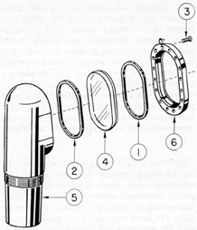
Figure 6-1. Outer head and head window assembly.
Ill. No.
Drawing Number
Num- ber Re- quired
Nomenclature
1
P-1257-8
1
Bezel frame rubber gasket
2
P-1257-9
1
Head window seat rubber gasket
3
P-1260-9
16
Bezel frame lockscrews
4
P-1396-1
1
head window
5
P-1397-1
1
Outer head
6
P-1397-2
1
Bezel frame
a. Outer head. The outer head (5) is made
of solid forged corrosion resisting steel material.
It serves as a covering for the skeleton head
assembly and is assembled to the upper part of
the outer taper section (1, Figure 6-2).
The lower part of the outer head has a tapered
alignment support section with a straight
threaded periphery of 32 threads per inch
preceding it which fits into a similar internal
tapered alignment support and threaded section
in the upper part of the outer tapered section.
A mixture of litharge and glycerin is used over
the threads to maintain an internal gas and
external water seal, thus establishing a permanent joint between the outer head and outer
taper section.
The outer head is bored to accommodate a
sliding fit for the assembly of the skeleton head
frame (1, Figure 6-4) and has additional concave
radius provisions in the upper wall to furnish
sufficient clearance for the operation of the prism
tilt mechanism of the skeleton head assembly
(Figure 6-4).
The outer head flange is machined at an angle
of 8 degrees, with a recess seat to carry a sealing rubber
gasket (2) under a head window (4). Above the
head window, an additional sealing rubber
gasket (1) adheres directly to the beveled edge
of the head window and the beveled seat in the
head window bevel frame (6).
The normal diameter of the outer head is
1.990 inches and tapers outward on opposite
sides to its outer flange face which has a larger
diameter. The exterior surface of the outer
head upper wall tapers inward with the contour
of its flange face surface at an angle of 9 1/2 degrees.
The outer head flange has 16 proportionately
spaced tapped holes for retaining the head
window bezel frame (6) by means of 16 lockscrews (3) which are inserted in countersunk
clearance holes in the head window bezel frame.
b. Head window bezel frame. The head
window bezel frame (6) is made of phosphor
bronze. Its lower face has a machined irregular
recess to fit over the head window (4) with a
45 degrees angle. The 45 degrees angle of the beveled recess
accommodates the head window bezel frame
rubber gasket (1) which compresses to the
angle of the head window (4) to form an airtight joint.
The outer flange of the bezel frame has 16
proportionately spaced countersunk clearance
holes to accommodate the lockscrews (3). These
lockscrews extend into the tapped holes in the
outer head flange (5). The upper side face of the
bezel frame is beveled at a 22 degrees angle conforming
to its contour, while the lower side face is
beveled at a 16 degrees angle also conforming to its
contour.
The inner irregular circumference of the bezel
frame is beveled at an angle 45 degrees away from the
line of contact with the glass to increase the
effect of wind in clearing drops of water from
the glass and to reduce the lodgement of water
286
and deposits of salt by evaporation on the glass
near the inner circumference.
c. Head window. The head window (4)
is made of one crown optical glass element with
parallel surfaces, and fits into the recess seat
in the outer head on a seat gasket (2). It is
molded with a 45 degrees angle edge to which a bezel
frame rubber gasket (1) is applied. It provides
a means of sealing without obstructing the
entering light rays, and offers a transparent
medium through which light is transmitted.
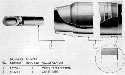
d. Outer taper section. The outer taper
section (1, Figure 6-2) is made of solid forged
corrosion-resisting steel. The external diameter
at the lowest part is machined for connection
to the outer tube (2) in similar manner to the
Type II periscope outer taper section. Refer
to Section 4D1.
The exterior surface of this taper section
starting from the lower undercut part is a
straight shoulder for 1/2 inch. From this straight
shoulder, it is machined with a radius for a
short distance to a diameter of 6 7/8 inches. It
tapers upward to a diameter of 1.990 inches in
47 1/4 inches, which it retains for a distance of
15 inches. The inside diameter upward from the
lower part does not vary from its calculated
diameter at any point by +0.015 inch or
-0.000 inch, and the bore of taper is concentric within 0.005 inch.
The inside diameter of the straight 15 inches
is bored for light transmission, leaving a wall
of approximately 21/64 inch. The upper part is
provided with two counterbored sections. The
small counterbored section is tapered to receive
the tapered alignment section of the outer head
(5), while the large counterbored section is
threaded to receive the threaded periphery of
the outer head as a permanent joint.
e. Outer tube. The outer tube (2, Figure
6-2) is identical to the Type II periscope. Refer
to Section 4D2.
6C2. Disassembly of the head window assembly.
The head window assembly is disassembled in
the following manner:
1. Unscrew each of the 16 lockscrews (3)
evenly, with several threads of each lockscrew
remaining in the tapped holes in the outer head
flange face (5).
Figure 6-2. Outer taper section and outer tube.
287
2. In order to break the seal of the head
window (4), it is necessary to apply an internal
nitrogen pressure of 15 to 30 pounds in the
instrument. To apply an internal nitrogen
pressure requires the blanking off of the lower
part of the outer tube (2, Figure 6-2) with a
suitable jig and fittings for a pressure gage and
the nitrogen line.
3. After the head window (4) is broken free,
release the internal gas pressure and remove
the jig.
4. Remove the 16 lockscrews (3), unscrewing
them from the tapped holes in the flange face
of the outer head (5).
5. Remove the head window bezel frame (6),
lifting it away from the flange face of the outer
head (5).
6. Remove the head window (4) and the head
window bezel frame rubber gasket (1). The head
window may stick to the head window bezel
frame rubber gasket (1) and the bezel frame (6).
Remove the head window bezel frame rubber
gasket (1) and destroy it.
7. Remove the head window seat rubber
gasket (2) from the recess seat in the outer
head (5) and destroy it.
6C3. Cleaning of the outer head, outer taper section
and outer tube. The outer head, outer taper section, and outer tube are cleaned in the following
manner:
1. These parts should be cleaned after flooding
with they use of various sized circular wire
brushes and turkish toweling to remove salt
deposits, and then blown out with filtered air.
2. Under normal conditions turkish toweling
should be used to clean out the outer head,
outer taper section, and outer tube.
3. Place a canvas boot over both the outer
head and the lower end of the outer tube to
prevent any foreign matter from entering the
cleaned outer head, outer taper section, and
outer tube.
6C4. Reassembly of the head window assembly.
The head window assembly is reassembled in
the following manner:
1. Scrape the seat in the outer head (5)
if necessary, to give the head window a true
bearing surface. The head window (4) must be
marked in the position its seat is scraped, so
that it cannot be turned end for end.
2. Insert the new head window seat rubber
gasket (2) into the head window seat of the
outer head (5).
3. The beveled seat of the head window
bezel frame (6) should be scraped if necessary,
to provide a true bearing surface in conjunction
with the beveled edge of the head window (4).
4. Clean the inner surface of the head
window (4) with clean lens tissue, and use a
small air bulb to blow off any surface dust.
5. Place the head window (4) in the recess
seat in the outer head (5) on the head window
seat rubber gasket (2).
6. The head window bezel frame rubber
gasket (1) should be approximately 0.031 inch
larger than the head window outer irregular
circumference, complying with factory drawing
dimensions as to thickness. It is placed in the
head window bezel frame (6) in one solid
piece. A small hole is punched in the center
of the rubber gasket to allow trapped air to
escape.
7. Place the head window bezel frame (6)
with the head window bezel frame rubber gasket
(1) over the head window (4). Insert four lock
screws (3) in four equally spaced positions in
the countersunk clearance holes in the bezel
frame, screwing them in tapped holes in the
flange of the outer head. Each lockscrew is
screwed down loosely, flush with the head
window bezel frame.
8. A flat wooden block 1 inch thick and
slightly smaller than the inner circumference
of the head window bezel frame (6) is placed
over the head window bezel frame rubber gasket
(1). A C-clamp is placed over the wooden block
and the outer head (5) to flatten the raised
center portion of the rubber gasket. Use a
wooden wedge on the opposite side of the outer
head to tighten the C-clamp evenly. The
flattening of the rubber gasket forces its outer
edges to adhere to the inner beveled walls of
the head window bezel frame (6), and utilizes
the entire area of the beveled surface of the head
window bezel frame to maintain the seal.
288
9. Lubricate the threads of the 16 lockscrews
(3) Tightly with a medium grease before insertion
in the bezel frame, and tighten them evenly.
Each lockscrew is taken down equally in a
series of all-around adjustments and a feeler
gage is used as a check around the head window
bezel frame (6), to determine the equal tension.
Remove the C-clamp and wooden block.
10. It is desirable to wet the head window
bezel frame rubber gasket (1) thereby offering
a lubricant for a brass knife edge when cutting
the crude rubber gasket around the inner
irregular circumference of the head window
bezel frame (6). The brass blade will not scratch
the head window surface.
11. Clean the outer surface of the head window
(4) in the same manner as outlined in Step 4
of this section.
6C5. Inner tube assemblies.Figure 6-3 at the
back of the book shows the inner tube of the
periscope which is divided into three telescope
systems. Each telescope system is made up of
assemblies as follows:
A. Galilean telescope system: Skeleton head
assembly.
B. Upper main telescope system.
1. Part I. First, second, third, fourth, and
fifth reduced tube sections, and fifth
and sixth inner tube sections
2. Part II. Second, third, and fourth
inner tube sections.
C. Lower main telescope system.
1. Lower (split) objective lens and mount
assembly.
2. Objective operating mechanism assembly.
3. First inner tube section assembly.
4. Eyepiece skeleton assembly.
5. Eyepiece box and miscellaneous assemblies.
a.
One stadimeter transmission shaft packing gland assembly and four spring loaded packing gland assemblies.
b.
Eyepiece window assembly.
6. External projections to the eyepiece
box.
a.
Stadimeter housing assembly.
b.
Focusing knob assembly.
c.
Rayfilter assembly.
d.
Eye buffer and blinder assembly.
e.
Variable density polaroid filter assembly.
f.
Training handle assemblies.
g.
Stadimeter illuminator assembly.
h.
Hoisting yoke assembly.
D. SEPARATION OF THE THREE TELESCOPE SYSTEMS
6D1. Disassembly of the-shifting wire tapes and air
line sections. This procedure is performed in the
following manner:
1. Remove the 10 lockscrews each (5, Figure
4-29) from the left side plate (9) and the pressure
gage assembly (21). Unscrew the 10 lockscrews
each from the tapped holes in the rectangular
recess seats in the left and right sides of the
eyepiece box (11). Its may be necessary to tap
out two opposite holes located diagonally with
an 8-32 tap in the side plate (9) and pressure
gage assembly (21) for the insertion of special
lockscrews to break the seal of the two rubber
gaskets (10). Remove the side plate and pressure
gage rubber gaskets and destroy them.
2. Remove the shifting wire tape (38,
Figure 4-28) from the clamp blocks (11, Figure
6-4), removing and replacing the lockscrews
(49) and clamp blocks (11) to the prism and
cube shifting racks (14, 15, 12, and 13) of the
skeleton head assembly.
3. Remove each of the four lower shifting
wire spindle adjusting nuts (4, Figure 4-28)
one by one from each shifting wire spindle
assembly, by following the method used under
Step 5 of Section 4C1. Carry each of the prism
and power shifting racks (43, 44, 45, and 46)
to its lower position after removing each shifting
wire spindle adjusting nut (4) for the removal of
the shifting wire spindle assemblies and each
289
shifting wire tape one by one, carrying each
out through the rectangular openings of its
respective sides of the eyepiece box (11, Figure
4-29). Roll each shifting wire tape into a 15-inch
diameter roll and secure each coil together with
three pieces of friction tape.
4. Remove the two lockscrews (27, Figure
6-5) and the removable air line strap (26)
from the first reduced tube section (23). Pull
the air line section continuation (25) away
from the periphery wall of the first reduced tube
section (23) to remove the air line section (22)
of the second reduced tube section (17) from the
air line adapter (20) of the same reduced tube
section.
5. Slide the air line section (22) of the second
reduced tube section (17) upward, carrying
its continuation (25) of the first reduced tube
section (23), and its continuation (35) of the
sixth inner tube section (28), with its soldered
air line coupling (36) from its connection with
the upper part of the air line section (37) of
the sixth inner tube section. Slide it downward
from the three soldered air line straps (39)
of the sixth inner tube section, and one soldered
air line strap (21) of the second reduced tube
section (17).
6. Remove the two lockscrews (40) and the
removable air line strap (38) from the lower
part of the sixth inner tube section (28). Slide
the air line section (37) of the sixth inner tube
section upward, carrying its continuation (47)
of the fifth inner tube section (41), its continuation
(9, Figure 6-6) of the fourth inner tube
section (1), and its continuation (21) of the
third inner tube section (11) upward. It is
carried upward sufficiently to disconnect its
soldered air line coupling (20) from the air line
section (19) of the third inner tube section (11).
Carry the air line section continuation (21)
with its soldered airline coupling (20) downward
for removal. Slide it out of two soldered air
line straps (22) of the third inner tube section
(11) and its air line section continuations (9, 47,
Figure 6-5), of the air line section (37) from the
seven soldered air line straps (10, Figure 6-6)
of the fourth inner tube section (1).
7. Remove the two lockscrews (33) and the
removable air line strap (31) from the second
inner tube section (23). Remove the two lockscrews
(22, Figure 6-10), and the air line strap
(18) from the upper part of the first inner
tube section (1). Slide the air line section
continuation (17) of the first inner tube section
(1) and its soldered air line coupling (15) upward
to disconnect the coupling from the air line
section (16) of the first inner tube section (1).
Carry the air line section continuation (17)
with its soldered air line coupling (15) downward
for removal. Slide its continuations (30 and 19,
Figure 6-6) from six soldered air line straps
(32) of the second inner tube section (23) and
four soldered air line straps (22) of the third
inner tube section (11).
8. Remove two lockscrews (22, Figure 6-10)
and the removable air line strap (20) from the
lower part of the first inner tube section (1).
Slide the air line section (16) upward, carrying
with it at its lower end the soldered air line
coupling (15), disconnecting it from the short
bent round air line (14). Slide the air line
section (16) and its coupling (15) upward,
bending it slightly outward and carrying it out
of the soldered air line strap (19) of the first
inner tube section (1).
9. Remove the short bent round air line
(14), disconnecting it from the undercut section
of the long round air line coupling section (13).
10. Unscrew the long round air line coupling
section (13) from the tapped hole in the large
shoulder flange of the eyepiece skeleton (42,
Figure 4-28), sliding it out of the clearance hole
in the bearing projection of the spider (2,
Figure 6-10).
6D2. Separation of the Galilean telescope system.
This procedure is performed in the following
manner:
1. Remove the two lockscrews (55, Figure
6-4), unscrewing them from the tapped holes
in opposite sides of the upper threaded periphery
alignment support section of the fifth inner tube
section (1, Figure 6-5), carrying them out of
opposite countersunk clearance holes in the
skeleton head (1, Figure 6-4).
2. Remove the skeleton head assembly, unscrewing it from the upper threaded periphery
alignment support section of the fifth reduced
tube section (1, Figure 6-5). Wrap the skeleton
290
head in clean lens tissue and place it to one side
to prevent its becoming damaged.
6D3. Separation of the upper telescope system
Part I from Part II and Part II from the lower telescope
system. This procedure is performed in the
following manner:
1. Remove the eight lockscrews (42, Figure
6-5), from the lower part of the fifth inner
tube section (41). Unscrew these lockscrews
from tapped holes in the upper alignment
support section of the fourth inner tube section
upper end coupling (4, Figure 6-6).
2. Unscrew the lower part of the fifth inner
tube section (41, Figure 6-5) from the threaded
periphery of the fourth inner tube section upper
end coupling (4, Figure 6-6). Support the
reduced tube sections while unscrewing the
lower part of the fifth inner tube section.
3. Remove the 15 lockscrews (11, Figure 6-7)
from the lower part of the coupling sleeve (17).
Unscrew these lockscrews from the tapped holes
in the large flange section of the track sleeve
(18).
4. Slide the lower telescope system approximately 1 foot clear of the coupling sleeve (17).
5. Remove the four lockscrews (8) from the
upper part of coupling sleeve (17). Unscrew
these lockscrews from tapped holes in the lower
alignment support section of the second inner
tube section lower end coupling (26, Figure 6-6).
6. Unscrew the coupling sleeve (17, Figure
6-7) from the lower part of the second inner
tube section lower end coupling threaded
periphery (26, Figure 6-6).
6D4. Separation of the lower telescope system.
This procedure is performed in the following
manner:
1. Remove the two stadimeter collimating
screws (13, Figure 4-22) from each half of the
lower (split) objective lens and mount assembly.
These lockscrews are unscrewed from tapped
holes in each mounting plate half (1, Figure
6-7) of the objective operating mechanism
assembly. The straight dowel pins (15, Figure
4-22) will be carried out with the mounts (1
and 2) from the mounting plates (1, Figure 6-7).
2. Remove the taper pin (15) from the upper
part of the stadimeter transmission shaft coupling (3).
3. Remove the two taper pins (10) from the
two stadimeter transmission shaft thrust collars
(4, Figure 6-10) located on the stadimeter
transmission shaft (12) on each side of the spider
(2) of the first inner tube section assembly.
4. Remove the taper pin (15, Figure 6-7)
from the lower part of the stadimeter transmission shaft coupling (3).
5. Slide the stadimeter transmission shaft
(12, Figure 6-10) out of the stadimeter transmission shaft coupling (3, Figure 6-7) and clear
of the track sleeve (18). Remove this coupling
from the operating gear pinion shaft (20).
6. Remove the four lockscrews (9) from the
lower part of the track sleeve (18). Unscrew
these lockscrews from the tapped holes in the
upper alignment support section of the first
inner tube section upper end coupling (23,
Figure 6-10).
7. Unscrew the track sleeve (18, Figure
6-7) from the upper part of the first inner tube
section upper end coupling threaded periphery
(23, Figure 6-10), and remove the objective
operating mechanism assembly.
8. Remove the stadimeter transmission shaft
(12) from the first inner tube section assembly,
also removing the two thrust collars (4) from
each side of the spider bearing projection (2).
9. Check the reference marks on all four
spring loaded packing gland assemblies with
corresponding reference marks on the eyepiece
box (11, Figure 4-29).
10. Follow the procedure described under
Steps 10 to, 22 inclusive of Section 4E5, for
the removal of the four spring loaded packing
gland assemblies (Figures 4-32, 4-33, and 4-34
respectively), stadimeter transmission shaft
spring type packing gland (Figure 4-30), modified hycar type, (Figure 4-31), rayfilter plate (2,
Figure 4-40), eyepiece window frame assembly.
(Figure 4-38), eyepiece box (11, Figure 4-29),
and the eyepiece skeleton assembly (Figure
4-28). All of these assemblies are identical to
the Type II periscope.
291
E. GALILEAN TELESCOPE SYSTEM
6E1. Description of the skeleton head assembly.
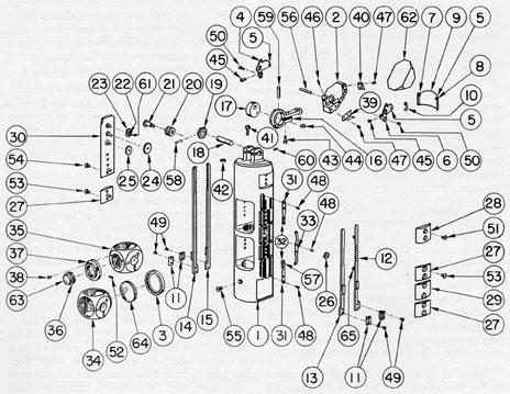
Figure 6-4 shows the skeleton head assembly.
All bubble numbers of Sections 6E1, 2, and 3,
refer to Figure 6-4 unless otherwise specified.
Ill. No.
Drawing Number
Num- ber Re- quired
Nomenclature
1
P-1254-1
1
Skeleton head
2
P-1255-1
1
Head prism mount
3
P-1255-2
1
Galilean objective lens retainer
4
P-1255-3
1
Head prism side plate (left)
5
P-1255-3A
4
Head prism shade and side plate wire link rivets
6
P-1255-4
1
Head prism side plate (right)
7
P-1255-5
1
Head prism shade arm (left)
8
P-1255-6
1
I Head prism shade arm (right)
9
P-1255-7
1
Head prism shade
10
P-1255-8
2
Head prism shade wire links
11
P-1255-9
4
Clamp blocks
12
P-1255-10
1
Cube shifting rack (right)
13
P-1255-11
1
Cube shifting rack (left)
14
P-1255-12
1
Head prism shifting rack (right)
15
P-1255-13
1
Head prism shifting rack (left)
16
P-1256-1
1
Eccentric arm
17
P-1256-2
1
Eccentric disk
18
P-1256-3
1
Eccentric disk shaft
19
P-1256-4
1
Head prism shift actuating gear
20
P-1256-5
1
Fourth intermediate head prism shift gear
21
P-1256-6
1
Fourth intermediate head prism shift-gear shaft
22
P-1256-7
1
Third intermediate head prism shift gear
23
P-1256-8
1
Second intermediate head prism shift gear
24
P-1256-9
1
First intermediate head prism shift gear
25
P-1256-10
1
Head prism shift gear
26
P-1256-11
1
Power shift gear
27
P-1256-12
3
Cube brackets
28
P-1256-13
1
Head prism base bracket (right)
29
P-1256-14
1
Power shift gear bracket
30
P-1256-15
1
Gear train bracket
31
P-1256-16
2
Pawl holders
32
P-1256-17
2
Power shift pawls
33
P-1257-1
1
Reinforcing spring
34
P-1257-2
1
Galilean objective lens cube
35
P-1257-3
1
Galilean eyepiece lens cube
36
P-1257-4
1
Galilean eyepiece lens mount
Ill. No.
Drawing Number
Num- ber Re- quired
Nomenclature
37
P-1257-5
1
Galilean eyepiece lens mount housing
38
P-1257-6
3
Galilean eyepiece lens mount housing lockscrews
39
P-1257-11
2
Right prism mounting clamps
40
P-1257-12
2
Left prism mounting clamps
41
P-1260-1
2
Split bearing lockscrews
42
P-1260-1A
2
Split bearing lockscrew spacer washers
43
P-1260-2
2
Eccentric arm lockscrews
44
P-1260-2A
2
Eccentric arm lockscrew spacer washers
45
P-1260-3
2
Head prism side plate bottom lockscrews
46
P-1260-4
1
Eccentric arm pivot pin lockscrew
47
P-1260-5
8
Head prism mounting clamp lockscrews
48
P-1260-6
6
Detent pawl holder and reinforcing spring lockscrews
49
P-1260-7
8
Clamp block lockscrews
50
P-1260-8
2
Head prism side plate lockscrews
51
P-1260-10
2
Head prism base bracket lockscrews
52
P-1260-12
1
Galilean eyepiece lens mount lockscrew
53
P-1260-13
8
Cube bracket lockscrews
54
P-1260-14
4
Gear train bracket lockscrews
55
P-1260-15
2
Skeleton head and fifth reduced tube section lockscrews
Second and third intermediate prism shift gear rivets
62
P-1396-2
1
Head prism
63
P-1396-3
1
Galilean eyepiece lens
64
P-1396-4
1
Galilean objective lens
65
2
Right cube shifting rack pins
a. Skeleton head frame. The skeleton
head frame (1) is made of cast phosphor-bronze
material. It forms the necessary framework to
292
carry the prism tilt mechanism, Galilean
telescope, and change of power mechanism. It
is bored for light transmission, with antireflection threads in its central part, and is
provided with three counterbored sections.
The second largest counterbored section serves
as an alignment support section for the upper
alignment support section of the fifth reduced
tube section (1, Figure 6-5), while the largest
counterbored threaded section engages on the
threaded periphery of the upper part of the fifth
reduced tube section (1, Figure 6-5). It is secured
to the fifth reduced tube section with two lockscrews (55).
The skeleton head frame is a sliding fit in
the inside bore of the straight 1.99-inch section
of the outer taper section.
The prism tilt mechanism is composed of
numerous mechanical parts in the upper and
left side wall of the skeleton head to operate
one optical element, the head prism (62).
b. Head prism, head prism mount, head
prism side plates, and head prism shade.
1. Head prism. The head prism (62) is a right
angle prism, made of dense flint optical glass
material. It is used to reflect the light rays at
right angles. The light rays enter from any
position of elevation between 61 degrees elevation to
26 degrees depression in low power and from 49 degrees
elevation to 14 degrees depression in high power, and
are deflected downward into the instrument from
any of the above angles.
2. Head prism mount. The head prism
mount (2) carries the head prism (62) with a
suitable clamping arrangement. The base pivot
shoulder projections of the mount project
outward on opposite sides and are a sliding fit
in the milled out clearance section in the upper
Figure 6-4. Skeleton head assembly.
293
part of the skeleton head frame (1). Each
shoulder is provided with a reamed hole axis
to receive the integral pin projections of the
gear train bracket (30) and the right head
prism base bracket (28). Each bracket pin
projection extends into reamed holes in its
respective side walls of the skeleton head
frame (1) into the reamed hole axis in each base
pivot shoulder.
The rear face of the mount is provided with
two bearing projections for the insertion of the
extended arm bearing section of the eccentric
arm (16) attached to the mount with an eccentric
arm pivot pin (56) and secured with a headless
lockscrew (46). The skeleton head frame is
provided with clearance in its milled out section
to receive the eccentric arm (16) and the head
prism mount (2) for all degrees of elevation
and depression. The head prism (62) is retained
from sideward movement with two head prism
side plates left and right (4 and 6), and is held
to the head prism mount (2) with two pairs of
head prism mounting clamps (39 and 40) which
are secured with two lockscrews each (47).
3. Head prism side plates. The left and
right head prism side plates (4 and 6) are
attached to the head prism mount (2) with two
lockscrews each (45 and 50). These side plates
retain the head prism (62) from sideward
movement. Attached to each side plate are
two head prism shade wire links (10) secured
with rivets (5). The opposite ends of each wire
link are secured to each rivet (5) of the head
prism shade arms left and right (7 and 8) which
are soldered to the head prism shade (9).
Each side plate has a clearance hole to slide
over the base pivot shoulder projection of the
head prism mount (2) and a bent-over section
for its securement to the lower face of the mount
with one lockscrew each (45).
4. Head prism shade. The head prism
shade (9) is made of sheet brass and is constructed to conform to the contour of the skeleton
head periphery. The sides are bent downward
and again at 90 degrees to fit into a vertical slot in each
of the inner side walls of the skeleton head.
Two arms left and right (7 and 8) are attached
to the downward bent sides of the shade by
soldering. Each arm is bent and has a protruding
section to which the lower ends of the wire links
(10) are secured with rivets (5). As the head
prism (62) and its mount (2) are elevated or
depressed, the head prism shade is carried
vertically and is used principally in the elevated
position to shade the lower 90 degrees face of the head
prism, thus preventing a double image.
c. Eccentric arm. The eccentric arm (16)
is made of phosphor bronze and is 1 7/8 inches
in length. The large section has a reamed hole
with a stub arm section separated from the
long arm section with a sawed slot, and fits
over the eccentric disk (17). The stub section is
provided with two spacer washers (44) fitted
in the slotted section.
The stub arm is provided with two countersunk clearance holes, while the long section
of the eccentric arm is provided with coinciding
tapped holes for the two lockscrews (43).
These lockscrews are inserted in countersunk
clearance holes in the stub arm section of the
eccentric arm (16) into the clearance holes in
the two spacer washers (44) and screwed into
tapped holes in the long section of the eccentric
arm. The two spacer washers (44) allow sufficient
sliding clearance over the eccentric disk (17).
The eccentric arm (16) assembled to the
eccentric disk (17) actuates the head prism
(62) and its mount (2) by means of the extended
arm bearing section assembled over the eccentric arm pivot pin (56) between the two bearing
projections of the head prism mount base (2)
for elevation and depression.
Two opposite clearance holes are provided
in the large section of the eccentric arm for
the insertion and removal of the eccentric disk
and shaft taper pin (59).
The eccentric warm operates over the eccentric
disk (17) and the eccentric disk shaft (18)
between the two split bearing projections in
the upper part of the skeleton head frame (1).
d. Eccentric disk and shaft.1. Eccentric
disk. The eccentric disk (17) is made of corrosion resisting steel material 1/4 inch in width
and 5/8 inch in diameter. It is provided with
a reamed hole with its centerline offset from
its axis 1/8 inch to accommodate an eccentric
disk shaft (18). The eccentric disk is provided
with a reamed taper pin hole perpendicular
294
to the offset eccentric disk shaft reamed hole,
to secure the eccentric disk to the shaft.
The offset reamed hole provides the necessary
cam movement for the actuation of the head
prism mount (2) and its head prism (62) to all the
required degrees of elevation and depression.
2. Eccentric disk shaft. The eccentric disk
shaft (18) is made of corrosion-resisting steel
and is 27/32 inch in length. It is a sliding fit
into the reamed holes in the two split bearing
projections of the upper part of the skeleton
head frame (1) and the offset reamed hole in
the eccentric disk (17).
The shaft is secured in the split bearing
projections by the tightening of the two lockscrews (41). The two spacer washers (42) fit
into the slotted section in each split bearing
projection to provide sufficient rotation of the
shaft by securing the lockscrews (41). The axial
displacement of the shaft is maintained by the
eccentric disk (17) and its allowed clearance
between the two split bearing projections.
The protruding part of the shaft on the left
side carries the head prism shift actuating gear
(19) which is secured with a taper pin (58).
e. Head prism shift actuating-gear. The
head prism shift actuating gear (19) is made
of phosphor bronze material. It has 30 teeth of
60 diametral pitch around its outer circumference, to mesh with the teeth of the fourth
intermediate prism shift gear (20).
The reamed hole in the axis of this gear is a
push fit on the protruding part of the eccentric
disk shaft (18) and is secured with a taper pin
(58) through the hub section.
f. Fourth intermediate head prism shift
gear and shaft. 1. Fourth intermediate
head prism shift gear. The fourth intermediate
head prism shift gear (20) is made of phosphor
bronze and is 21/64 inch in length. It has 23
teeth of 60 diametral pitch around its outer
circumference to mesh with teeth of the third
intermediate head prism shift gear (22) on one
side, while it meshes with the head prism shift
actuating gear (19) on the opposite side. It
has two undercut shoulders on opposite ends
of 1/64-inch width.
It has a reamed hole in its axis to receive the
shaft (21). The gear is mounted with the fourth
intermediate head prism shift gear shaft (21)
in the left side of the skeleton head frame in a
semicircular clearance provision.
2. Fourth intermediate head prism shift
gear shaft. The fourth intermediate head
prism shift gear shaft (21) is made of corrosion-resisting steel and is 0.578 inch in length. It
is provided with three shoulder sections. The
stem section fits into the reamed hole in the
skeleton head frame (1) and is secured with a
lockscrew (60) located in the front of the
skeleton head frame. The medium shoulder
is a sliding fit in the reamed hole axis in the
fourth intermediate head prism shift gear
(20), while the large narrow shoulder serves to
retain the above gear axially. The large narrow
shoulder has a concave relief to allow clearance
for the actuation of the second intermediate
head prism shift gear (23).
g. Third intermediate head prism shift
gear. The third intermediate head prism shift
gear (22) is made of corrosion-resisting steel
and is 0.063 inch in width. It is provided with
an undercut shoulder of 0.008-inch width for
its metal to metal contact upon assembly to
the second intermediate prism shift gear (23).
It has 14 teeth of 60 diametral pitch around its
outer circumference, to mesh with the teeth
of the fourth intermediate head prism shift gear
(20) as it is fitted into the small countersunk
recess in the upper part of the skeleton head
left side wall.
This intermediate gear has a reamed hole in
its axis which is a sliding fit over the first upper
pin projection of the gear train bracket (30).
It is provided with two opposite No. 72 drilled
holes for the insertion of rivets (61) and is
secured to the second intermediate head prism
shift gear (23) and riveted.
h. Second intermediate head prism shift
gear. The second intermediate head prism
shift gear (23) is made of corrosion-resisting
steel and is 0.075 inch in width. It is provided
with an undercut shoulder of 0.013-inch width.
It has 18 teeth of 48 diametral pitch around its
outer circumference to mesh with the teeth
of the first intermediate head prism shift gear
(24) as it is fitted in the countersunk recess in
295
the upper part of the skeleton head left side
wall.
This intermediate gear has a reamed hole in
its axis which is a sliding fit over the first upper
pin projection of the gear train bracket (30),
with the undercut shoulder fitting in the countersunk recess in the gear train bracket. It is
provided with two opposite No. 72 drilled holes
for the insertion of rivets (61) and is secured to
the third intermediate head prism shift gear
(22) and riveted.
i. First intermediate head prism shift
gear. The first intermediate head prism shift
gear (24) is made of phosphor bronze. It is
identical in all other respects to the second
intermediate head prism shift gear (23) except
that it has no opposite drilled holes for rivets.
This intermediate gear has a reamed hole in
its axis which is a sliding fit over the second
upper pin projection of the gear train bracket
(30), with the undercut shoulder fitting in the
countersunk recess in the gear train bracket.
It engages with the teeth of the second intermediate head prism shift gear (23) as it is fitted
in the countersunk recess in the upper part of
the skeleton head left side wall, and with the
teeth of the head prism shift gear (25) on its
lower opposite side.
j. Head prism shift, gear and shifting
racks. 1. Head prism shift gear. The head
prism shift gear (25) is made of corrosion-resisting steel and is 0.075 inch in width. It is provided
with an undercut shoulder of 0.013-inch width.
It has 23 teeth of 48 diametral, pitch around
its outer circumference to mesh with the teeth
of the head prism shifting racks right and left
(14 and 15), and the first intermediate head
prism shift gear (24) as it is fitted in the countersunk recess in the upper part of the skeleton head
left side wall.
It is provided with a reamed hole in its axis
which is a sliding fit over the second lower pin
projection of the gear train bracket (30) with
the undercut shoulder fitting in the countersunk
recess of the gear train bracket.
2. Head prism shifting racks. The right
and left head prism shifting racks (14 and 15)
are made of blued cold rolled steel, and operate
in vertical slots in the skeleton head left side
wall. The left shifting rack (15) is made of
nominal width and thickness and is provided
with 20 gear teeth of 48 diametral pitch in the
upper part of its right side in a distance of
1.250 inch, to mesh with teeth of the head
prism shift gear (25) on the left side. This
shifting rack (15) is offset to the right in the
lower part for attachment of the shifting wire
tape (38, Figure 4-28), secured with a clamp
block (11) and two lockscrews (49). The lower
section of the skeleton head is provided with a
flat recess to allow clearance for operation of the
prism shifting racks. Two tapped holes are
provided in the centerline of the lower offset
section of the shifting rack for two lockscrews
(49).
The shifting wire tape (38, Figure 4-28),
overlaps the narrow flat shoulder in the lower
part of the skeleton head and is attached to
the shifting rack (15) which is slightly higher.
The clamp block (11) is made of the same material as the shifting rack and coincides with the
length and width of the offset and main section.
The periphery of the clamp block conforms to
the contour of the skeleton head, as it operates
vertically with the shifting rack slightly below
the skeleton head periphery.
Above the offset section of the shifting rack,
a protruding integral stop section 11/32 inch
in length is located approximately 21/32 inch
from the lower end. Its outer surface is provided
with a radius slightly below the contour of
the skeleton head periphery. The stop section
in contact with the lower side of the cube
bracket (27) restricts the movement of the head
prism (62) in the elevated position to its designed limits, thus preventing any damage to
the head prism (62) and its operating mechanism.
The right head prism shifting rack (14) is
similar to the left in design, except that it is
constructed to the opposite hand. Its teeth
mesh with the teeth of the head prism shift
gear (25) on the right side. The integral stop
section of this shifting rack when in contact
with the lower side of the cube bracket (27)
restricts the movement of the head prism (62)
in the depressed position to its designed limit.
k. Gear train bracket. The gear train
bracket (30) is made of blued cold rolled steel,
296
and serves various functions. It serves to carry
the gear train of the first, second, and third
intermediate head prism shift gears (24, 23,
and 22), and the head prism shift gear (25), by
means of three pin projections integral with
the bracket. It provides a closed housing by
means of countersunk recesses below each of
the three upper pin projections for the first
and second intermediate and the head prism
shift gear (24, 23, and 25), and also serves as a
retaining plate for the upper part of the head
prism shifting racks right and left (14 and 15).
The lower integral pin projection serves as a
pivot for the reamed axis hole in the Galilean
eyepiece lens cube (35). The second upper pin
projection is of sufficient length to protrude
into the reamed axis hole in the head prism
mount (2) base pivot shoulder projection serving
as a pivot for the left side of the mount. All
four pin projections are a sliding fit into the
reamed holes in the left side wall of the skeleton
head. The bracket is secured in the flat recess
face of the skeleton head left side wall with four
lockscrews (54) located in the lower part.
The periphery of the bracket when assembled
to the skeleton head conforms to the skeleton
head periphery.
l. Cube bracket. The cube bracket (27) is
made of blued cold rolled steel. It serves to
retain the lower part of the head prism shifting
racks right and left (14 and 15). The pin projection integral with the cube bracket serves as a
pivot for the reamed hole axis of the Galilean
objective lens cube (34).
The pin projection is a sliding fit into the
reamed hole in the skeleton head vertical
centerline of the left side wall. The bracket is
secured to the flat recess face of the skeleton
head with two lockscrews (53) which are inserted
in countersunk clearance holes in the bracket on
opposite sides of the pin projection and screwed
into tapped holes in the skeleton head. This
bracket serves as a stop for each integral stop
section of the head prism shifting racks (14 and
15) for the elevation and depression positions
of the head prism (62).
m. Galilean eyepiece lens, lens mount
housing, lens cube, objective lens, and
objective lens cube. The Galilean telescope
system is composed of two lenses; namely, a
negative Galilean eyepiece lens doublet and a
positive Galilean objective lens doublet. It is
used in reverse to effect a low-power magnification and increase the true field of view.
1. Galilean eyepiece lens. The Galilean
eyepiece lens (63) is made of two optical elements. It consists of a divergent meniscus flint
element, cemented to the equi-concave crown
element, forming a negative doublet. The divergent meniscus element cemented to the equi-concave element of the Galilean eyepiece lens
corrects for spherical and chromatic aberration.
It is mounted in the Galilean eyepiece lens mount
(36) and burnished in place. The threaded periphery of the mount can be screwed vertically
in the threads of the Galilean eyepiece lens
mount housing (37) by using a sharp pointed
scribe inserted in any one of a series of eight
drilled recesses. This vertical movement provides a means for focusing the Galilean eyepiece
lens for elimination of parallax in low power.
2. Galilean eyepiece lens mount housing.
The Galilean eyepiece lens mount housing (37)
is provided with an internal threaded bore to
carry the threaded periphery of the mounted
Galilean eyepiece lens (63) and mount (36)
vertically. Two undercut shoulders, one on
each side of the flange section, provide sufficient
body distance for the movement of the mounted
Galilean eyepiece lens (63) and mount (36) to
eliminate parallax. The housing flange has three
equally spaced clearance holes. One hole is a
pivot hole, while the other two are elongated
for collimation. A tapped hole located in the
undercut shoulder receives the lockscrew (52)
used to secure the mounted Galilean eyepiece
lens (63) and mount (36) after parallax removal.
3. Galilean eyepiece lens cube. The Galilean eyepiece lens cube (35) is constructed of a
suitable blued cold rolled steel framework for
holding the Galilean eyepiece lens mount housing
(37). By means of integral pin projections of the
cube bracket (27) and the gear train bracket
(30) extending in the reamed hole axis in
opposite sides of the cube, it can be rotated for
change of power. The undercut shoulder 0.010
inch in width and 0.437 inch in diameter on
each side face provides sufficient bearing wall for
preservation of alignment between the inner
walls of the skeleton head. All corners are
297
rounded off with a radius of 3/4 inch. The two
perpendicular 90 degrees V-grooves in the right side
wall receive the upper pawl (32) which is
attached to the pawl holder (31) with rivets (57).
The pawl is held in either V-groove with a
reinforcing spring (33) to retain the cube in
either the IN or OUT position. The 90 degrees rotation
of the cube is accomplished by the upper pin
projection (65) of the right cube shifting rack
(12) extending into the elongated slot in the
right side face of the cube.
The clearance hole in the upper face of the
cube allows the lower undercut shoulder of the
Galilean eyepiece lens mount housing (37)
sufficient free movement for collimation of the
Galilean eyepiece lens (63). Three equally
spaced tapped holes in the upper face, receive
lockscrews (38) to secure the Galilean eyepiece
lens mount housing (37) after collimation. The
lower wall is bored and provided with antireflection threads. The front and rear walls are
also bored and have antireflection threads, thus
offering no obstruction for the entering light rays
in either high or low power. The skeleton head
is machined out, leaving only the side walls,
center support, and lower section for the
assembly, disassembly, and actuation of this
cube.
4. Galilean, objective lens. The Galilean
objective lens (64) is made of two optical elements. It consists of a double convex flint
element cemented to a divergent meniscus
dense crown element forming a positive objective
lens doublet. It is mounted in the Galilean
objective lens cube (34) and secured with a
Galilean objective lens retainer (3). The retainer
is spot soldered to the Galilean objective lens
cube (34) to prevent it from unscrewing.
5. Galilean objective lens cube. The Galilean objective lens cube (34) is constructed
similarly to the Galilean eyepiece lens cube (35).
The lower part is counterbored a shallow depth
to serve as a mount for the Galilean objective
lens (64), while its outer shoulder is threaded
to receive the internal threaded section of the
Galilean objective lens retainer (3). The upper,
front, and rear walls are bored and provided
with antireflection threads, thus offering no
obstruction for the entering light rays in either
high or low power. The two perpendicular 90 degrees
V-grooves in the right side wall receive the lower
pawl (32) which is attached to the pawl holder
(31) with rivets (57). The pawl is held in either
V-groove with the reinforcing spring (33) to
retain the cube in either the IN or OUT position.
The 90 degrees rotation of the cube is accomplished by
the lower pin projection (65) of the right cube
shifting rack (12), extending into the elongated
slot in the right side face of the cube. The lower
part of the skeleton head is machined out in
similar manner to that of the Galilean eyepiece
lens cube (35), leaving only the side walls to
accommodate sufficient clearance for the assembly, disassembly, and actuation of this cube.
The change of power mechanism is located
on the right side wall of the skeleton head frame
(1) and is composed of numerous parts to
operate the Galilean telescope system.
n. Cube shifting racks. The cube shifting
racks right and left (12 and 13) operate in
vertical slots located in the right side wall
of the skeleton head. These shifting racks are
made of blued cold rolled steel and are constructed similarly to the head prism shifting
racks right and left (14 and 15). The right
cube shifting rack (12) is wider, and is provided with two assembled and riveted pins (65).
These pins extend through two elongated holes
in the wide vertical slot to the right of the
vertical centerline and into the elongated holes
in the Galilean eyepiece lens and objective lens
cubes (35 and 34).
These pin projections (65), by the movement
of the right or left cube shifting racks (12 and
13), shift the Galilean telescope system to the
IN or OUT position. That is, each cube carrying
one lens doublet each of the Galilean telescope
is shifted simultaneously to place the lenses in
the line of sight for low power, or out of the line
of sight to allow the light rays free passage
through the cubes for high power.
The cubes (34 and 35) are retained in either
position by means of two pawls (32) extending
through elongated slots under spring tension in
either 90 degrees V-groove in the right side wall of
each cube. The right and left cube shifting racks
(12 and 13) are provided with 10 teeth of 48
diametral pitch located 2 7/32 inches from the
lower end in a distance of 11/16 inch, to engage
the power shift gear (26) on opposite sides.
298
The left cube shifting rack (13) is narrower than
any of the head prism shifting racks (14 and 15)
and the right cube shifting rack (12).
This left cube shifting rack (13) operates in
the vertical slot to the left of the vertical
centerline. When it is pulled downward by the
shifting wire tape (38, Figure 4-28), its teeth
in mesh with the power shift gear (26) cause it
to rotate. The power shift gear is also in mesh
with the teeth of the right cube shifting rack
(12) and causes it to be carried upward. By
means of the protruding pins (65) extending
through the elongated holes in the skeleton head
and into the elongated holes in each cube, the
power shift gear rotates the cubes to the OUT
position and vice versa.
The integral stops of the cube shifting racks
projecting outward in each vertical recess groove,
contact the lower side face of the lower cube
bracket (27) to restrict the movement of each
cube beyond its 90 degrees V-groove engagement of
both pawls (32).
The lower section of the skeleton head is
provided with a flat shallow groove in the right
side in similar manner to the left side. The lower
part of each cube shifting rack is offset in similar
manner to the head prism shifting racks (14 and
15) for the attachment of the shifting wire tape
(38, Figure 4-28), clamp blocks (11) and lockscrews (49).
o. Power shift gear and pawls.1. Power
shift gear. The power shift gear (26) is made
of corrosion-resisting steel, and is provided with
two undercut shoulder sections 0.005 inch wide
on opposite sides. It has 12 teeth of 48 diametral
pitch around sits outer circumference. The gear
sets in a countersunk recess in the vertical
centerline and central part in the right side wall
of the skeleton head (1). Its gear teeth are in
mesh with the teeth of both cube shifting racks
right and left (12 and 13) on opposite sides. A
reamed hole in the renter axis of the gear is a
sliding fit over the pin projection of the power
shift gear bracket (29), with its outer shoulder
fitting in the countersunk recess in this bracket.
This gear serves to provide movement to the
opposite cube shifting rack, carrying it upward
as one cube shifting rack is carried downward
and vice versa.
2. Power shift pawls. The two power shift
pawls (32) are made of tool steel with an over-all
length of 3/8 inch. The detent section is constructed at a 90 degrees angle, to engage in either of the
90 degrees V-grooves in each Galilean objective lens
and eyepiece lens cubes (34 and 35) through the
elongated holes in the outer left vertical slot
in the right side wall of the skeleton head.
Each pawl is attached to a pawl holder (31)
made of sheet bronze and having two rivets
(57). The left vertical slot of the skeleton head
frame has three enlarged recess sections to
accommodate the wider sections of the pawl
holders (31) and the reinforcing spring (33).
The pawl holders and the reinforcing spring
are secured with two lockscrews each (48).
The reinforcing spring (33) is made of clock
spring material, bent to shape, with a wide
center section for the insertion of two lockscrews (48). The upper and lower narrow sections of the reinforcing spring (33) overlapping
the ends of the power shift pawls (32), provide a
sufficient spring tension to retain the detent in
the 90 degrees V-grooves for either the IN or OUT
position of the cubes.
p. Cube brackets. The two cube brackets
(27) are made of blued cold rolled steel material
with pin projections integral with the bracket.
The pin projection of the upper bracket is a
sliding fit in the reamed hole in the vertical
centerline of the skeleton head, and it extends
into the reamed hole axis in the Galilean eyepiece, lens cube right side (35) to serve as a
pivot. The bracket is secured in the flat milled
recess over the upper part of the cube shifting
racks right and left (12 and 13) with two lockscrews (53). These lockscrews are inserted in
countersunk clearance holes in the bracket on
opposite sides of the pin projection and screwed
in tapped holes in the right side wall of the
skeleton head.
The lower cube bracket serves the same
purpose as noted for the Galilean eyepiece lens
cube (3S) except that it is used for the Galilean
objective lens cube (34). The lower side of this
cube bracket serves as a stop for the integral
stop sections of the cube shifting racks right
and left (12 and 13) as they contact it alternately
for the IN and OUT positions of the cubes.
299
q. Power shift gear bracket. The power
shift gear bracket (29) is similar in construction
to the cube brackets (27) except for length.
It is provided with a pin projection integral
with the bracket, which has a countersunk
recess around the pin projection which fits over
the undercut shoulder of the power shift gear
(26), The pin projection serves as a pivot for
the power shift gear (26) and is a sliding fit
in the reamed hole in the vertical centerline
of the skeleton head right side wall. It is secured
over the cube shifting racks right and left (12
and 13) in the flat milled recess of the center
section of the skeleton head right side wall
with two lockscrews (53).
r. Head prism base bracket. The prism
base bracket right (28) is constructed similarly
to the cube brackets (27). It is provided with a
pin projection integral with the bracket, which
serves as a pivot for the reamed axis hole
in the base pivot shoulder projection of the head
prism mount (2). The pin projection is a sliding
fit in the reamed hole in the vertical centerline
of the upper part of the skeleton head right side
wall, and is secured with two lockscrews (51).
6E2. Disassembly of the skeleton head assembly.
The skeleton head assembly is disassembled as
follows:
1. Move the cube shifting racks right and
left (12 and 13), shifting the Galilean telescope
system to the OUT position. This allows the
Galilean objective lens (64), lens retainer (3),
eyepiece lens (63), lens mount (36), and lens
mount housing (37) to be removed in the
following manner.
2. Remove the three lockscrews (38) from
the flange of the Galilean eyepiece lens mount
housing (37). These lockscrews are unscrewed
from the tapped holes in the eyepiece lens cube
(35). Remove the lens mount housing (37)
with the mounted eyepiece lens (63) and its
mount (36). Remove the lockscrew (52), unscrewing it from the housing (37) and unscrew
the mounted eyepiece lens (63) and its mount
(36) from the housing (37). Wrap the mounted
Galilean eyepiece lens in clean lens tissue and
store it in a box to prevent scratches and
breakage.
3. Scrape off the spot solder from the
Galilean objective lens retainer (3) and cube
(34). Unscrew the retainer, and remove the
objective lens (64). Wrap the lens doublet
in clean lens tissue and store it in a box to
prevent scratches and breakage.
4. Remove the four lockscrews (54) from the
gear train bracket (30). These lockscrews are
unscrewed from tapped holes in the left side
wall of the skeleton head (1). Careful attention
and skill are required to remove the gear train
bracket. Since the gear train bracket (30)
has four pin projections, it must be lifted evenly.
Remove the gear train bracket observing
these precautions.
5. Remove the head prism shift gear (25).
6. Remove the first intermediate head prism
shift gear (24).
7. Remove the second and third intermediate
head prism shift gears (23 and 22).
8. Remove the lockscrew (60) from the
lower part of the upper front wall right side,
unscrewing it from its contact with the fourth
intermediate head prism shift gear shaft (21).
9. Insert a 2-64 tap or special screw in the
large shoulder axis tapped hole in the fourth
intermediate head prism shift gear shaft (21)
and pull the shaft with the fourth intermediate
head prism shift gear (20) clear of the skeleton
head, removing the gear from the shaft.
10. Remove the two lockscrews (53) from
the cube bracket (27) on the left side of the
skeleton head (1). These lockscrews are unscrewed from the tapped holes in the left side
wall of the skeleton head (1). Remove the cube
bracket (27), raising it carefully in order not
to break its integral pin projection.
11. Remove the head prism shifting racks
right and left (14 and 15), carrying with them
the assembled clamp blocks (11) and lockscrews
(49).
12. Remove the two lockscrews (53) from
each of the two cube brackets (27) on the right
side of the skeleton head. These lockscrews are
unscrewed from the tapped holes in the skeleton
head right side wall. Remove both cube brackets
(27), raising each one carefully in order not to
break the integral pin projections of each cube
bracket.
300
13. Remove the two lockscrews (53) from the
power shift gear bracket (29). These lockscrews
are unscrewed from the tapped holes in the
skeleton head right side wall. Remove the power
shift gear bracket (29), raising it carefully in
order not to break its integral pin projection.
14. Remove the cube shifting racks right
and left (12 and 13), carrying with them the
assembled clamp blocks (11) and lockscrews (49).
15. Remove the power shift gear (26).
16. Remove the Galilean objective lens and
eyepiece lens cubes (34 and 35) sliding them out
from the center and front of each opening in
the skeleton head (1).
17. Remove the two lockscrews (48) from the
reinforcing spring (33), unscrewing these lockscrews from tapped holes in the center enlarged
recess in the outer left vertical slot in the skeleton
head right side wall. Remove the reinforcing
spring (33).
18. Remove the two lockscrews (48) from
each upper and lower pawl holder (31) and
remove the pawl holders and pawls (31 and 32).
All lockscrews (48) for pawl holders and pawls
are unscrewed from tapped holes in the enlarged
recesses in the outer left vertical slot in the
skeleton head right side wall.
19. Remove the two lockscrews (51) from the
head prism base bracket (28). These lockscrews
are unscrewed from tapped holes in the upper
part of the skeleton head right side wall. Remove
the head prism base bracket (28), raising it
carefully in order not to break its integral pin
projection.
20. Press one side of the head prism shade (9)
inward to snap it out of the vertical slot of the
skeleton head inner side walls.
21. Push the mounted head prism (62) out
from the front of the skeleton head, swinging
it with the eccentric arm (16) completely around
to the rear, resting the eccentric arm on the
skeleton head upper wall.
22. Remove the lockscrew (46) from the left
bearing projection of the head prism mount
(2). This lockscrew is unscrewed from its contact with the eccentric arm pivot pin (56).
Push the eccentric pivot pin outward from the
bearing projections of the head prism mount
base (2) and the bearing section of the eccentric
arm (16) supporting the mounted head prism
(62) during this procedure. Remove the mounted
head prism (62) with its mount (2), mounting
clamps (39 and 40), and the side plates (4 and 6).
23. Remove the two lockscrews (45) from
the bent over section of each head prism side
plate (4 and 6). These lockscrews are unscrewed
from tapped holes in the head prism mount base
(2). Remove the lockscrew (50) from each head
prism side plate (4 and 6), removing the two
head prism side plates, and carrying the head
prism shade (9) and its wire links (10) with
them. The two lockscrews (50) are unscrewed
from tapped holes in opposite sides of the head
prism mount (2).
24. Remove the two lockscrews (47) from
each of the upper two head prism mounting
clamps (39 and 40). These lockscrews are
unscrewed from tapped holes in the upper
opposite side beveled faces of the head prism
mount (2). Remove the two head prism mounting
clamps (39 and 40).
25. Slide the head prism (62) upward and
out of the remaining two lower head prism
mounting clamps (39 and 40), removing the
head prism (62). The lower two head prism
mounting clamps (39 and 40) remain in place
for reassembly. Wrap the head prism in clean lens
tissue and store it in a box to prevent scratches
and breakage.
26. Rotate the head prism shift actuating
gear (19) carrying with it the eccentric disk
shaft (18) and eccentric disk (17) and look
for the small end of the taper pin (59) through
the clearance hole in the large section of the
eccentric arm (16). When the small end of the
taper pin (59) is lined up with the opposite
clearance holes in the eccentric arm, use a small
drift punch to remove the taper pin.
27. Remove the lockscrews (41) located
in each split bearing projection of the skeleton
head upper part. These lockscrews are unscrewed
from tapped holes in the lower part of each
skeleton head split bearing projection. Remove
the two spacer washers (42) from the split
sections of the bearing projections, and place
them with proper reference marks in a special
envelope to separate them for reassembly.
301
28. Grasp the head prism shift actuating
gear (19) and carry the eccentric disk shaft
(18) out of the skeleton head split bearing
projections and the eccentric disk (17). Remove
the head prism shift actuating gear (19) and
eccentric disk shaft (18). Remove the eccentric
arm (16) and eccentric disk (17), carrying them
out of the center section of the skeleton head
split bearing projections.
29. Remove the eccentric disk (17), sliding
it out of the large section of the eccentric arm.
Remove the two lockscrews (43), unscrewing
them from the tapped holes in the long arm
section of the eccentric arm (16). Remove the
two spacer washers (44) from the split section
of the stub arm section of the eccentric arm
(16). Mark each spacer washer (44) with proper
identification marks for replacement.
30. Place the hub section of the head prism
shift actuating gear (19) on a brass V-block
for the removal of the taper pin (58). It requires
an additional helper to drift out the taper pin
(58). Remove the head prism shift actuating
gear (19) from the eccentric disk shaft (18)
after the removal of the taper pin (58).
6E3. Reassembly of the skeleton head assembly.
The skeleton head assembly is reassembled as
follows:
1. Apply Lubriplate No. 110 lightly to all
rotating parts as the reassembly procedure is
followed.
2. Place the head prism shift actuating gear
(19) on the eccentric disk shaft (18) and secure
it with a taper pin (58). The hub section of the
gear faces outward.
3. Place the two spacer washers (44) in the
slotted section of the eccentric arm (16), replacing them in their proper position as noted
by the reference marks made upon disassembly.
Insert the two lockscrews (43), screwing them
down snugly to a temporary setting.
4. Place the eccentric disk (17) in the large
section of the eccentric arm (16). A reference
scribed line on the left side of the eccentric
disk (17) and the eccentric arm (16) designates
their proper assembly.
5. Place a special taper pin in the clearance
hole of the eccentric arm large section (16)
and in the taper pin hole section of the low
point of the eccentric disk (17) temporarily, to
restrict it from rotation for the insertion of the
taper pin (59).
6. Place the eccentric arm (16) with the
assembled eccentric disk (17) in the section
between the two split bearing projections in the
upper part of the skeleton head (1). Place the
eccentric disk shaft (18) with the larger section
of the taper pin hole facing toward the inserted
special taper pin of the eccentric arm (16) and
disk (17). Place the shaft in the left split bearing
projection reamed hole in the skeleton head,
carrying it through the eccentric disk (17) and
further into the reamed hole in the opposite
split bearing projection.
7. Remove the inserted special taper pin,
and insert a drift punch through the clearance
hole in the eccentric arm (16) and the taper pin
holes in the eccentric disk (17) and shaft (18)
for proper alignment of the taper pin holes.
Remove the drift punch and insert the taper pin
(59), securing it tightly with the use of a drift
punch and small ball peen hammer.
8. Place the spacer washers (42) in the slotted
section of each split bearing projection and
insert the two lockscrews (41). These lockscrews
are inserted into clearance holes in each upper
split bearing cap into the spacer washer clearance
holes and screwed into the lower split bearing
projection tapped holes. Secure each lockscrew
tightly, and check the rotation of the eccentric
disk shaft (18). It may be necessary to finish
off each spacer washer (42) to eliminate any
excessive looseness of the shaft in the split
bearings, for further tightening of the caps.
9. Check the movement of the eccentric
disk (17) in the eccentric arm (16). It should
have free movement without looseness. This is
accomplished by removing the spacer washers
(44) and finishing them off lightly on a fine
abrasive stone, to permit further tightening
of the eccentric arm stub arm section.
10. Assemble the left and right head prism
side plates (4 and 6) to opposite sides of the
head prism mount (2). Secure each side plate
with two lockscrews (50). These lockscrews
extend into tapped holes in the opposite sides
of the head prism mount. Insert two lockscrews
302
(45), one to each of the bent over sections of the
two side plates (4 and 6). These lockscrews
extend into tapped holes in the opposite side
of the head prism mount base (2). The head
prism shade (9) and wire links (10) remain
assembled with the head prism side plates
(4 and 6).
11. Clean the head prism (62) using clean
lens tissue; also clean off any surface dust.
Place the head prism with its hypotenuse face
on the scraped head prism mount (2), sliding
the lower 90 degree face under the 60 degree prongs of the
two assembled head prism mounting clamps
(39 and 40). Apply the upper two head prism
mounting clamps (39 and 40) to the upper
beveled side faces of the head prism mount (2),
securing each with two lockscrews (47). Take
precautions to note that the 60 degree prongs of the
clamps touch the 90 degree faces of the head prism
(62).
12. Swing the extended arm bearing of the
eccentric arm (16) to the rear of the skeleton
head. Place the bearing projections of the head
prism mount (2) over the extended arm bearing
section, and insert the eccentric arm pivot pin
(56) through the reamed hole in the bearing
projection and the reamed hole in the extended
arm bearing section of the eccentric arm (16).
Carry the eccentric arm pivot pin in the opposite
bearing projection of the head prism-mount (2).
Secure the pivot pin (56) with a lockscrew (46)
which extends into the left rear bearing projection tapped hole of the head prism mount base
(2) and contacts the spotted recess in the eccentric arm pivot pin (56).
13. Swing the mounted head prism (62)
and mount (2), carrying with it the eccentric
arm (16), into the front clearance section of the
skeleton head. Carry it in until the pin projection
reamed holes of the skeleton head left and right
side walls and the head prism mount side base
pivot projections are in coincidence. Insert
the pin projection of the head prism base bracket
(28) in the reamed hole in the skeleton head
sight side wall and farther into the reamed hole
in the head prism mount side base pivot projection. Check the stamped reference numerals
on the bracket and skeleton head for correct
reassembly. Secure the bracket with two lockscrews (51). These lockscrews extend into
tapped holes in the skeleton head right side
wall.
14. Rotate the head prism shift actuating
gear (19) counterclockwise, placing the head
prism (62) at the extreme limit of depression.
Place the fourth intermediate head prism shift
gear (20) on its shaft (21). Observe the position
of the spotted recess in the stub section of the
shaft for proper alignment with the tapped hole
in the front lower part of the split bearing
projection. Carry the fourth intermediate head
prism shift gear shaft (21) with the gear (20)
in the semicircular clearance provision of the
skeleton head left side wall; the stub section
of the shaft is carried into the reamed hole below
the split bearing projection. Slide the teeth of
the fourth intermediate head prism shift gear (20)
into engagement with the head prism shift
actuating gear teeth (19). Push the stub section
of the shaft in until the medium shoulder of the
shaft is in contact with the countersunk semicircular clearance provision face. Insert the
lockscrew (60) in the tapped hole below the
split bearing projection, screwing the lockscrew
into the spotted recess in the fourth intermediate
head prism shift gear shaft stub section (21)
for its securement.
15. Place one side of the head prism shade
(9) in the vertical slot in the skeleton head
inner right side wall, and snap the opposite side
of the shade into the vertical slot in the skeleton
head inner left side wall.
16. Place the Galilean objective lens and
eyepiece lens cubes (34 and 35) in their respective
openings in the skeleton head (1). Check the
cubes to ascertain that they are located for the
IN position.
17. Place the pawl holders (31) and the
assembled pawls (32) in the outer vertical slot
in the right side wall of the skeleton head. The
pawls fit in the elongated slots, and the pawl
holders in the enlarged recesses in the upper
and lower part of this vertical slot. Secure each
pawl holder (31) with two lockscrews (48). These
lockscrews extend into tapped holes in the
enlarged recess slot.
18. With the Galilean objective lens and
eyepiece lens cubes (34 and 35) located in the
IN position, apply the right cube shifting rack
303
(12), placing the assembled pin projections
(65) through the elongated holes in the outer
right vertical slot in the skeleton head right
side wall.
19. Place the left cube shifting rack (13) in
the center of the three vertical slots in the
skeleton head right side wall.
20. Reassemble the two cube brackets (27)
to the flat grooves in the right side wall of the
skeleton head over the cube shifting racks right
and left (12 and 13). Place the pin projection
of each cube bracket in the reamed holes in the
skeleton head and the reamed axis hole in each
cube. Carefully push the pin projection of the
cube bracket down into the reamed axis hole
in each cube. Secure each cube bracket with
two lockscrews (53). These lockscrews extend
into tapped holes in the right side wall of the
skeleton head.
21. Place both head prism shifting racks right
and left (14 and 15) in the vertical slots in the
skeleton head left side wall. The clamp blocks
(11) and lockscrews (49) remain assembled to
the head prism shifting racks.
22. Reassemble the cube bracket (27) to
the flat groove in the left side wall of the skeleton
head over the head prism shifting racks right
and left (14 and 15). Place the pin projection
of the cube bracket in the reamed hole in the
skeleton head and reamed hole axis in the Galilean objective lens cube (34). Carefully push the
pin projection of the cube bracket down into the
reamed hole axis in the cube. Secure the bracket
with two lockscrews (53) which extend into
tapped holes in the groove seat.
23. To align the gear train for the head prism
shift mechanism, check the scribed line of the
eccentric disk (17) and the eccentric arm (16)
large section for coincidence. This position
places the head prism (62) in the full elevated
position. In this position move the left head
prism shifting rack (15) upward until its stop
is in contact with the lower side face of the cube
bracket (27). Move the right head prism shifting
rack (14) downward and measure a distance of
0.625 inch from the lower side face of the cube
bracket (27) to the upper shoulder of the integral
stop of the head prism shifting rack. This
distance is required to shift the head prism
(62) to 45 degrees elevation and 10 degrees depression.
24. Reassembly of the gear train is accomplished by following the procedure outlined in
Steps 23 to 26 inclusive. Place the head prism
shift gear (25) in the countersunk recess in the
skeleton head left side wall. Check the reference
lines on the face of the head prism shift gear
(25) with reference lines of the right and left
head prism shifting racks (14 and 15) for proper
engagement. An additional vertical reference
line is provided for the proper engagement of the
first intermediate head prism shift gear (24).
The head prism shift gear (25) teeth engage on
opposite sides with the head prism shifting racks
(14 and 15).
25. Place the first intermediate head prism
shift gear (24) so that its reference line coincides
with the reference line of the head prism shift
gear (25) for proper engagement in the countersunk recess in the skeleton head left side wall.
26. Place the second and third intermediate
head prism shift gears together in the small
and large countersunk recesses in the left side
wall of the skeleton head. Check the reference
line of the second intermediate head prism shift
gear (23) for proper engagement by lining it
up with the corresponding reference line of the
first intermediate head prism shift gear (24).
The third intermediate head prism shift gear
(22) assembled to the second gear (23) engages
with the teeth of the fourth gear (20) when the
alignment stated in Step 23 is maintained.
27. Ascertain that all bearing holes of this
gear train align with the reamed holes in the
skeleton head left side wall. Carefully place the
pin projections of the gear train bracket (30)
in the center bearing holes in the gear train and
press downward slowly. The second upper pin
projection will enter first. It extends into the first
intermediate head prism shift gear (24), and
farther into the skeleton head left side wall
and reamed hole axis in the pivot shoulder
projection of the head prism mount (2). The
lower pin projection extends into the skeleton
head left side wall and into the reamed hole axis
in the Galilean eyepiece lens cube (35). Secure
the gear train bracket with four lockscrews
(54) which extend into tapped holes in the skeleton head left side wall.
28. With the use of a surface gage and dial
indicator attachment, stand the skeleton head
304
on a surface plate. Measure the front and rear
sides of the upper face of the Galilean eyepiece
lens cube (35). Release the two lockscrews
(48) and move the upper pawl holder (31) and
pawl (32) axially to obtain a true horizontal
measurement. Secure the two lockscrews (48)
after the true horizontal measurement is
ascertained.
Follow the same procedure for the Galilean
objective lens cube (34) using the lower face
of the cube for determining the true horizontal
measurement. Release the two lockscrews (48)
and move the lower pawl holder (31) and pawl
(32) axially to obtain a true horizontal measurement. This measurement determination of the
Galilean telescope mechanism in a true horizontal
position is made so that upon the assembly of the
lenses, the optical line of sight of this system
will be parallel to the optical line of sight of the
remaining telescope systems. This prevents a
pronounced general aberration which results
when the IN position pawl holders (31) and
pawls (32) have a faulty alignment.
29. With the Galilean objective lens and
eyepiece lens cubes (34 and 35) located in the
IN position, place the left cube shifting rack
(13) with its integral stop against the lower side
face of the lower cube bracket (27). In this
position, insert the power shift gear (26) to
coincide its reference mark with the mating
reference mark of the right cube shifting rack
(12) in the countersunk recess in the skeleton
head right side wall. The teeth of the gear in the
countersunk recess mesh with the teeth in the
right and left cube shifting racks (12 and 13)
on opposite sides. The clamp blocks) (11) and
lockscrews (49) remain assembled to the cube
shifting racks.
30. Reassemble the power shift gear bracket
(29) to the flat, groove in the right side wall
of the skeleton head over the cube shifting racks
right and left (12 and 13). Carefully: push the
pin projection of the bracket into the reamed
hole axis in the power shift gear (26) and farther
into the reamed hole in the skeleton head side
wall. Secure the bracket with two lockscrews
(53) which extend into tapped holes in the
skeleton head right side wall.
31. Check the movement of the Galilean
objective lens and eyepiece lens cubes (34 and
35) in the IN and OUT positions to ensure that a
positive engagement of the pawls in the 90 degrees
V-grooves in the cubes is obtained.
32. Shift the Galilean objective lens and
eyepiece lens cubes (34 and 35) to the OUT
position.
33. Clean the Galilean eyepiece lens (63),
using clean lens tissue; also clean off the surface
dust.
34. Reassemble the mounted Galilean eyepiece lens (63) and mount (36) in the lens mount
housing (37). Attach the housing to the lens cube
(35), placing the pivot hole downward, and
securing it with three lockscrews (38). These
lockscrews extend into tapped holes in the face
of the cube. Collimation of this lens doublet
will be accomplished in the collimation of the
instrument.
35. Clean the Galilean objective lens (64),
using clean lens tissue; also clean off any surface
dust. Place this lens doublet in the objective
lens cube (34), with the flint element resting
in the counterbored seat in the cube and replace
the retainer ring (3), clamping the lens doublet.
Spot solder the retainer ring to the cube to
prevent its backing off the threaded periphery
of the cube.
36. Shift the head prism (62) to the zero
line of sight by eyesight, and shift the Galilean
telescope system to the IN position. Wrap
the skeleton head assembly in clean lens tissue
and store conveniently to preserve it from
damage, until the assembly is required for
collimation.