4T1. General description. Two handles of rugged
design for training the periscope in azimuth
are secured to the eyepiece end of the periscope.
These handles are capable of being folded out
of the way quickly. They are located below the
center of the eyepiece for convenient use in
the extended position, and when folded, overlap
the horizontal emerging light centerline a
distance of 3 1/2 inches. The maximum extension
of each handle is 15 inches from the axis of the
eyepiece box (11, Figure 4-29) and the outer
tube axis (Figure 4-15). The hinges for the
handles are located 7 1/4 inches below the center
of the eyepiece. When swung down, the handles
project from the periscope horizontally. The
handles are held in the downward position by
gravity only. A friction device is provided for
holding each handle in the up or folded position.
Both handles are nontelescopic.
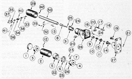
4T2. Description of the left training handle assembly. The left training handle assembly operates
the prism tilt mechanism by the movement of the
revolving grip, and is interconnected with an
appropriate mechanism in the eyepiece skeleton
assembly (Figure 4-28). It is further inter-connected by shifting wire tapes to the prism
tilt mechanism in the skeleton head assembly
(Figure 4-17) for elevation and depression of
the head prism (55).
It is equipped with a spring detent to hold the
line of sight at elevations of 14 degrees and 44 degrees above
horizontal. The detent facilitates observation of
the entire sky. This is done by placing the
periscope in low power and observing in three
zones with the line of sight set respectively at 1)
14 degrees elevation; 2) 44 degrees elevation; and 3) full, or
74.5 degrees, elevation. If the periscope is rotated a full
revolution in azimuth in each position, the
entire sky is seen with a minimum of overlap
between the zones. The detent may be rendered
inoperative by rotating the plunger release knob
(35, Figure 4-43). Figure 4-43 shows the left
training handle assembly. All bubble numbers
in Sections 4J2, 3, and 4 refer to Figure 4-43
unless otherwise specified.
Main body stop adjusting screws, also segment stop adjusting screw lockscrews
26
P-1389-7
4
Main body stop and segment stop adjusting screws
27
P-1408-3
1
Hinge bracket
28
P-1420-1
1
Handle hinge
29
P-1420-2
1
Fixed grip
30
P-1420-3
1
Revolving grip shaft
31
P-1420-4
1
Main body stop
32
P-1420-5
1
Main body stop segment
33
P-1420-6
1
Detent plunger
34
P-1420-7
1
Detent plunger housing
35
P-1420-8
1
Detent plunger release knob
36
P-1421-1
1
Detent plunger spring retaining bushing
37
P-1421-2
1
Detent plunger retaining cap
38
P-1421-3
1
Detent plunger spring
39
P-1421-4
2
Main body strip segment lockscrews
40
P-1421-5
1
Detent plunger release knob lockscrew
41
P-1421-6
1
Detent plunger retaining cap lockscrew
42
P-1421-7
1
Fixed grip lockscrew
a. Revolving grip. The revolving grip (2)
is made of brass tubing and is 3 9/16 inches in
length. The periphery is rough diamond knurled
to offer the observer a firm grip. Both ends of the
knurled periphery are relieved with a small
radius, and are provided with counterbored
sections of varying depth.
The outer counterbored end carries an outer
collar (3), a press fit in the counterbored section,
and an end cap (1) which is also a press fit in
the outer part of this same counterbored
section. A reamed clearance hole in the revolving
grip and the outer collar (3) is provided for the
lockscrew (12).
The inner counterbored end carries an inner
collar (5), a press fit in this counterbored
section.
b. Revolving grip outer collar. The revolving grip outer collar (3) is made of composition
brass and is cylindrical. The periphery is a press
fit in the outer counterbored section end in the
revolving grip (2). It has a reamed hole in
the center axis, a sliding fit on the revolving grip
shaft (30). A reamed hole in this collar coinciding
with the reamed hole in the revolving grip wall
accommodates a lockscrew (12) which screws
into the tapped hole in the revolving grip shaft
(30). This lockscrew secures the revolving grip
and the other collar to the shaft for its operation
c. Revolving grip end cap. The revolving
grip end cap (1) is made of brass rod and is
cylindrical. The large narrow shoulder flange
diameter coincides with the diameter of the
outer end radius shoulder of the revolving grip
(2) when the undercut shoulder is pressed into
the outer end counterbored section in the revolving grip. The outer sharp corner of the large
narrow shoulder flange is rounded off. This end
cap covers the outer part of the revolving grip,
thus preventing the entry of foreign matter.
The small drilled hole in the center axis serves
as an air release hole as the revolving grip is
assembled on the revolving grip shaft (30).
d. Revolving grip inner collar. The revolving grip inner collar (5) is made of composition
brass and is cylindrical. The periphery is a
press fit in the inner end counterbored section
of the revolving grip (2). It has a reamed hole
and counterbored section. The reamed hole is a
193
sliding fit on the revolving grip shaft (30), while
the counterbored section allows clearance for
the segment stop (7) and the protruding semicircular section of the fixed grip outer collar (4).
The side face of this inner collar (5) is provided
with a tapped hole to carry an index ring
actuating screw (22). The head of this screw
projects from the side face into the elongated
circumferential recess in the index ring (6).
This screw head, turning with the revolving
grip, carries the index ring for all degrees of
elevation and depression.
e. Fixed grip. The fixed grip (29) is made of
brass tubing and is 3 3/4 inches in length. The
periphery is rough diamond knurled to offer
the observer a firm grip. Both ends of the
knurled periphery are relieved. The inner end has
a small radius, while the outer end is provided
with the same type of radius except that it has
an undercut shoulder 7/32 inch in length. This
undercut shoulder diameter conforms to the
diameter of the index ring (6) and has the stationary index line engraved in its shoulder at
assembly.
The counterbored section in the outer end
carries the large shoulder section of the outer
collar (4), a press fit in this counterbored section.
The inner end is counterbored a depth of 1 1/2
inches, and is a sliding fit on the alignment
support section of the handy hinge (28). It
is secured on this alignment support section
with a lockscrew (42), which extends from the
tapped hole in the fixed grip and further into
the tapped hole in the alignment support section
of the handle hinge (28).
Directly opposite this tapped hole, a large
tapped hole is located outward with an approximate variance of 9/16-inch counter distance.
This tapped hole carries the detent plunger
housing (34).
f. Fixed grip outer collar. The fixed grip
outer collar. (4) is made of composition brass
and is 1 3/8 inches in length. It is cylindrical,
and has a reamed hole in its center axis, a
sliding fit on the revolving grip shaft (30).
The large shoulder section is a press fit in the
fixed grip (29). The undercut shoulder section
projects outward from the outer end of the fixed
grip, and is provided with a diameter of 1 1/2
inches. It carries the index ring (6) of a sliding
fit, taking up 5/16 inch of its shoulder length.
The remaining undercut shoulder section
extends into the counterbored section in the
revolving grip inner collar (5) The outer part
of the undercut shoulder has a cutaway semicircular section. The remaining semicircular
section serves as a segment stop foundation.
This section is provided with two tapped holes
on opposite sides perpendicular to the split and
in the center of the split wall thickness, for the
insertion of two segment stop adjusting screws
(26). The projecting part of each tapped hole
in the remaining periphery is recessed to provide
clearance for the insertion of a screwdriver
blade. The adjusting screws, project into the
milled-out part of the semicircular section to
contact the segment stop (7) attached to the
revolving grip shaft (30) for adjustment of the
index ring (6).
The side face of the semicircular projection
section is provided with opposite tapped holes
in the centerline and at a perpendicular plane
to the adjusting screws (26) for two segment
stop adjusting screw lockscrews (25). After
adjustments have been made with the adjusting
screws (26), they are secured with these two
lockscrews (25) to maintain the adjustments.
g. Revolving grip shaft. The revolving
grip shaft (30) is made of brass tubing and is
8.375 inches in length. This shaft is a sliding
fit in the reamed hole in the revolving rip
outer collar, (3) and the inner collar (5). It has a
tapped hole near its outer part to receive the
threaded part of the lockscrew (12) which projects inward from the clearance hole in the revolving grip (2) and its outer collar (3) for the
manipulation of the shaft upon the rotation of
the revolving grip (2).
Two tapped holes are provided in the shaft
for the segment stop lockscrews (23) at assembly
to secure the segment stop (7) for its proper
location in the counterbored section in the
revolving grip inner collar (5).
The inner part of the shaft is a sliding fit in
the reamed hole in the fixed grip outer collar
(4) and extends the entire length of the fixed
grip (29), a sliding fit in the large reamed hole
in the handle hinge (28). The inner end of the
194
shaft is counterbored a depth of 1 1/4 inches,
and serves as the alignment support section
for the outer end of the outer bevel gear clutch
shaft (8). This outer bevel gear clutch shaft
is a press fit in the counterbored section, and
is secured with a taper pin (13).
h. Index ring. The index ring (6) is made of
composition brass and is cylindrical, with a
width of 5/16 inch. The bored hole is a sliding fit
on the undercut shoulder of the fixed grip
outer collar (4). The periphery is engraved after
assembly to indicate 10 degrees depression, 0 degrees, 14 degrees, 44 degrees,
and 74.5 degrees elevation. The side face has a drilled
hole with a radially sawed slot to permit adjustment so that the index ring fits snugly on the
outer collar, providing sufficient friction so that
it does not slide free when elevating or depressing
the head prism by the rotation of the revolving
grip (2). A circumferential recess slot 0.375
inch in length is opposite the drilled hole.
The screw head of the index ring actuating
screw (22) projecting from the side face of the
revolving grip inner collar (5) engages in this
recess slot. This recess slot has 3/32-inch movement to coordinate with the correction made
with the adjusting screws (26) in the fixed
grip outer collar semicircular section (4). The
index ring fits between the inner face of
the revolving grip (2) and the outer face of the
fixed grip (29). The graduations are read when
they coincide with the stationary engraved
reference line on the fixed grip.
i. Segment stop. The segment stop. (7)
is made of composition brass. It consists of a
segment of approximately 60 degrees, with an inside
radius of 3/8 inch and an external radius of
9/16 inch. The outside radius conforms to the
contour of the undercut shoulder periphery
of the fixed grip outer collar (4), while the inside
radius conforms to the contour of the revolving
grip shaft periphery (30). It is secured to the
revolving grip shaft with two lockscrews (23).
These lockscrews are inserted into countersunk
clearance holes in the segment stop (7) and
screwed into tapped holes in the revolving grip
shaft (30) located in the counterbored section
of the revolving grip inner collar (5). The
segment stop is rotated with the revolving grip
shaft (30) and contacts the adjusting screws
(26) for full depression and elevation, plus
the compensation for the 3/32-inch lost motion
allowance.
j. Handle hinge. The handle hinge (28)
is made of cast phosphor bronze and is approximately 5 inches in length. It forms the outer
moving hinge part of the training handle
assembly. The outer part has a turned alignment support section 1 1/2 inches long, with a
narrow shoulder following this section. This
alignment support section serves as a stabilizing
support for the inner counterbored section of the
fixed grip (29), which is a snug sliding fit on
this alignment support section, and is secured
with a lockscrew (42). This lockscrew screws
into a tapped hole in the fixed grip (29) and
extends into the tapped hole in the alignment
support section wall.
The filleted cast section between the alignment
support section shoulder and the hinge section
wall forms a cylindrical extension between these
sections. It is provided with a raised boss in
the upper rear part to provide the necessary
wall thickness for the retention of a handle
detent plunger assembly.
The hinge section is similar in shape to an
apron, with the contour of the outer circumference uniform with the inner wall circumference
with a radius of approximately 140 degrees. The side
walls of the hinge section have projecting bosses
on the inner and outer faces, with a reamed hole
through the center axis of each boss offset from
the main horizontal centerline. The inner bosses
are a sliding fit over the side walls of the stationary hinge section of the hinge bracket (27).
The reamed holes in each side wall of the movable
hinge section carry a pivot screw (20), thus
serving as hinge pivots to carry the handle
hinge (28) through 90 degrees rotation.
The inner circumference of the apron wall
of the hinge section has sufficient clearance
over the stationary hinge section wall periphery
of the hinge bracket (27) to allow unrestricted
movement for the folding and unfolding of the
handle hinge (28). In the extended or unfolded
position, the lower flat face of the apron section
rests against the upper rectangular center face
of the hinge bracket (27).
The inner surface of the handle hinge is
provided with two counterbored sections in
195
the outer alignment support section, and with
two reamed holes inward from the counterbored
sections. The small and large counterbored
sections carry the main body stop (31). It is a
sliding fit in the small counterbored section
while the large counterbored section has sufficient clearance for the detent plunger (33).
The large counterbored section wall is provided
with a square broached hole for the square
section of the detent plunger (33) and an
opposite large clearance hole used for the
broaching of this square hole. A shallow tapped
hole in the same centerline and near the clearance hole receives the lockscrew (42).
The large reamed hole serves as an alignment
support section for the inner end of the revolving
grip shaft (30) of a sliding fit. The small reamed
hole extends through the inner circumference
of the cast apron wall. This small reamed hole
carries the stem section of the outer bevel gear
clutch shaft (8) secured to the revolving grip
shaft (30). The small reamed hole is counterbored
sufficiently in the inner circumference wall of
the apron section to allow a partially flat surface
for the assembly and the bearing contact of
the outer bevel gear clutch collar (9).
A reamed hole extends outward from the
inner circumference wall of the apron section,
into the raised boss provision of the cast filleted
section, a distance of 1 1/2 inches. This reamed
hole carries a handle detent plunger spring (17)
and a handle detent plunger (16). The plunger
is a sliding fit in this seamed hole, and is secured
by a lockscrew (18). This lockscrew extends
inward from the tapped hole in the rear hinge
section side wall for its protrusion into A the
axial recess keyway in the handle detent plunger
(16). The handle detent plunger rides on the
rear stationary hinge section side Wall periphery
of the hinge bracket (27) under spring tension
and engages in a 90 degrees V-groove notch to retain
the movable handle hinge (28) in the folded
or vertical position.
A small clearance hole is provided in the
centerline of the lower part of the apron wall
to allow sufficient clearance for the removal of
the outer bevel gear clutch shaft and collar
taper pin (24).
k. Main body stop. The main body stop
(31) is made of bronze and is 1.750 inches in
length. The bore is a sliding fit on the revolving
grip shaft (30). The external part is provided
with two shoulder sections. The small shoulder
section is a sliding fit in the small counterbored
section in the handle hinge outer part (28),
while the larger shoulder section has 1/8-inch
clearance in the large counterbored section
of the same outer part.
The outer part of the large shoulder section
has a semicircular section 3/8 inch wide removed
in the same manner as the fixed grip outer
collar (4). It is also provided with two adjusting
screws (26) and two adjusting screw lockscrews
(25) in the same manner for this remaining semicircular section. The adjusting screws project
into the milled-out semicircular part so that the
detent 90 degrees V-groove notches of 14 degrees and 44 degrees
elevation are synchronized with the 3/32-inch
lost motion of the revolving grip (2).
The 90 degrees V-groove notches are so located in
the large shoulder that they provide an indication
by means of the 90 degrees formed detent plunger (33)
under tension of a spring for the observer to
determine the location of the 14 degrees and 44 degrees
positions when observing the zenith.
1. Main body stop segment. The main
body stop segment (32) is made of bronze.
It consists of a segment 3/8 inch wide and approximately 165 degrees, with an inside radius of 3/8 inch
and an external radius of 39/64 inch. The inside
radius conforms to the contour of the revolving
grip shaft periphery (30), while the outside radius
is larger than the contour of the large shoulder
of the main body stop periphery (31). The
segment is secured to the revolving grip shaft
with two lockscrews (39). These lockscrews are
inserted in countersunk clearance holes in the
main body stop segment (32) and screwed
into tapped hole in the revolving grip shaft (30)
located in coincidence with the main body stop
semicircular protruding section (31). The main
body stop is rotated with the revolving grip
shaft and contacts the adjusting screws (26)
for the rotation of the main body stop (31)
for its use with the projecting detent plunger
(33) located in the square broached hole in the
handle hinge alignment support section (28).
m. Hinge bracket. The hinge bracket (27)
is made of cast phosphor bronze, with a rectangular base. The hinge section projects
196
outward from the rectangular base, surrounded
by a rectangular raised boss section. The
rectangular base and the hinge section form the
stationary half of the hinge. Four raised cylindrical bosses are provided with a clearance hole
for the hinge bracket (27) and are screwed into tapped holes in the left side of the eyepiece box
(11, Figure 4-29) to retain the hinge bracket.
The inner face of the rectangular base is
provided with a counterbored section and a
reamed hole, offset from the horizontal centerline. The reamed hole serves as a bearing for
the inner bevel gear clutch (14), while the counterbored section provides clearance over the
left training handle packing gland assembly
protruding stuffing box body flange (5, Figure
4-34) located in the eyepiece box. Two countersunk clearance holes and a tapped section are
provided in the face of the counterbored section.
These holes extend outward into both of the
hinge section side walls and their perpendicular
tapped holes for two pivot screw lockscrews
(21). These lockscrews secure the pivot screws
(20) when assembled in the hinge section
side walls.
The central part of the hinge section is
provided with a cylindrical raised boss, to carry
the shoulder of the inner bevel gear clutch (14).
Sufficient radius clearance is provided for
assembly and removal of the inner and outer
bevel gear clutches (14 and 15) and clearance
inside the side walls for the 90 degrees rotation of the
outer bevel gear clutch collar (9). The contour
of the outer circumference of the side walls and
the lower wall conforms to the inner circumference of the hinge section wall of the handle
hinge (28). The rear side wall is carried above
the upper flat wall approximately 1 1/16 inches
and is provided with a 90 degrees V-groove notch in
the same vertical centerline as the pivot screw
tapped hole. The 90 degrees V-groove notch serves
to retain the handle hinge (28) in the folded
position by means of the handle detent plunger
(16) under spring tension, and allows the handle
hinge to swing downward of its own gravity by
the force required to overcome the spring
pressure of the handle detent plunger spring
(17). The handle detent plunger rides on the
periphery of the rear side wall, as the handle
hinge is swung to the extended position. The
handle detent plunger (16) is then under full
tension and the spring (17) is fully compressed.
The inner face of each raised boss of the
handle hinge (28) side walls is a sliding fit over
the hinge section side walls of the hinge bracket
(27). The pivot screws (20) extending from the
opposite reamed holes in the handle hinge (28)
extend into the tapped holes in the hinge
section side walls of the hinge bracket (27) with
the medium shoulder face of each pivot screw
a metal to metal fit with the hinge section side
walls.
n. Pivot screws. The pivot screws (20)
are made of phosphor bronze and are 0.906
inch in length, with-the head section chromium
plated. They form hinge pins on which the
hinge section of the handle hinge (28) can be
swung through 90 degrees rotation. Each screw has a
slotted head section for a screwdriver blade.
The head section projects outward from each
side wall raised boss of the handle hinge (28).
The main body section is a snug fit in reamed
pivot holes in the hinge section side walls of the
handle hinge, with this shoulder resting against
the side wall faces of the hinge bracket hinge
section (27). The stub section is threaded and
engages in a tapped hole in each hinge section
side wall of the hinge bracket (27). The pivot
screws are secured with lockscrews (21) which
are inserted into countersunk clearance holes
in the counterbored section base of the hinge
bracket (27) and screwed into tapped holes
in each hinge section side wall to contact the
threaded stub section of the pivot screws.
o. Outer bevel gear clutch shaft. The
outer bevel gear clutch shaft (8) is made of
monel metal and is 3 inches in length. The large
diameter section is a pressed fit into the inner
counterbored section end of the revolving grip
shaft (30) and is secured with a taper pin (13).
The stem section is a sliding fit into the small
reamed hole in the handle hinge (28), and
receives an outer bevel gear clutch collar (9)
at the opposite end and the inner circumference
end of the apron wall and hinge section. The
outer bevel gear clutch collar (9) is secured to
the stem section of the shaft with a taper pin
(24) in the hinge section of the handle- hinge.
The square section of the shaft carries the outer
bevel gear clutch (15) against the spring tension
197
of the outer bevel gear clutch spring (10),
by means of a retaining screw (11). The retaining
screw extends into the tapped hole axis in the
square section of the shaft.
p. Outer bevel gear clutch collar. The
outer bevel gear clutch collar (9) is made of
phosphor bronze and is 0.656 inch in length.
It provides a container in which the outer bevel
gear clutch spring (10) is carried. It has a
reamed hole in its center axis with a counterbored section, and is secured to the stem section
of the outer bevel gear clutch shaft (8) with a
taper pin (24). The outer bevel gear clutch
spring (10) is carried over part of the stem
section and the square section of the outer bevel
gear clutch shaft (8). The spring places a constant tension against the hub face of the outer
bevel gear clutch (15).
q. Inner and outer bevel gear clutches.
The inner and outer bevel gear clutches (14
and 15) are made of phosphor bronze and are
chromium plated. Both the bevel gear sections
have the same diameter and number of teeth.
They are provided with 19 bevel teeth of 20
diametral pitch, and have a pitch cone line
angle of 45 degrees. Each is provided with a square
broached hole. The square broached hole and the
hub sections of the outer bevel gear clutch (15)
move axially in the outer bevel gear clutch collar
(9) against the outer bevel gear clutch spring
(10) on the square section of the outer bevel
gear clutch shaft (8).
The hub section of the inner bevel gear
clutch fits in the reamed hole axis of the hinge
bracket (27), and it extends farther on the square
section of the actuating shaft (11, Figure 4-36)
of the training handle packing gland assembly.
It extends simultaneously on the square section
of the shaft and in the counterbored recess in
the packing gland (8).
The inner and outer bevel gear clutches are
in mesh in either the folded or extended positions
by means of the outer bevel gear clutch spring
(10). In the folded position, both bevel gears are
in perpendicular relation to each other at 90 degrees,
with both 45 degrees pitch cone line angles. In the
extended position, both level gears act as a
universal jaw clutch, with all teeth engaged for
the operation of the prism tilt mechanism.
r. Detent plunger. The detent plunger (33)
is made of corrosion-resisting steel and is
1.180 inches in length. The detent section is
square and is provided with a 90 degrees V-formed
point for engagement into the 90 degrees V-groove
notches in the main body stop large shoulder
periphery (31). The square detent section is a
sliding fit in the square broached hole in the
alignment support section in the handle hinge
(28). The large shoulder section rests against
the flat spot face in the handle hinge alignment
support section periphery, and moves axially
in the detent plunger housing (34) against the
tension of the detent plunger spring (38).
The small shoulder serves to center the detent
plunger spring concentrically, while the stem
shaft extends through the reamed hole in the
detent plunger spring retaining bushing (36),
detent plunger release knob (3S), and the detent
plunger retaining cap (37).
s. Detent plunger housing. The detent
plunger housing (34) is made of brass rod 5/8 inch
in length and chromium plated. The center axis
is provided with a reamed hole to carry the
large shoulder of the detent plunger (33) axially
and has sufficient space for the detent plunger
spring (38). The outer end has a threaded
counterbored section of shallow depth to
receive the threaded periphery shoulder of the
detent plunger spring retaining bushing (36).
The inner end periphery is threaded a short
distance, screws into the large tapped hole in
the fixed rip (29), and rests against the flat
spot face in the handle hinge alignment support
section periphery (28). The outer face is provided
with two opposite slots for a special wrench. A
tapped hole in the wall periphery accommodates
a detent plunger retaining bushing lockscrew
(40), the head of which projects from the
wall periphery the thickness of the detent
plunger release knob undercut shoulder (35).
This projecting lockscrew head offers the detent
plunger release knob a contact support for the
engagement or disengagement of the detent
plunger (33) by turning the knob, thus allowing
it to raise or lower the detent plunger.
t. Detent plunger spring retaining bushing. The detent plunger spring retaining bushing (36) is made of phosphor bronze and is
0.445 inch in length. It is provided with a large
198
threaded periphery shoulder with an undercut
alignment support section shoulder which serves
as a guide for the detent plunger spring (38) in
the inner circumference of the detent plunger
housing (34). The alignment support section
extends into the detent plunger housing (34)
to serve as an outer stop for the detent plunger
(33). The threaded periphery of this bushing
screws into the threaded counterbored section
in the detent plunger housing (34) compressing
the degrees detent plunger spring (38). Two opposite
holes are provided in the shoulder for the insertion of a special wrench. The center axis has a
reamed hole to accommodate the detent plunger
stem section. This reamed hole guides and supports the detent plunger stem section.
u. Detent plunger spring. The detent
plunger spring (38) is made of spring tempered
phosphor-bronze wire having a free length of
0.870 inch and a coiled diameter of 0.280 inch.
The spring is compressed in the detent plunger
housing (34) by the detent plunger spring retaining bushing (36) and forces the detent
plunger (33) into the 90 degrees V-groove notches in
the main body stop large shoulder periphery
in the engaged position, for 14 degrees and 44 degrees line
of sight of the head prism (55, Figure 4-17).
v. Detent plunger release knob. The detent
plunger release knob (35) is made of brass rod
1/2 inch in length and, chromium plated. The
large shoulder periphery is knurled, having the
sharp corner rounded off. The center axis has a
reamed hole for the stem section of the detent
plunger (33). It is provided with a counterbored
section, a sliding fit on the detent plunger
housing (34), leaving a nominal outer side wall.
The undercut shoulder side face is provided with
a shallow notch which rides in spring contact
with the lockscrew head (40). When the shallow
notch is in contact with the lockscrew head,
the detent plunger is engaged for operation.
The rotation of the knob causes the disengagement of the detent plunger (33).
w. Detent plunger retaining cap. The
detent plunger retaining cap (37) is made
of corrosion-resisting steel material. A reamed
hole of shallow depth is located in its center
axis, a sliding fit on the upper part of the
detent plunger stem section and is secured with
a lockscrew (41). This lockscrew is screwed into
a tapped hole in the retaining cap wall and
extends into the spotted recess in the detent
plunger stem section. The outer face of the retaining cap has a radius, thus breaking the
sharp corners. The cap serves to carry the
detent plunger (33) upward upon the rotation
of the detent plunger release knob (35) against
the tension of the detent plunger spring (38).
x. Handle detent plunger spring. The
handle detent plunger spring (17) is made of
spring steel and has a free length of 1 3/4 inches.
The spring is coiled to a diameter of 9/32 inch,
and is a loose fit in the reamed hole of 1-inch
depth in the handle detent plunger (16). The
spring maintains a constant tension against the
handle detent plunger (16) which is engaged in
the 90 degrees V-groove notch in the rear side wall
periphery of the hinge bracket hinge section (27)
in the folded position. In the extended position,
the spring is under full compression.
y. Handle detent plunger. The handle
detent plunger (16) is made of corrosion resisting steel and is 1.593 inches in length.
The outer end is provided with a reamed hole
1 inch deep, serving as a guide for the handle
detent plunger spring (17). The inner end of
the plunger is provided with a 90 degrees V-formed
detent point for engagement in the 90 degrees V-groove
notch in the hinge bracket hinge section side
wall periphery (27) in the folded position.
The external diameter is a sliding fit in the
reamed hole in the rear raised boss section,
between the hinge section and the alignment
support section, and a part of the filleted circular
section of the handle hinge. The plunger, under
heavy tension, projects outward from the apron
wall of the handle hinge (28). A shallow keyway
is provided at a perpendicular plane to the 90 degrees
V-formed detent point. This keyway receives
the undercut shoulder of the retaining screw
(18) which extends inward from the tapped
hole in the rear side wall face of the handle
hinge (28). The undercut part of the retaining
screw (18) engaged in the keyway prevents
loss and injury upon disassembly of the handle
hinge (28) in case the handle detent plunger is
improperly secured.
The handle detent plunger (16) and spring (17)
serve as a friction catch to retain the handle
hinge in the folded position, by the engagement
199
of the 90 degrees V-formed detent point in the 90 degrees
V-groove notch located in the rear hinge section
side wall of the hinge bracket (27) under heavy
tension.
4T3. Disassembly of the left training handle assembly. The left training handle assembly is disassembled in the following manner:
1. Remove they detent plunger assembly from
the fixed grip (29), unscrewing the detent plunger
housing (34) from the large tapped hole in the
fixed grip.
2. Remove the lockscrew (41), unscrewing
it from the detent plunger retaining cap (37).
Remove the retaining cap.
3. Remove the detent plunger release knob
(35), the detent plunger (33), and the detent
plunger spring (38) from the inner end of the
detent plunger housing (34).
4. Remove the detent plunger spring retaining bushing (36), using a special wrench
inserted in the opposite holes to unscrew it
from the detent plunger housing (34).
5. Remove the lockscrew (40), unscrewing
it from the detent plunger housing (34).
6. Remove the lockscrew (12), unscrewing
it from the tapped hole in the revolving grip
shaft (30), and carrying it out of the revolving
grip (2) and outer collar clearance holes (3).
7. Slide the revolving grip (2) off the revolving grip shaft (30), carrying with it the revolving
grip end cap (1), outer collar (3), inner collar
(5), and index ring actuating screw (22).
8. Remove the two lockscrews (23) from the
segment stop (7), unscrewing them from tapped
holes in the revolving rip shaft (30). Remove
the segment stop (7).
9. Remove the lockscrew (42) from the fixed
grip (29), unscrewing it from the tapped holes
in the handle hinge alignment support section
(28) and the fixed grip.
10. Remove the fixed grip (29 with the index
ring (6) on the fixed grip outer collar (4), sliding
it off the handle hinge alignment support section
(28), and carrying it off the, revolving grip
shaft (30).
11. Remove the index ring (6), sliding it from
the fixed grip outer collar (4).
12. Remove the two lockscrews (39) from the
main body stop segment (32), unscrewing
these lockscrews from tapped holes in the
revolving grip shaft (30). Remove the main
body stop segment (32).
13. Remove the main body stop (31) sliding
it off the revolving grip shaft (30).
14. Remove the two pivot screw lockscrews
(21), unscrewing them from contact with
the two pivot screws (20) and the tapped holes
in each hinge section side wall of the hinge
bracket (27) in its inner counterbored recess
in the base.
15. Swing the handle hinge to the extended
position. Only in this position is there sufficient
clearance for the removal of the outer bevel
gear clutch (15) with the remaining assembly of
the handle hinge (28) from the hinge bracket (27).
16. Remove the two pivot screws (20),
unscrewing them from the tapped holes in the
hinge section side walls of the hinge bracket
(27). Remove the handle hinge assembly from
the hinge bracket (27).
17. Remove the inner bevel gear clutch (14),
sliding it out of the hinge bracket (27).
18. Remove the retaining screw (11), unscrewing it from the tapped hole in the outer bevel
gear clutch shaft (8). Remove the outer bevel
gear clutch (15) and the outer bevel gear clutch
spring (10), sliding them off the square section
of the outer bevel gear clutch shaft (8).
19. Rotate the revolving rip shaft (30)
until the small end of the taper pin (24) is
lined up with the drift clearance hole in the
handle hinge wall (28).
20. Place a drift punch of suitable size
in the handle hinge (28) clearance hole.
21. Drive the taper pin (24) from the outer
bevel gear clutch collar (9) and the outer bevel
gear clutch shaft (8).
22. Remove the outer bevel gear clutch
collar (9) from the outer bevel gear clutch
shaft (8).
200
23. Remove the revolving grip shaft (30)
and the assembled outer bevel gear clutch shaft
(8) from the handle hinge (28).
24. Do not disassemble the outer bevel gear
clutch shaft (8) from the revolving grip shaft
(30). Leave them secured with the taper pin (13).
25. Remove the retaining screw (18), unscrewing it from its engagement in the keyway
in the handle detent plunger (16), and the tapped
hole in the hinge section rear side wall of the
handle hinge (28).
26. Remove the handle detent plunger (16)
and the handle detent plunger spring (17)
from the reamed hole in the hinge section inner
circumference wall of the handle hinge (28).
27. The two main body stops, the two segment stop adjusting screws (26), and the
four lockscrews (25) are not altered during
disassembly.
4T4. Reassembly of the left training, handle assembly. The left training handle assembly is reassembled in the following manner:
1. Lubricate lightly all rotating parts with
Lubriplate No. 110 as the reassembly procedure
is followed.
2. Place the handle detent plunger spring
(17) in the handle detent plunger (16).
3. Place the handle detent plunger (16)
and its spring (17) in the reamed hole in the
rear inner circumference of the handle hinge
(28). Rotate the handle detent plunger until
the keyway is located to the rear, and its detent
point is lying in a horizontal plane so that the,
retaining screw (18) engages in the keyway.
4. Insert the retaining screw (18), screwing
it into the tapped hole so that its undercut
shoulder engages into the keyway in the handle
detent plunger (16).
5. Place the assembled outer bevel gear
clutch shaft (8) and revolving grip shaft (30)
in their respective teamed holes in the handle
hinge (28).
6. Place the outer bevel gear clutch collar
(9) on the outer bevel gear clutch shaft (8).
7. Align the taper pin holes in the outer
bevel gear clutch shaft (8) and collar (9).
8. Insert and secure the taper pin (24)
from the open hinge section side of the handle
hinge (28).
9. Place the outer bevel gear clutch spring
(10) over the outer bevel gear clutch shaft (8)
and in the counterbored section of the outer
bevel gear clutch collar (9).
10. Place the outer bevel gear clutch (15)
on the square section of the outer bevel gear
clutch shaft (8) with the reference marks in
line.
11. Compress the outer bevel gear clutch
spring (10) by pressing inward on the outer
bevel gear clutch (15) for the insertion of the
retaining screw (11). Insert the retaining screw
(11), screwing it into the square section axis
tapped hole in the outer bevel gear clutch
shaft (8).
12. Check the outer bevel gear clutch (15)
for free spring movement.
13. Place the inner bevel gear clutch (14)
in the reamed hole in the cored hinge section
of the hinge bracket (27).
14. Holding the handle hinge assembly in
the extended position, carry the outer bevel
gear clutch (15) through the cored clearance
section in the hinge bracket (27).
15. Check the reference marks of the inner
bevel gear clutch (14) tooth with its mating
reference mark in the outer bevel gear clutch
(15). Engage the gear teeth of the inner and
outer bevel gear clutches, carrying the hinge
section of the handle hinge (28) over the hinge
section of the hinge bracket (27).
16. Apply downward pressure to the handle
hinge (28); the handle detent plunger (16)
resting on the hinge section side wall periphery
of the hinge bracket (27) compresses the spring
fully for the insertion of the two opposite side
pivot screws (20).
17. Insert the two pivot screws (20) in the
opposite side walls of the handle hinge (28),
check the reference marks, and screw them into
tapped holes in the hinge section side walls
of the hinge bracket (27).
18. Secure both pivot screws (20) with the
lockscrews (21), insert them in body clearance
201
holes, and screw them in the tapped hole section
in each of the hinge section side walls of the
hinge bracket (27) from its inner counterbored
recess in the base. The lockscrews contact the
pivot screw threaded sections.
19. Place the main body stop (31) on the
revolving grip shaft (30), sliding it into the small
and large counterbored sections in the alignment
support section of the handle hinge (28).
20. Place the main body stop segment (32)
on the revolving grip shaft (30); secure it opposite the semicircular projecting section of the
main body stop (31) to the revolving grip shaft
(30) with two lockscrews (39). These lockscrews
are inserted in countersunk clearance holes in
the main body stop segment (32) and screwed
into tapped holes in the shaft.
21. Place the fixed grip (29) on the revolving
grip shaft (30), sliding it on the alignment
support section of the handle hinge (28).
22. Align the tapped lockscrew holes and
insert the lockscrew (42). This lockscrew screws
the tapped hole in the fixed grip (29) and the
handle hinge alignment support section wall (28).
23. Place the index ring (6) over the revolving
grip shaft (30) and on the undercut shoulder
section of the fixed grip outer collar (4). It
should fit snugly on the shoulder of this collar.
24. Place the segment stop (7) on the revolving grill shaft (30). Secure it opposite
the semicircular projecting section of the fixed
grip outer collar (4) to the revolving grip shaft
(30) with two lockscrews (23). These lockscrews
are inserted in countersunk clearance holes in
the segment stop (7) and screwed into tapped
holes in the shaft.
25. Place the revolving grip (2) on the revolving grip shaft (30), carrying with it the
outer and inner collars (3 and 5), the end cap
(1), and the index ring actuating screw (22).
Engage the actuating screw head in the elongated
radial recess ins the outer face of the index
ring (6).
26. Insert the lockscrew (12), carrying it in
the clearance holes of the revolving grip (2)
and the outer collar (3), and screwing it into
the tapped hole in the revolving grip shaft (30).
22. Rotate the revolving grip (2) until the
index ring (6) with the graduated line of 74.5 degrees
is in full elevated position. This graduated line
on the index ring should coincide with the
stationary index line on the fixed grip (29).
Correct the insufficient or over-travel of the index
ring by means of two segment stop adjusting
screws (26). The front adjusting screw corrects
for elevation, while the rear adjusting screw
corrects for depression. Follow the same procedure for 10 degrees, or full depression.
28. Insert the detent plunger release knob
lockscrew (40) in the tapped hole in the detent
plunger housing (34).
29. Insert the detent plunger spring retaining
bushing (36), screwing it in the threaded counterbored section in the detent plunger housing
(34), using a special wrench inserted in the
opposite holes in its large shoulder face.
30. Place the detent plunger spring (38)
in the detent plunger housing (34) from the
inner end.
31. Place the detent plunger (33) in the detent
plunger spring (38), detent plunger housing
(34), and in the reamed hole in the detent
plunger spring retaining bushing (36).
32. Place the lockscrew (41) in the tapped
hole in the detent plunger retaining cap (37).
33. Place the detent plunger release knob
(35) and the detent plunger retaining cap (37)
on the protruding stem of the detent plunger
(33). Holding the detent plunger release knob
(35) and the end of the detent plunger (33),
compress the detent plunger spring (38), carrying
the stem section of the detent plunger outward
and securing it with the lockscrew (41). The
lockscrew contact a spotted face in the detent
plunger stem section.
34. Place the detent plunger assembly in
the fixed grip (29). The reference punch mark
on the square part of the detent plunger should
face upward. Insert the square part of the detent
plunger (33) in the square broached hole in
the handle hinge (28). Screw the detent plunger
housing (34) threaded periphery into the tapped
hole in the fixed grip (29).
35. Rotate the detent plunger release knob
(35) to the engagement position.
202
36. Rotate the revolving grip slowly to observe
the detent action. The detent should engage at
14 degrees and 44 degrees elevation. Correct insufficient or
excessive travel of the zone graduation of the
index ring (6) by means of two adjusting screws
in the main body stop (31). To make the necessary adjustments, follow Steps 1 to 12 of the
disassembly procedure. The detent cannot be
adjusted until the index ring has been corrected
for elevation and depression.
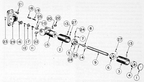
4T5. Description of the right- training handle
assembly. The right training handle assembly
operates the change of power mechanism by the
movement of the revolving grip (3, Figure 4-44)
and its interconnection with an appropriate
mechanism in the eyepiece skeleton assembly
(Figure 4-28). It is further interconnected by
shifting wire tapes to the change of power
mechanism in the skeleton head assembly (Figure
4-17) for changing from high-power to low-power
magnification and vice versa. The right training
handle assembly is similar to the left training
handle assembly, and the variance of similar
parts is described only briefly. Figure 4-44
shows the right training handle assembly. All
bubble numbers in Sections 4T5, 4T6, 4T7 refer
to Figure 4-44 unless otherwise specified.
Outer bevel gear clutch shaft and collar taper pin
26
P-1310-39
2
Segment stop adjusting screw lockscrews
27
P-1389-6
2
Power indicating screws
28
P-1389-7
2
Segment stop adjusting screws
29
P-1408-4
1
Hinge bracket
a. Revolving grip. The revolving grip (3)
is made of the same material and diameter
as the left revolving grip (2, Figure 4-43),
except that it is longer, and is provided with
an undercut shoulder at the inner end. This
shoulder has two graduated index lines, the
upper has the letters H.P. engraved below it,
while the lower has the letters L.P. engraved
above it. These two graduated lines, when
in coincidence with the stationary index lines
on the fixed grip (2), visually indicate the power
being used by the observer. A power indicating
screw (27) is inserted in this undercut shoulder
section to indicate low power when in coincidence
with a similar power indicating screw (27) inserted in the fixed grip (2). When these screws
are separated, the indication magnification is
high power.
The counterbored section in the inner end
is shallower in depth and receives the revolving
grip inner collar (6), while the counterbored
section in the outer end is the same as that
which receives the revolving grip outer collar
(4) and the revolving grip end cap (1).
b. Revolving grip outer collar. The revolving grip outer collar (4) is identical to
the left revolving grip outer collar (3, Figure
4-43), and serves the same purpose and function
in the outer end of the revolving grip (3). It
is secured to the revolving grip shaft (9) with a
lockscrew (13) in the same manner.
203
Figure 4-44. Right training handle assembly.
c. Revolving grip end cap. The revolving
grip end cap (1) is identical to the left revolving
grip end cap (1, Figure 4-43). It serves the
same purpose and function in the outer end
of the revolving grip (3).
d. Revolving grip inner collar. The revolving grip inner collar (6) is made of the
same material and has the same external diameter, reamed hole diameter, and counterbored
section diameter and depth as the left revolving
grip inner collar (5, Figure 4-43). It differs in
length and has no tapped hole for an index ring
actuating screw (22, Figure 4-43). The counterbored section receives the projecting shoulder
and semicircular section of the fixed grip outer
collar (5) and the segment stop (7) on the opposite side of the semicircular projecting section
which is secured to the revolving grip shaft (9)
with two lockscrews (24).
e. Fixed grip. The fixed grip (2) is almost
identical to the left fixed grip (29, Figure 4-43)
except that it has no tapped hole for the insertion
of a detent plunger assembly. The undercut
shoulder is provided with a graduated stationary
index line and a power indicating screw (29)
at assembly.
The counterbored section in the outer end
carries the fixed grip outer collar (5) of a press
fit, while the counterbored section in the inner
end is a snug sliding fit on the alignment support
section of the handle hinge (15). It is secured
with a lockscrew (13) in the manner shown in
Figure 4-43.
f. Fixed grip outer collar. The fixed grip
outer collar (5) is similar to the left fixed grip
outer collar (4, Figure 4-43) except for the length
of the undercut shoulder. The semicircular
section is provided with two segment stop
adjusting screws (28) and two adjusting screw
lockscrews (26) in the same manner. The
adjusting screws (28) contact the segment stop
(7) attached to the revolving grip shaft (9)
for correcting insufficient or excessive travel
of the segment stop (7) in relation to the high and low-power graduated index lines.
g. Revolving grip shaft. The revolving
grip shaft (9) is identical to the left revolving
grip shaft (30, Figure 4-43). This shaft is a
sliding fit in the reamed hole in the revolving
grip outer collar (4) and the inner collar (6).
It has a tapped hole near its outer end to receive
the threaded section of the lockscrew (13) which
is inserted in a clearance hole in the revolving
grip (3) and outer collar (4) for the manipulation
of the shaft upon the rotation of the revolving
grip (3).
204
Two tapped holes are provided in the shaft
for the segment stop lockscrews (24) at assembly,
to secure the segment stop (7) for its proper
location in the counterbored section in the
revolving grip inner collar (6).
The inner end of the shaft is a sliding fit
in the reamed hole in the fixed grip outer collar
(5), and extends the entire length of the fixed
grip (2), a sliding fit into the large reamed hole
in the handle hinge (15). The inner end of the
shaft carries the large shoulder section of the
outer bevel gear clutch shaft (8) of a press fit,
and is secured with a taper pin (14).
h. Outer bevel gear clutch shaft. The
outer bevel gear clutch shaft (8) is identical
to the left outer bevel gear clutch shaft (8,
Figure 4-43) serving the same purpose and
function. It is secured to the revolving grip
shaft (9) with a taper pin (14).
i. Segment stop. The segment stop (7)
is similar to the left segment stop (7, Figure 4-43)
and is approximately 114 degrees. It is secured to
the revolving grip shaft (9) with two lockscrews
(24). These lockscrews are inserted in countersunk clearance holes in the segment stop (7)
and screwed into tapped holes in the revolving
grip shaft (9) located in the counterbored section
in the revolving grip inner collar (6). The
segment stop is rotated with the revolving grip
shaft (9) and contacts the adjusting screws (28)
for high and low power,
j. Handle hinge. The handle hinge (15)
is almost identical to the left handle hinge,
(28, Figure 4-43) except that it is designed to
be used by the opposite hand. The alignment
support section carries the fixed grip (2) on
its periphery and is secured with a lockscrew
(13) in the same manner. However, the alignment support section of the handle hinge does
not have the two countered sections for the
main body stop (31) used in the left handle
hinge (28, Figure 4-43) the square broached hole,
and the opposite clearance hole.
k. Hinge bracket. The hinge bracket (29)
is identical to the left hinge bracket (27, Figure
4-43) except that it is designed to be used by
the opposite hand.
l. Pivot screws. The pivot screws (22) are
identical to the left pivot screws (20, Figure
4-43). They serve the same purpose and function
for the handle hinge (15) and hinge bracket (29),
and are secured with two lockscrews (23).
m. Outer bevel gear clutch collar. The
outer bevel gear clutch collar (10) is identical
to the left outer bevel gear clutch collar (9,
Figure 4-43).
n. Inner and outer bevel gear clutches.
The inner and outer, bevel gear clutches (16
and 17) are identical to the left inner and
outer bevel gear clutches (14 and 15, Figure
4-43).
o. Handle detent plunger spring. The
handle detent plunger spring (19) is identical
to the left handle detent plunger spring (17,
Figure 4-43), serving the same purpose and
function in the handle hinge (15).
p. Handle detent plunger. The handle
detent plunger (18) is identical to the left
handle detent plunger (16, Figure 4-43), serving
the same purpose and function in the handle
hinge (15) and hinge bracket (29). It is secured
with a retaining screw (20) in the same manner.
4T6. Disassembly of the right training handle. The
right training handle is disassembled in the
following manner:
1. Remove the lockscrew (13), unscrewing
it from the revolving grip shaft (9), and carrying
it out from the revolving grip (3) and outer
collar (4) clearance holes.
2. Remove the revolving grip (3), sliding
it off the revolving grip shaft (9), and carrying
with it the revolving grip end cap (1), revolving
grip outer collar (4), and the revolving grip
inner collar (6).
3. Remove the two lockscrews (24) from the
segment stop (7), unscrewing them from the
tapped holes in the revolving grip shaft (9).
Remove the segment stop (7).
4. Remove the lockscrew (13) from the
fixed grip (2), unscrewing it from the tapped
holes in the handle hinge alignment support
section (15) and the fixed grip.
5. Remove the fixed grip (2) with the fixed
grip outer collar (5), sliding it off the handle
hinge alignment support section 15) and carrying it off the revolving grip shaft (9).
205
6. Remove the two pivot screw lockscrews
(23), unscrewing them from contact with the
two pivot screws (22) and the tapped holes in
each hinge section side wall of the hinge bracket
(29) in the bottom counterbored recess.
7. Swing the handle hinge to the extended
position. Only in this position is there sufficient
clearance for the removal of the outer bevel
gear clutch (17) with the remaining assembly
of the handle hinge (15) from the hinge bracket
(29).
8. Remove the two pivot screws (22),
unscrewing them from the tapped holes in the
hinge section side walls of the hinge bracket (29).
Remove the handle hinge assembly from the
hinge bracket (29).
9. Remove the inner bevel gear clutch (16),
sliding it out of the hinge bracket (29).
10. Remove the retaining screw (12), unscrewing it from the tapped hole in the outer
bevel gear clutch shaft (8). Remove the outer
bevel gear clutch (17) and the outer bevel
gear clutch spring (11), sliding them off the
square section of the outer bevel gear clutch
shaft (8).
11. Rotate the revolving grip shaft (9)
until the small end of the taper pin (25) is
in line with the drift clearance hole in the handle
hinge wall (15).
12. Place a drift punch of suitable size
in the clearance hole.
13. Drive the taper pin (25) from the outer
bevel gear clutch collar (10) and the outer
bevel clutch shaft (8)
14. Remove the revolving grip shaft (9)
and the assembled outer bevel gear clutch
shaft (8) from the handle hinge (15).
15. Do not disassemble the outer bevel gear
clutch shaft (8) from the revolving grip shaft
(9). Leave them secured with a taper pin (14).
16. Remove the retaining screw (20), unscrewing it from its engagement in the keyway
in the handle detent plunger (18) and the tapped
hole in the hinge section rear side wall of the
handle hinge (15).
17. Remove the handle detent plunger (18)
and its spring (19) from the reamed hole in
the hinge section inner circumference wall of
the handle hinge (15).
18. The two segment stop adjusting screws
(28) and the two lockscrews (26) are not altered
during disassembly.
19. The power indicating screws (27) are
not removed from the revolving and fixed grips
(3 and 2).
4T7. Reassembly of the right training handle
assembly. The right training handle assembly
is reassembled in the following manner:
1. Lubricate lightly all rotating parts with.
Lubriplate No. 110 as the reassembly procedure
is followed.
2. Place the handle detent plunger spring
(19) in the handle detent plunger (18).
3. Place the handle detent plunger (18)
and its spring (19) in the reamed hole in the
rear inner circumference of the handle hinge
(15). Rotate the plunger until the keyway is
located to the rear, and its detent point is lying
in a horizontal plane so that the retaining screw
(20) engages in the keyway.
4. Insert the retaining screw (20), screwing
it into the tapped hole with its undercut shoulder
engaging into the keyway in the handle detent
plunger (18).
5. Place the assembled outer bevel gear
clutch shaft (8) and the revolving grip shaft
(9) in their respective reamed holes in the
handle hinge (15).
6. Place the outer bevel gear clutch collar
(10) on the outer bevel gear clutch shaft (8).
7. Align the taper pin holes in the outer
bevel gear clutch shaft (8) and collar (10).
8. Insert and secure the taper pin (25),
inserting it from the open hinge section side
of the handle hinge (15).
9. Place the outer bevel gear clutch spring
(11) on the outer bevel gear clutch shaft (8)
and in the counterbored section in the outer
bevel gear clutch collar (10).
10. Place the outer bevel gear clutch (17)
on the square section of the outer bevel gear
clutch shaft (8), with the reference marks in
line.
206
11. Compress the outer bevel gear clutch
spring (11) by pressing inward on the outer
bevel gear clutch (17) for the insertion of the
retaining screw (12). Insert the retaining screw
(12), screwing it into the square section tapped
hole in the outer bevel gear clutch shaft (8).
12. Check the outer bevel gear clutch (17)
for free spring movement.
13. Place the inner level gear clutch (16)
in the reamed hole in the cored hinge section
of the hinge bracket (29).
14. Holding the handle hinge assembly in
the extended position, carry the outer bevel
gear clutch (17) through the cored clearance
section in the hinge bracket (29).
15. Check the reference marks of the inner
bevel gear clutch (16) tooth with its mating
reference mark in the outer bevel gear clutch
(17). Engage the gear teeth of the inner and
outer bevel gear clutches, carrying the hinge
section of the handle hinge (15) over the hinge
section side walls of the hinge bracket (29).
16. Apply downward pressure to the handle
hinge (15) with the handle detent plunger (18)
resting on the hinge section side wall periphery
of the hinge bracket (29) compressing the handle
detent plunger spring fully for the insertion of
pivot screws (22).
17. Insert the two pivot screws (22) in opposite side walls of the handle hinge (15), check
the reference marks, and screw them into the
tapped holes in the high section side walls
of the hinge bracket (29).
18. Secure both pivot screws (22) with the
lockscrews (23). Insert these lockscrews in
body clearance holes, and screw them into the
tapped hole section in each hinge section side
wall of the hinge bracket (29) from the inner
side of the base. The lockscrews contact the
pivot screw threaded sections.
19. Place the fixed grip (2) on the revolving
grip shaft (9), sliding it on the alignment
support section of the handle hinge (15).
20. Align the tapped lockscrew holes and
insert the lockscrew (13). This lockscrew is
screwed into the tapped hole in the fixed grip
(2) and the handle hinge alignment support
section wall (15).
21. Place the segment stop (7) on the revolving grip shaft (9). Secure it opposite the semicircular projecting section of the fixed grip
outer collar (5) to the revolving grip shaft (9)
with two lockscrews (24). These lockscrews are
inserted in countersunk clearance holes in the
segment stop (7) and screwed into tapped
holes in the shaft.
22. Place the revolving grip (3) on the
revolving grip shaft (9), carrying with it the
outer and inner collars (4 and 6) and the end
cap (1).
23. Insert the lockscrew (12), inserting it in
the clearance holes in the revolving grip (3)
and outer collar (4), and screwing it into the
tapped hole in the revolving grip shaft (9).
24. Correct insufficient or excessive travel
of the revolving grip power index lines by means
of the two segment stop adjusting screws (28).
The front adjusting screw corrects for low power,
while the rear adjusting screw corrects for high
power.
25. Make the correct adjustment of the
low-power index line with the stationary index
line on the fixed grip (2), by shifting to low
power and then to high power. With an ear
to the periscope, note the positive engagement
click of the change of power mechanism in the
skeleton head assembly. The adjustment should
be made so that the adjusting screw has sufficient clearance to allow the revolving grip index
line to come into coincidence with the stationary
index line immediately after the change of power
click is heard. This clearance should carry the
segment stop (7) against the adjusting screw
(28) after the positive engagement click has
been heard. The high power adjustment is
produced in, similar manner. Any adjustments
necessary to the adjusting screws (28) for the
low- and high-power index lines require the procedure outlined in Steps 2 and 3 for disassembly.
26. The change of power adjustment cannot
be made until the shifting wire tapes are assembled to the skeleton head assembly (Figure
4-17) and attached to the shifting wire spindle
207
assemblies in the eyepiece skeleton assembly
(Figure 4-28).
27. While making the change of power adjustment, it may be found that there is not a
positive engagement at high and low power.
Correct this by means of the spindle adjusting
nuts of the eyepiece skeleton assembly to
remove excessive slack from the shifting wire
tapes (38, Figure 4-28).
U. OPTICAL SYSTEM
4U1. Principles of periscopic systems. The four
most important considerations in any optical
instrument are: a) field of view, b) magnifying
power, c) light-gathering power, and d) resolving power. These optical qualities are all
interrelated and an increase in one frequently
causes a decrease in one or more of the others.
Thus, it is necessary for the designer and the
user to decide upon what is both desirable and
possible.
In addition to these characteristics, another
severe limitation is imposed on the submarine
periscope: The ratio of the over-all length to
the diameter of the tube must be large, from
40 to 100 to 1. And this must be accomplished
without sacrificing field of view, magnifying
power, brightness, or sharpness of image.
The upper part of the periscope, in particular must be narrow and, in the case of the Type II
periscope, this necessitates the addition of two
one-power telescopes (five lenses). This undesirable addition of extra glass to the system
is outweighed by the highly desirable reduction
in diameter of the exposed part of the tube.
a. Telescope Systems. Inasmuch as the
problem of the submarine periscope is solved
by using two main telescopes with their axes
coincident and their objective lenses facing
each other, a brief consideration of simple
telescopes is necessary.
1. Inverting telescope. A telescope is established when two lenses lying on the same axis
are separated so that the back focal plane of
the objective lens exactly coincides with the
front focal plane of the eye lens. Thus, an
object at infinity, or at a distance several
hundred times the focal length of the objective,
is imaged in the back focal plane of that lens.
This image serves as the object for the eye lens
and, lying in the front focal plane of the eye
lens, is imaged at infinity. Thus, the telescope
forms at infinity an image of some object
which is also at infinity, and it might seem
that nothing has been gained. However, two
changes have been effected: 1) the image has
been given an apparent size different from the
apparent size of the object, and 2) the image
has been completely inverted, that is, inverted
and reversed from left to right. Both the magnifying power and the inversion can be made to
work for us. Also, if a physical object such as a
reticle is placed in the focal plane common to
both lenses, it is imaged at infinity and superimposed on the image of the object under consideration.
2. Galilean telescope. The condition described in paragraph 1 is true if both lenses are
positive, or converging, lenses. However, if
one of the lenses is negative, the magnification
still occurs according to the ratio of the two
focal lengths, but the image is not inverted.
Such an instrument is known as a Galilean
telescope. One of these Galilean telescopes is
used in the Type II periscope with its negative
(shorter focal length) lens facing the incident
light to produce the low-power magnification.
In high power, the two lenses of the Galilean
telescope are swung out of the field. See Section
4U8-c, paragraph 17, for the method of tracing
rays through a reversed Galilean telescope
(Figures 4-48 and 4-49).
4U2. Magnifying power.a. General. The magnifying power of any optical instrument is defined
as the ratio of the size of the image seen through
the instrument divided by the size of the image
seen by the unaided eye. Thus, a magnifying
power of unity, which the layman would term
no magnification, means that the ratio equals
one. The human brain, however, plays tricks
on an observer, and when the eye views an
image through a restricted aperture such as an
eyepiece, if the magnifying power is just equal
to one, the image seen through the instrument
seems smaller than the image seen by the eye
alone, although both images are identical in
size. However, it has been determined that a
208
magnifying power of 1.5 is required to make
the image seen through the instrument seem
equal in size of the image seen by the eye alone.
This is the reason that low power on the Type II
and on all modern periscopes is 1.5X.
b. Simple telescope. In the case of simple
telescopes, which make up the periscope, there
are three other ways to define the magnifying
power. One of these methods is given here and
the other two are found in Section 4U9-c-5.
M.P. = f1/f2, where f1 means the focal length
of the first lens the light rays pass through,
and f2 means the focal length of the second lens
the light rays pass through. Of course, in a simple
telescope there are only two lenses, the objective
and the eye lens. The formula applies both to
Galilean and inverting telescopes.
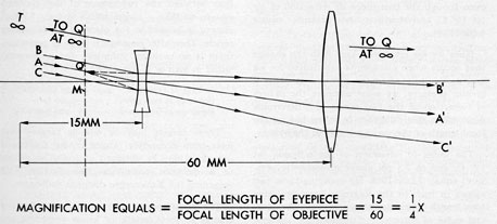
c. Periscope. The magnifying power of a
periscope is simply the combined product of
the powers of all of the component telescopes
of the system, remembering that the power
of any reversed telescope (that is, one with its
short focal length lens toward the incident
light) is the reciprocal of its normal power.
It should be noted that each of the main telescopes in the Type II periscope employs an
eyepiece system consisting of an eye lens and a
collective lens, and in this case the power of
the telescope must be determined by using the
equivalent focal length of the eyepiece
system and the focal length of the objective
lens. See Section 4U9-b, for the method of
determining equivalent focal length of a system
comprising two lens. In the Type II periscope,
the light rays emerge from the head prism
to meet the following telescopic systems in turn.
Type II Periscope
Low
High
Galilean telescope
1/4 X
Out
Upper auxiliary telescope
1 X
1 X
Lower auxiliary telescope
1 X
1 X
Upper main telescope
1/4.7 X
1/4.7 X
Lower main telescope
28 X
28 X
PERISCOPE (combined product)
1.5 X
6 X
A periscope in which it is possible to change
from one power to another is called a bifocal
or bipower instrument.
4U3. Field of view. The true field of view of any
instrument is the angle between the extreme
edges of the field in which the object lies. The
apparent field of view is the angular field covered
by the eyepiece of the instrument. In the Type
II periscope, the apparent field equals 48 degrees.
As indicated in paragraphs a and b the relation
between these two fields and magnifying power
of the instrument is as follows:
True field of view = Apparent field of view/ Magnifying power
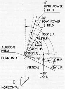
a. High power. With the periscope in
high power, the true field of view equals 48 degrees/6
equals 8 degrees, or 4 degrees on either side of the centerline
of sight. The centerline of sight may be elevated
or depressed as noted in Section 4U6, and shown
in Figure 4-45.
b. Low power. With the periscope in low
power, the true field of view equals 48 degrees/1.5
equals 32 degrees, or 16 degrees on either side of the centerline
of sight. See Figure 4-45 Section 4U6. These
figures, of course, do not include the full 360 degrees
through which the periscope can be trained or
the 74.5 degrees from full elevation to full depression
of the altiscope prism.
c. Narrow 1.414 outer taper section. The
extreme narrowness of the tube sections (second
to ninth inclusive) is the most significant
feature of the Type II periscope. The small outer
diameter (1.414 inches of the outer taper section,
Figure 4-15), which enhances the safety of the
ship by lowering its visibility, is achieved,
without reducing the true field of view, by the
addition of two one-power auxiliary telescopes
in the reduced tube sections of the periscope.
The five lenses thus included bend the rays
toward the optical axis and away from the tube
walls. The addition of five extra lenses is undesirable because of the loss of light and the
deterioration of image quality. However, these
considerations are greatly outweighed by the
decreased wake produced by the small diameter
at the waterline.
4U4. Image brightness. The brightness of the
image seen in the eyepiece of any instrument
depends upon three things: a) the brightness
of the object, b) the transmission efficiency
of the instrument, and c) the relative size of
exit-pupil-of-the-instrument to entrance-pupil-of-observer's eye. Since we can seldom control
209
the brightness of the object, we will consider
the last two factors.
a. Absorption-reflection losses. The
amount of light that is absorbed in passing
through an optical element depends upon the
type of glass, and may vary from 0.06 of 1
percent to 0.10 of 1 percent. For our purposes,
we assume that for each millimeter of glass
path (measured along the axis of the periscope)
0.1 percent of the incident light is absorbed.
Thus, in the Type II periscope at low power
(total glass path = 268 mm) approximately
26.8 percent of the incident light is absorbed.
At high power, the glass path is less because the
Galilean system is out of the field (glass path =
258 mm) and the absorption is only about 25.8
percent. In applying this absorption loss to
the reflection loss in order to determine the
total loss, it is considerably simpler to employ
the transmission which results from the
absorption loss. Thus, at low power, the transmission effected is (100 percent - 26.8 percent
=) 73.2 percent, and at high power, 74.2 percent.
The amount of light that is lost because of
reflection depends upon the difference in index
of refraction of the two optical media which
are bounded by the surface causing the reflection
loss. In most optical systems we find three types
of boundaries, namely, a) air-to-crown glass, b)
air-to-flint glass, and c) silvered glass surfaces.
For our rough calculations of the theoretical
values of reflection loss, we assume that in any
periscope the loss of light at any silvered-glass
surface is about 6 percent; and, on the basis of
the Fresnel theory (see any optics textbook),
we assume that for normal incidence at an
air-crown glass surface, the loss is about 4.1
percent, and at an air-flint glass surface, about
5.6 percent. Again, in applying the above figures
to those resulting from absorption in the glass,
we employ the transmission (100 percent minus
reflection loss in percent).
Since the Type II periscope has (low power)
20 air-crown surfaces, 16 air-flint surfaces, and
2 silvered glass surfaces, the transmission that
would result if the only losses were due to
reflection at the various surfaces is found as
follows:
Transmission =
(1,000 - 0.041)20 X
(1.000 - 0.056)16 X
(0.94)2
This means that 0.959 must be multiplied by
itself twenty times; 0.944 is to be multiplied
by itself sixteen times; 0.94 is to be squared,
and then the combined product of these results
is to be found. In the above case, the result is
found (by use of logarithms) to be 0.1522, or
15.22 percent. This value multiplied by that
for transmission-after-absorption-losses (= 73.2
percent in low power) gives a result of 0.1114,
or 11.14 percent of the incident light that finally
succeeds in getting through the Type II periscope. Thus, we see that the transmission
efficiency of the Type II is only about 11 percent,
about 89 percent of the incident light is lost
when the optical elements have not been coated.
The following table is a comparison of theoretically and actually measured values for glass
that has not been coated, and also the values
for glass that has been coated with a magnesium
fluoride evaporated film. This film is only a few
millionths-inch in thickness on each glass surface, hence, does not appreciably affect the
refraction of the light rays.
Transmission of Incident Light
Low Power
High Power
Uncoated optics (theoretical)
11.1%
14.2%
Uncoated optics (measured) *
14.7%
17.0%
COATED OPTICS (measured) *
33.9%
43.9%
* The actual measurements of transmission were observed by several trained technicians using a Lummber-Brodhun type photometer, and then averaged to provide
the above figure.
b. Effect of papillary size. The amount
of light that can enter an optical instrument
depends upon the area of the entrance pupil
which is proportional to the square of the
diameter of the pupil. Neglecting the losses in
the system, caused by reflection and absorption,
the amount of light that can leave the instrument
is proportional to the square of the diameter of
the exit pupil.
It is apparent that four times as much light
can pass through an exit pupil 6 mm in diameter
as through an exit pupil 3 mm in diameter.
However, the brightness of the image depends
also upon the area of the entrance pupil of the
observer's eye.
The smaller of these two factors is the limiting
factor. If the exit pupil of the instrument is
210
smaller than the pupil of the observer's eye,
the instrument has not been well designed and
it is difficult to hold the eye in position to see
the image and a bright field.
The pupil of the human eye varies in diameter with the brightness of the light entering
the eye, carrying from about 2 mm, in bright
light to about 8 mm in dim light. When the
pupil is fully open, the spherical and chromatic
aberrations inherent in the eye's optical system
cause a falling off in image sharpness. When
the pupil is fully stopped down, the reduced
resolving power of the ocular systems causes a
blurring of the image. Consequently, the ideal
diameter of the eye pupil is somewhere between
these two extremes. Actual measurements have
shown that it is about 4 to 5 mm. It should
be noted that the exit pupil of the Type II
periscope is just 4 mm in both high and low
powers.
c. Relation between central and oblique
brightness. Upon entering the periscope, light
rays from object points on or near the optical
axis travel in lines approximately parallel to
the axis in passing from one component telescope
to the next. Of course, inside each component
telescope these rays converge toward and then
diverge from their respective image points.
On the other hand, light rays from object
points lying near the edges of the field upon
entering the periscope, travel between telescopes
in cylindrical bundles that are not parallel to
the optical axis. And inside each component
telescope these oblique bundles converge toward
and then diverge from their respective image
points. Since the objective lens of the lower main
telescope is well removed from the objective
lens of the upper main telescope, it is apparent
that a sizable departure of any bundle from
parallelism to the axis causes all or part of that
bundle to strike the tube walls and be absorbed.
Thus, the brightness of the image at the margins
of the eyepiece field is always less than the
brightness of the image at the center of the
field. However, the human eye is not too critical
in this matter and if the marginal or oblique
brightness is at least half the central brightness,
it is accepted by the observer as uniform
brightness.
4U5. Orientation of image. Since the two reflecting prisms (head and eyepiece) are arranged
periscopically, that is, the optical axes of both
always lie in the same plane, any change in
orientation of image produced by the head prism
is exactly compensated for by the eyepiece
prism, furnishing a final image that is completely erect. Since, in high power, there is an
even number of inverting telescopes in the
periscope, the final image must be completely
erect. In low power, one telescopic system is
added but this is a Galilean type telescope
which produces an erect image. Therefore, in
all cases, an erect image is seen by the observer.
4U6. Head prism. The letters HA which are
included in the design designation of the Type II
periscope, indicate that the head prism may be
elevated to a high angle, and the periscope is so
designed that the head prism is able to move the
line of sight through a total angle of 84.5 degrees,
that is, from -10 degrees (below horizontal) to +74.5 degrees
(above horizontal). The limits of the field of
view in both powers are shown in the following
table, and Figure 4-45 shows the low-power and
high-power fields of view at maximum elevation
of the prism tilt.
Type II Periscope
Low Power
High Power
Line of sight elevated to +74.5 degrees
Upper limit of field
+90.5 deg.
+78.5 deg.
Lower limit of field
+58.5 deg.
+70.5 deg.
Line of sight depressed to -10 deg.
Upper limit of field
+6 deg.
-6 deg.
Lower limit of field
-26 deg.
-14 deg.
4U7. Target ranging devices.a. Telemeter. Each
large division of a telemeter lens corresponds
to an angle of 1 degree at high power, and 4 degrees at low
power. Each subdivision corresponds to an
angle of 15 minutes at high power, and 1 degree at
low power.
If the angle subtended by the extremities of a
target at the observer (angular size) and the
linear size of the target are known, the range
can be computed.
Since the telemeter is calibrated in degrees
of true field, it provides a means of measuring
the angular size of a target. The space between
successive degree calibrations for high or low
power on the telemeter is equal to f X tan 1 deg,
where f is the focal length of the lens or optical
system forming the image on the telemeter in
211
Figure 4-45. Head prism-elevation and depression
limits.
high or low power as the case may be. Thus the
telemeter can be used as a rangefinder. The
waterline masthead height is independent of
the bearing of the target. Since this height
is known, it is used in finding the range; the
length of the ship is used because its angular
size varies with the ship's bearing. If the range
is determined according to masthead height, a
range determination based on the ship's length
is different unless the course of the target is
perpendicular to the line of sight of the observer.
If two range determinations, one based on height
and one on length, are made, the ratio of the two
is a measure of the course angle. While a telemeter can be used to make range and course angle
determinations as just described, it is not
satisfactory for such determinations because of
the great difficulty in taking a reading from the
telemeter at both extremities of the target when
the observer's ship is not stationary.
b. Stadimeter. The built-in split objective
lens stadimeter overcomes the telemeter lens
difficulty. The angular size of the target is
measured by forming a double image so that
the waterline of one image is coincident with the
masthead of the other image of the same target.
Splitting the image is accomplished by moving
one half of the split objective lens against
the other half until the waterline of one image
and the masthead of the other coincide. By
means of appropriate mechanisms, the movement of one objective half relative to the other
half is translated to a pair of scale dials such
that if the target height is read on one scale
dial, the range is read approximately opposite
the other scale dial. In a similar manner, scale
dials are provided from which the course angle
can be read. While the correct procedure for
taking range and course angle is treated comprehensively in Section 4J13, the principles
involved in the measurement of the angular
size of the target and the subsequent translation
to the stadimeter scale dials are as follows.
For convenience the light image is considered
as being at the center of the field.
1. When the objective halves are in position
so that the split objective lens functions as a
single whole lens, the inter-objective pupil,
that is, the cylindrical bundle parallel to the
optical axis of the periscope, is converged in a
point lying on the optical axis of the lower
objective (and periscope) in the back focal
plane of the lower objective lens.
2. When the halves are moved as shown in
Figure 4-46, the optical axis of each half is
displaced from the periscope axis an amount
equal to the movement of each half. However,
the axis of each half remains parallel to the
periscope axis. The back focal plane of each half
of the objective lens remains in the same plane
as before splitting.
3. Each half now picks up a lesser part of
the inter-objective pupil than it did before
splitting. However, the part picked up by any
half is focused to a point lying on the axis-of
that half and in the back focal plane.
4. Consequently each lens half forms an
image, removed from the center of the field
by a distance equal to the movement of that
objective half.
5. If each half, on moving, causes the center
of the image it forms to move a given amount,
212
Figure 4-46. Lower (split) objective lens ray diagram.
it causes the entire image it forms to move the
same amount.
6. If the split objective lens is normal, or
unsplit, it forms a single image of the target.
The halves, on being moved to different positions, each form a complete image of the target,
displaced by an amount equal to the movement
of that half from the original position of the
target image formed by the unsplit objective
lens.
7. Therefore, it is obvious that if a target
image is split so that the waterline of one image coincides with the masthead d the other
image, the sum of the movements of the objective
halves in opposite directions is equal to the actual
linear height of the target image, that is, waterline to masthead height.
8. If the linear height of the target is known
and the equivalent focal length of the entire
optical system forming the image is known,
the angular height of the image can be computed. That is, for any particular movement
of the objective halves necessary to Inform the
waterline and masthead split-images there is a
corresponding angular height of target.
9. By means of a cam and appropriate
mechanism, the movement of the objective
halves is transmitted in the correct ratio to a
set of scale dials similar to a circular slide rule.
For a certain position of the lens halves, the
values approximately opposite each other on
the height and range scale dials are graduated in
the ratio of target distance to angular height
of the image. Therefore, with the scales in the
same position, the value on the height scale
dials corresponding to the height of the target
lies opposite the target's range on the range
scale dial.
10. Since the oblique pupils are smaller in
cross section than the central pupil, as shown in
Figure 4-46, beyond a certain angle the oblique
pupils fall on only one of the objective halves.
Consequently, when the lower objective lens is
split, no double image appears for that portion
of the field. This accounts for the fact that
splitting does not occur all over the field.
The chief advantages of the stadimeter over
the telemeter are: a) the separation of the
two images, at any stage of the separation, is
independent of any movement of the observer's
ship; b) range angle and course angle are
available directly from scale dials for quick
reading without computation.
4U8. Optical maintenance.a. Arrangement of
optical elements (Figure 4-47, page 54).
1. The Galilean telescope is part of periscope's
optical system only in low power. In high power
both lenses are swung out of the field.
2. Placed in image plane of upper auxiliary
telescope. It is placed in the first real image
plane of the periscope, so that the graduations
appear to vibrate in unison with the image
and observation is easier.
3. It should be noted that the equivalent
focal length of the Ramsden eyepiece system
in the 1.414 periscope just equals the EFL of
the upper eyepiece lens of the Type III periscope.
This establishes the necessary data for machining
the cam grooves that actuate the split objective
lens, and permits the same stadimeter mechanism to be used in both designs.
4. The objective lens of the lower telescope
is split so that the two halves may be shifted
in plane normal to the optical axis to produce
a double image for use in the stadimeter.
5. A total reflection prism which has a
curvature ground on entrance and exit faces
may be called a dioptric prism (that is, a
prism with refracting power), or a double-convex right-angle prism. It serves two functions, namely: it deviates the optical axis from a
vertical to a horizontal direction, and it produces
convergence in the ray bundles that are diverging
from points in the image plane just ahead of the
dioptric prism. In this latter function, it acts as a
collective or field lens for the special eyepiece
system of the Periscope-Ramsden eyepiece.
6. The fixed polaroid must be aligned with
index marks on mount.
b. Ray tracing optical diagram (Figure
4-47, page 54).
214
c. Tracing rays. A ray-tracing optical diagram of any instrument is an abundant source
of information regarding the location and action
of the optical elements in the instrument, if
we are aware of the following four simple rules:
1. Any ray passing through the optical center
of a lens continues in the same direction, that is,
there is no bending by the lens.
2. Any cylindrical bundle of rays entering
a lens is converged to a point in the secondary
focal plane of the lens, not necessarily on the
optical axis.
3. Any cone-shaped bundle of rays diverging
from a point in the primary focal plane of a
lens is converged to a cylindrical bundle.
4. The image of any object-point is the intersection, after passing through the lens, of all
the usable rays from the object point.
These rules apply particularly to positive,
or converging, lenses. By substituting converging
for diverging and vice versa in the above four
rules, they apply specifically to negative, or
diverging, lenses.
5. Thus, referring to the ray tracing as shown
in Figure 4-47, page 54, and to the table in Section
4U2-b we trace various ray bundles through the
Type II submarine periscope by noting their
behavior when passing through the various
optical elements of the instrument:
a) Since the object is at infinity (or practically
so), all the rays from any one point of the object
arrive at the head window in a cylindrical
bundle.
b) Since the head window is planes-parallel,
it does not affect the direction of the ray bundles
or the parallelism of rays in any one bundle.
c) Since the head prism has plane faces
(entrance, reflecting, and exit), it produces
no convergence or divergence in the cylindrical
bundles. The head prism, however, does deviate
the line of sight so that it travels along the
optical axis down the periscope tube.
d) Upper auxiliary telescope. If the Type
II is in high power (see Section 4U8-c-17 for
ray tracing in low power) the Galilean telescope
is swung out of the field, and the cylindrical
bundles next meet the eyepiece of the upper
auxiliary telescope, which lens converges each
bundle to a point in its back focal plane.
e) If the periscope is in proper adjustment,
the plane surface (containing the scale) of the
telemeter lens also lies in this image plane.
Thus, the target image is superimposed on the
telemeter lens, and the rays continue on down
the tube as though they originated at image
points in the plane of the telemeter lens. By
virtue of the fact that these ray bundles are
diverging from the plane surface of the telemeter
lens, that lens has practically no converging
effect on the bundles. It does perform, however, a
collective action by deviating the direction of
each entire bundle. It produces zero deviation
in the one bundle which meets the lens at the
optical axis; but it produces its maximum
deviation in those bundles which meet it
farthest from the optical axis. In other words,
because of its unique position in the system
(that is, in an image plane), this telemeter
lens acts like a thin prism but not like a lens.
f) The objective lens of the upper auxiliary
telescope is placed just one focal length from
the telemeter, so that the ray bundles diverging
from that image plane are converged by it to
form cylindrical bundles that travel down the
tube until they meet the next lens.
g) Lower auxiliary telescope. The objective
lens of the lower auxiliary telescope receives the
cylindrical ray bundles and converges them to
converging bundles with vertices in the back
focal plane of the objective, where the rays, in
each bundle cross this plane at a point, and
then diverge toward:
h) The eyepiece (lens) of the lower auxiliary
telescope, which converges the bundles into
cylinders, since the rays had previously intersected in the front focal plane of the eyepiece.
Thus, as we expect, the lower auxiliary telescope
receives cylindrical bundles of rays and after
inversion, sends them on down the tube as
cylindrical bundles of rays toward the next
optical element.
i) Upper main telescope. The cylindrical
bundles of rays meet the eye lens of the eyepiece
system of the upper main telescope and are
converged toward image points in the back
focal plane of this lens.
215
j) Before the converging bundles reach this
plane, however, they are intercepted by another
converging lens, the collective of the upper
main eyepiece. The collective causes the bundles
to converge still more, so that the rays in each
bundle are caused to intersect sooner than they
otherwise would, and the image plane is just
below the collective lens. From these intersections (image points), the rays diverge until
they meet the next lens in the system:
k) The objective lens of the upper main
telescope receives the ray bundles which are
diverging from the plane above (which is the
front focal plane of the objective) and transforms
them into cylindrical bundles that travel down
the tube to the next telescopic system.
1) Lower main telescope. The objective
lens of the lower main telescope (assume the
two halves are not displaced but form a circle)
receives cylindrical bundles and converges them
to image points in its back focal plane, which is
also the front focal plane of the lower eyepiece
system, since this is a telescope.
m) The rays diverging from this image plane
are converged by the dioptric prism, which
acts as a collective lens for the lower eyepiece.
Since the image plane is closer to the collective
than its own focal plane, the dioptric prism is
unable to converge the various bundles enough
to form cylindrical bundles, hence the ray
bundles enter the next lens:
n) The eye lens of the lower eyepiece system,
with a slight divergence, and the converging
power of the eye lens (that is, the reciprocal
of its focal length) is just enough to transform
the ray bundles to cylindrical bundles.
o) Cylindrical bundles. The cylindrical
bundles pass next through the eyepiece (gas-sealing) window, which is plano-parallel, and
hence are neither deviated, converged, nor
diverged.
p) Rayfilters and polaroids. The rayfilters
and polaroids are also plano-parallel and do
not affect the vergence or the deviation of the
ray bundles, so that the observer's eye finally
receives cylindrical bundles if his eye is normal.
If the observer's eye requires, for example, a
-1.5 diopter setting of the eyepiece unit, he
still receives a sharp image on his retina with
his eye relaxed. Such a setting would merely
indicate that the observer's eye at rest saw
most clearly those objects (or images) which
were 2/3 of a meter distant from his eye.
q) Galilean telescope. When the Type II
periscope is in low power, the reversed Galilean
telescope is included in the system, following
the head prism and preceding the eyepiece
of the upper auxiliary telescope. Since the
Galilean system is a telescope, it transmits
cylindrical bundles if it receives cylindrical
bundles. The action of a reversed Galilean
telescope, however, may not be obvious, and its
formation of images is discussed in the following
drawings:
6. The rays shown in Figure 4-48 are parallel
to each other (although not parallel to the
optical axis) because they are traveling to
the right from a single point (Q) of the infinitely
distant object. This object point is not shown
in the drawing.
The dashed line M to the left of the negative
lens represents the secondary focal plane
of the above lens, and this, of course, is the
plane in which are imaged all infinitely distant
Figure 4-48. Galilean telescope system diagram.
216
objects. The-ray (A) passes through the optical
center of the lens and, therefore, is not deviated
by the lens. It is shown as ray (A') after passing
through the lens. Furthermore, the point (Q')
where the ray (A) passes through the image plane
is the point image of the distant object point
(Q). The other rays, (B) and (C), are each bent
toward the thick part of the lens and, therefore,
rays (B') and (C') seem to be traveling to
the right from the image-point (Q'). This
image, of course, is virtual, the ray bundle
containing rays (A'), (B'), and (C') is diverging
exactly the same amount as though these rays
had actually originated at the point (Q').
If a positive lens, as shown in Figure 4-49,
is placed to the right of the above negative
lens so that its primary focal plane coincides
with the image plane shown, all points in this
plane are imaged by the positive lens at infinity.
This, then, is a simple telescope; the secondary
focal plane of the objective (negative lens in
this case, since it is first to receive the rays)
coincides with the primary focal plane of the
eyepiece (positive lens, since this is the one
nearest the observer's eye). Since one of the
lenses is negative, the image is neither inverted
nor reversed, and the system is called a Galilean
telescope. The reader should refer to the four
rules listed in Section 4U8-c and study their
application in Figure 4-49.
The Type II, Type III, and Type IV periscopes have a divergent meniscus optical glass
element cemented to the equi-concave element
of the Galilean eyepiece lens to correct for
spherical and chromatic aberration.
d. Method of removing parallax caused -by
gas pressure. If the image seen through an
optical instrument is not sufficiently sharp,
the system is said to be out of focus. If the image
is sharply defined, however, it does not follow
that the exact separation of the various lens
elements has been established perfectly, for
the human eye accommodates easily to slight
divergence or convergence of the emerging
ray bundles.
If the instrument carries one or more reticles,
each reticle can be placed in its proper image
plane with near perfection by means of parallax
focusing. Since the Type II submarine periscope
does have a reticle (the telemeter lens), the
setting of this plane exactly in the first real
image plane of the periscope is the problem
we must solve with a great deal of care. When
this is accomplished, the periscope is said to
have no parallax.
Ordinarily this is a relatively simple matter
inasmuch as parallax is detected readily by
looking into the system and shifting the eye
slightly (in a plane normal to the optical axis).
If there is no parallax, there is no apparent movement of the image relative to the reticle, and
if there is an apparent movement of image
relative to the reticle, the image seems to shift
Figure 4-49. Galilean telescope system diagram.
217
in the same direction as the eye or in the
opposite direction. When the shift of the image
(relative to the reticle) is with the eye, we know
that the image is farther from the eye than the
reticle. When the shift of the image is against
the eye, the image is closer than the reticle.
(In the case of a submarine periscope, such as
the Type II, which has a split lower-main telescope objective lens, the above method
is not practicable; consequently, a good auxiliary
telescope must be adjusted to the observer's eye
and then used as follows: For the coarse adjustment, change the diopter setting of the periscope
eyepiece and note whether the target image and
telemeter reticle both come in and go out of
focus simultaneously. For the fine adjustment,
vary the diopter setting of the auxiliary telescope eyepiece and look for the above
condition.)
Achieving the condition of no parallax in
the Type II periscope is complicated by the
fact that the proper separation of the various
lenses is established while the optical system is
surrounded by air (at normal atmospheric
pressure), while the periscope is to be used with
the optical system surrounded by dry nitrogen
at 7.5 psi above atmospheric pressure. Now
the index of refraction of the various kinds of
glass comprising the optical system of the Type
II may be used to calculate the focal length
(or refracting power) of each of the lenses, and
if we assume that the index of refraction of air
is 1.00000000 no appreciable error is obtained,
even though the true index of refraction of air
(at 15 degrees C, and at atmospheric pressure) equals
1.00027734.
Since we are concerned herewith the change
that occurs when nitrogen is substituted for air
and particularly when the nitrogen is under a
greater pressure, we must compare the indices
of refraction of the two media and determine
what effect this difference in index has on the
focal length of the various lenses in the system.
The index of refraction of the nitrogen (at
15 degrees C, and at 7.5 psi above atmospheric pressure) equals 1.00041968. By applying these two
values in turn to the formulas for calculating
focal length (when curvatures, index of the glass,
and index of surrounding medium are known),
it may be calculated that when a lens is surrounded
by nitrogen under the above conditions,
it has a focal length (EFL) which is 1.00038
times the focal length of the same lens in air
under normal conditions.
This means that if we remove parallax with
the system in air and then gas the periscope to
plus 7.5 psi, the telemeter reticle no longer lies
in the image plane of the upper-auxiliary telescope eyepiece of the Type II periscope. It
is necessary, in fact, before gassing the instrument, to increase the separation between the reticle and the preceding image-forming lens
(in high power) by the factor 1.00038. This may
be done by mechanical measurements; however,
a much simpler method is to perform this shift
optically, as follows:
If we use a target that is not infinity (when
the system is in air) but is just 1,200 feet distant,
the image formed by the upper-auxiliary telescope eyepiece falls slightly more than one
focal length behind the eyepiece; in fact, it
is just 1.00038 focal lengths behind the lens.
Thus, when the parallax has been removed
(high power) for a target 1,200 feet distant
while the system is in air, after gassing the
periscope, all targets that are infinitely distant
are imaged exactly on the telemeter reticle;
that is, there is no parallax.
After establishing the above separation between the telemeter reticle and the preceding
image-forming lens, swing the Galilean system
into the field (low power) and adjust the separation between the two lenses of the Galilean
system so that a target which is only 35 feet
distant is imaged in the plane of the telemeter
reticle. Then after gassing the Type II periscope,
there is no parallax (infinitely distant targets)
either in high or in low power.
Type II Periscope
Target Distance
Periscope in high power
1,200 feet
Periscope in low power
35 feet
These targets may be outside targets that
have been accurately ranged or, for shipboard
use, they may be obtained optically by means
of a distance collimator. See Section 4V8
regarding the Kollmorgen distance collimator.
The above adjustments compensate for the
change in focal length of lenses preceding the
telemeter. For lenses that follow the telemeter,
218
set the periscope eyepiece at -3/4 diopters
before gassing and return the eyepiece to zero
diopter setting after gassing.
It is important to realize that the proper
pressure for the nitrogen is from 5 to 7.5 psi.
If the pressure is outside these limits there
definitely is parallax in the instrument.
4U9. Glossary of optical terms.
a. Single thin lens.
1. Lens: any piece of glass or other optical
medium that is bounded by two curved surfaces, usually spherical.
2. Center of curvature: the center of the
sphere of which the lens face is a part.
3. Optical axis: the straight line connecting
the centers of curvature of the two faces.
4. Thin lens: any lens thin enough that
the primary and secondary nodal planes may
be considered to coincide with each other and
with the geometrical center plane of the lens
itself.
5. Ray bundles:
a) Diverging bundles: all the rays that
diverge from a single point of the object, or
image, until they meet a refracting surface.
b) Cylindrical bundles: same as the diverging bundles except that the object point is so
distant that only those rays that are parallel
to each other succeed in getting into the lens.
c) Converging bundles: rays from a single
object point that have been converged by a
positive lens.
d) Paraxial bundles: ray bundles originating
from an object point that lies on or near the
optical axis of the lens.
e) Oblique bundles: originating from an
object point that lies off the axis, near the
margin of the field.
6. Object point: that point of the object
which is under consideration.
7. Image point: that point of the image
which corresponds to the object point under
consideration; both object and image consist
of an infinite number of points.
8. Object plane: that plane in which the
object point lies which is normal (perpendicular)
to the optical axis.
9. Image plane: plane normal to the axis,
in which the image point lies.
10. Object distance: distance along the
axis from an object plane to the center plane
of a lens.
11. Image distance: distance along the axis
from the image plane to the center plane of a
lens.
12. Secondary focal plane: plane in which
the image is formed when an object is at infinity.
13. Primary focal plane: plane in which to
place the object in order to produce an image
at infinity.
14. Focal point, primary or secondary:
intersection of axis with appropriate focal plane.
15. Focal length: distance between focal
plane and center plane of the lens.
16. Conjugate planes: planes so spaced
that if the object lies in one, the image lies
in the other. Thus, infinity and the secondary
focal plane are conjugate. If the object distance
is known in terms of the focal length of the
lens instead of in inches or millimeters, it is
quite easy to determine the image distance by
the formula: if object distance equals n focal
lengths, the image distance equals n/(n - 1)
focal lengths.
17. Prism: any piece of glass or other
optical medium that is bounded by two or
more plane surfaces. Since ordinary prism faces
have no curvature, the prism has no refracting
power. The prisms does, however, produce a
deviation in the incident bundles of rays.
18. Prism diopter: unit of deviation produced by a thin prism. If a prism produces a
deviation of one centimeter in one meter of
travel, it is said to have a power of one prism
diopter, which is equivalent to an angle of ten
mils.
19. Dioptric image: Newtonian terminology
denoting any image formed by refraction, that
is, by lenses.
219
20. Catoptric image: Newtonian terminology denoting any image formed by reflection,
that is, by a mirror or prism.
21. Dioptric prism, or catoptric lens:
derived name for the eyepiece prism of the
1.414 periscope, indicating that this collective
prism both deviates the incident bundles and
contributes convergence to these bundles.
22. Nodal planes: See Section 4U9, paragraph b-5.
b. System of two thin lenses. A system
of two thin lenses may be considered as a single
thin lens if the following three quantities are
first calculated:
1. Equivalent focal length: the focal length
of an imaginary thin lens that is equivalent
to the focal length of the combination of lenses.
2. Back focal distance: distance from back
surface of second lens to the secondary focal
plane of the system.
3. Front focal distance: distance from
front surface of the first lens to the primary
focal plane of the system.
Back focal distance =
((f1 X f2) - (S X f2)) / (f1+f2-S)
Front focal distance =
((f1 X f2) - (S X f1)) / (f1+f2-S)
f1 and f2 denote the focal lengths of the first
and second positive lenses respectively; and
S is the separation between them in the same
units of linear measure.
The rules for locating on a simple optical
diagram, the positions of the front focal point
(f), the back focal point (f'), and the primary
and secondary nodal planes (N and N' respectively) of the above system are indicated below
for the case where each quantity is positive.
If any quantity works out toy be negative in
value, take measurements in a direction opposite
to that indicated.
FFD: measure from the surface of the first lens
to the left a distance equal to the value found.
BFD: measure from the surface of the second
lens to the right a distance equal to value
calculated.
EFL: from the front focal point (F) measure
to the right to locate the primary nodal plane
(N), a distance equal to value found for EFL;
from the back focal point (F') measure to the
left to locate the secondary nodal plane (N'), a
distance equal to the value found for EFL.
Thus, the equivalent focal length of any combination of lenses is always the distance from
either of the focal points of the system to the
corresponding nodal plane.
5. Nodal planes: the primary nodal plane
(N) of any system may be considered to be
the plane of arrival for all rays entering the
system, just as the secondary nodal plane (N')
is said to be the plane of departure for all rays
leaving the system. The object distance in
the case of a system is always measured from
the object plane to the N-plane; and the image
distance is always measured from the N'-plane
to the image plane.
6. Separation: when the distance between
two lenses comprising a system has certain
special values, optical systems with special
characteristics are formed:
a) When the separation equals the sum of
the two focal lengths, the system is a telescope.
b) When the two focal lengths are equal and
the separation is equal to 2/3 of either, the
system becomes a Ramsden eyepiece. This
system is a form that has been modified to
improve the color correction and is the type
used in most telescopes and in main telescopic
systems of periscopes.
c) When the focal length of the first lens
equals three times the focal length of the second
lens, and the separation equals 1/2 the sum of
the two focal lengths, the system becomes known
as a Huyghens eyepiece, which is commonly
used in microscopes. The Huyghens ocular
does not take a graduated reticle nearly so well
as does the Ramsden eyepiece.
d) When the separation between the first and
second lenses of any eyepiece equals the average
of the two focal lengths, the system is well
corrected for chromatic aberration.
220
c. Optical instrument.
1. Inverting telescope: two positive lenses
separated by a distance equal to the sum of their
focal lengths. See Section 4U2, for magnifying
power.
2. Galilean telescope: one positive lens
and one negative lens separated by a distance
equal to the algebraic sum (arithmetic: difference) of their lengths.
3. Periscope: two main telescope systems
aligned so that one optical axis coincides
with the other, and placed with the two objective lenses facing each other. This arrangement
satisfies the mechanical limitation of great
length compared to the diameter of the instrument. It consists of a tube containing the above
and provided at each end with reflecting surfaces, either mirrors or reflecting prisms, inclined at 45 degrees to the axis of the tube, so that an
observer looking into one mirror (generally
looking through an eyepiece) can see the
objects reflected by the other mirror.
4. Magnifying power of any optical instrument:
Magnifying power = (Size of image seen through instrument) /
(Size of image seen by eye alone)
5. Magnifying power of simple telescope:
defined three ways:
a) MP =
(Focal length of objective) /
(Focal length of eyepiece*)
b) MP =
(Diameter of entrance pupil of instrument) /
(Diameter of exit pupil of instrument)
c) MP = Apparent field of view (object nearest eye) / True field of view (eyepiece nearest eye)
6. Magnifying a power of periscope: the
power of a periscope is the product of the
magnifying powers of all the component telescope systems. Reversed telescopes have powers
that are reciprocal to their normal power;
in other words, the Galilean telescope has a
* EFL if eyepiece is a system.
magnifying power equal to 1/4 and the upper main
telescope has a power equal to 1/4.7.
d. Ray tracing considerations. It may
be helpful to consider the behavior of a bundle
of light rays in traversing an optical instrument.
From each point of the object, light rays
traveling in straight lines are radiating in all
directions. We are interested, of course, only
in those rays from a given object point that
are directed in order to enter the first lens
of our system. If this system is a telescope, the
object is at infinity, or at a great distance,
and the only bundles that enter the objective
are those in which all rays are parallel to each
other but not necessarily parallel to the optical
axis of the instrument.
Upon passing through the objective of the
telescope, these various cylindrical bundles
are converged to their respective image points
in the back focal plane of the objective lens;
from these points they cross over and diverge
toward the eyepiece lens. The eyepiece lens
causes the diverging bundles to converge (since
each bundle is coming from a single point in
the front focal plane of the eyepiece) just
enough to form cylindrical bundles again. Thus,
the telescope forms at infinity an image of
some object that is also at infinity, this image
being magnified or minified in size and inverted
or left erect, depending upon the type of
telescope.
If we trace the rays through the Type II
periscope, we need only consider that each
telescope system in the periscope acts in the
manner outlined above, receiving cylindrical
bundles of rays from each object point (and
there are an infinite number of such points
in every object, however small the object) and
emitting cylindrical bundles toward the next
telescope in the system. It is suggested that the
student form a periscope by suitably placing
two auxiliary telescopes, for example, a 3x
and a 5x. Keeping them coaxial, vary the distance between the two objective lenses to
note the effect on image sharpness and on
image brightness. The only limitation is found
to be the brightness difference between the
center and the margin of the field of view as
seen through the eyepiece of the second telescope.
221
In the Type II periscope, the field of view
of the eyepiece is approximately 48 degrees, which is
the apparent field of view of the periscope
itself. If the center of the field is arbitrarily
defined as that part lying within 11.5 degrees of the
optical axis, the margin is then the rest of the
field lying outside this inner circle of 23 degrees diameter. Those parts of the object lying on or near
the line of sight are of course, imaged near the
center of the field (by the central ray bundles);
while those parts of the object lying off the axis
are imaged (by the oblique ray bundles) in the
margin of the field. Inasmuch as the central
bundles travel down the periscope tube nearly
parallel to the optical axis while going from one
telescope to the next, they reach the observer's
eye practically in their entirety. The oblique
bundles, however, in passing down the periscope,
make a considerable angle with the optical axis
between the telescopes. Thus, if there is a large
distance between the telescope systems, as there
is between the two main telescopes, part of the
oblique bundles are bent toward the tube walls
where they are absorbed by the anti-reflection
threading or by the diaphragm stops and thus
fail to reach the entrance pupil of the observer's
eye. The brightness of the margin of the field,
consequently, is always less than the brightness
of the center.
The design of the periscope is simplified
by the fact that the human eye is not critical
in the matter of comparing central and marginal
brightness. In fact, if the margins are at least
half as bright as the center of the field, the
average observer agrees that the brightness is
uniform throughout. If the marginal brightness
is less than half the central brightness, the
observer complains that the illumination is not
uniform.