3A1. Functions. The main hydraulic system
performs the bulk of the hydraulic work
aboard a submarine. Lines from the central
power source radiate throughout the ship to
convey fluid under pressure for the operation
of a large variety of services. The vent valves
of the main ballast, fuel oil ballast, bow buoyancy
and safety tanks, and the flood valves of
the negative and safety tanks are hydraulically
opened and closed by power from the
main system. It also operates the air induction
valves, the outer doors of the torpedo tubes,
the bow plane rigging gear, the forward windlass-and-capstan,
the echo-ranging and detecting apparatus (sound heads), and the main
engine exhaust valves on earlier classes of
boats. (In some of the latest installations the
main engine exhaust valves are operated by
pneumatic-hydraulic, or air cushion, units.)
In an emergency the main hydraulic system
is also called upon to supply power for the
steering system and for the tilting of the bow
and stern diving planes, although these systems
normally have their own independent
power supply units.
On the latest classes of boats, the periscopes and antenna masts are also hydraulically operated as units of the main hydraulic
system. In earlier classes, they are electrically operated.
3A2. Component parts. In order to perform
these numerous tasks, a variety of valves,
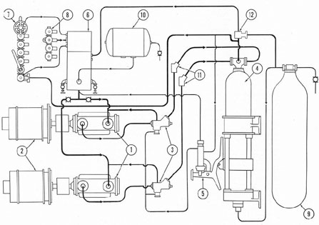
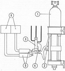
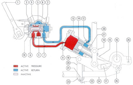
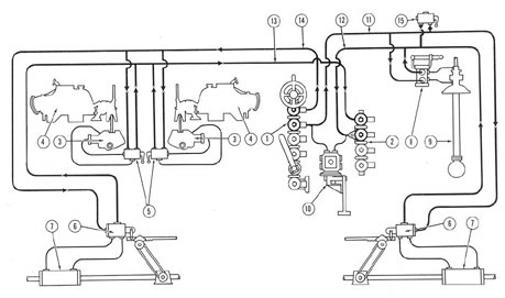
Figure 3-1. Schematic piping diagram of power generating system.
1) IMO pumps; 2) 18-horsepower motors; 3) automatic bypass and non-return valves; 4) accumulator; 5) pilot
valve; 6) main supply tank; 7) main supply manifold; 8) main return manifold; 9) accumulator air flask;
10) back-pressure air, or volume, tank; 11) non-return valves; 12) air-loaded relief valve.
41
actuating cylinders, tanks, and manifolds is
required, as well as the pumps for building up
the required power. The units of the main
hydraulic system fall conveniently into five
groups:
a. Power generating system.
b. Floods and vents.
c. Periscope and radio mast hoists.
d. Forward and after service lines.
e. Emergency systems.
A schematic view of the main hydraulic
system in the submarine may be seen in
Figure 7-1 at the back of the book.
B. POWER GENERATING SYSTEM
3B1. General arrangement. The power generating system consists of a group of units
whose coordinated action provides the hydraulic power necessary for the operation of
the main hydraulic system. It consists of the
following principal parts (see Figure 3-1):
a. The IMO pumps (1) supply hydraulic
power to the system.
b. The main supply tank (6) contains the
oil needed to keep the system filled.
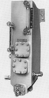
Figure 3-2. Main supply tank.
c. The accumulator (4), as the name implies, accumulates the oil from the pump and
creates pressure oil which is maintained at a
static head for instant use anywhere in the
system.
d. The main supply and return manifolds
(7 and 8) act as distribution and receiving
points for the oil used throughout the system.
e. The pilot valve (5) is a two-port, lap-fitted trunk, cam-operated slide valve, which
directs the flow of oil that causes the automatic bypass valve to open or close.
f. The automatic bypass and nonreturn
valves (3). The automatic bypass valve directs
the flow of pressure oil in response to the
action of the pilot valve. The nonreturn valve
prevents the oil from escaping through the
open automatic bypass.
g. Cut-out valves, serving various purposes throughout the system and nonreturn
valves to permit one-way flow.
h. The back-pressure tank, or volume
tank (10), contains compressed air at a pressure of 10 to 25 pounds per square inch, which
provides the air pressure on top of the oil
in the main supply tank and maintains the entire system full of oil.
i. The accumulator air flask (9) serves as
a volume tank for the accumulator, allowing
the air to pass to and from it when the accumulator is loading or unloading.
3B2. Detailed description. a. Pumps. Power
is developed for the system by means of two
IMO pumps. The power rotor of each pump
is direct-coupled to an 18-horsepower electric
motor which drives it at about 1750 revolutions per minute. The two IMO pumps were
described in Sections 2B1 to 2B3. They may
be operated either singly or both at once, depending upon the volume of oil required by
the system at a given moment. Ordinarily a
single IMO pump is sufficient to supply the
42
required volume of oil. However, when operation of the hydraulic units creates a heavy
enough demand, the driving motor of the second IMO pump is switched on. The switch
can be set on either manual or automatic control.
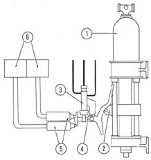
b. The main supply tank. Fluid is supplied to the pumps from the main supply tank
(see Figure 3-2). The shape of this tank varies
in different installations. Its total capacity is
50 gallons, but the normal supply maintained
there is only 35 gallons; the 15-gallon difference is an allowance made for discharge from
the accumulator and thermal expansion of the
oil.
When the system is operating, the fluid
circulates through the power system, returning to the supply tank. However, the fluid will
not remain in the supply tank for any length
of time, but will be strained and again pumped
under pressure to the accumulator and the
manifolds.
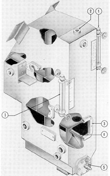
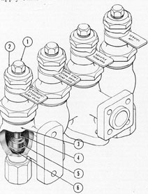
Figure 3-3 shows another view of a main
supply tank with some sections partly cut
away to show the internal structure.
Glass-tube sight gages (1) mounted on
the side of the reservoir give minimum and
maximum readings of the amount of oil in
the tank. A drain line and vale (5) near the
bottom of the tank provide a means for draining water which may have accumulated there.
The back-pressure tank is connected by a
length of pipe to the top of the supply tank
(air inlet [2]), It maintains an air pressure of
10 to 25 pounds per square inch on the oil in
the supply tank. This forms an air cushion
between the top of the tank and the body of
the fluid and maintains the system in a full
condition. An air relief valve set to lift at 48
pounds per square inch prevents the building
up of excessive air pressures in the supply
tank.
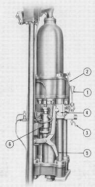
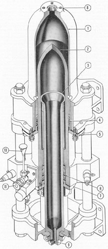
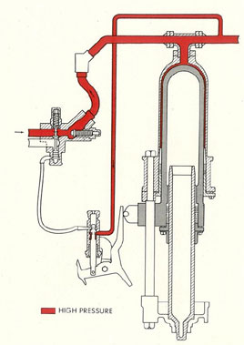
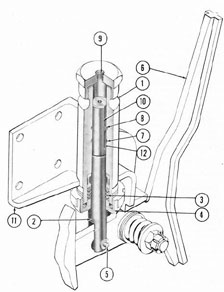
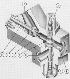
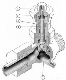
c. Accumulator. ( See Figure 3-4.) 1.
Basic principles of operation. Oil which is
discharged by the IMO pumps is directed to
the accumulator until the required quantity
is obtained. The accumulator receives and
stores fluid under pressure and transmits it
to the system as it is needed. Actually, the
accumulator serves the same purpose as a
storage battery in an electric system which
retains an electrical charge until it is used.
Then the charge must be replaced or the
battery becomes discharged, or exhausted.
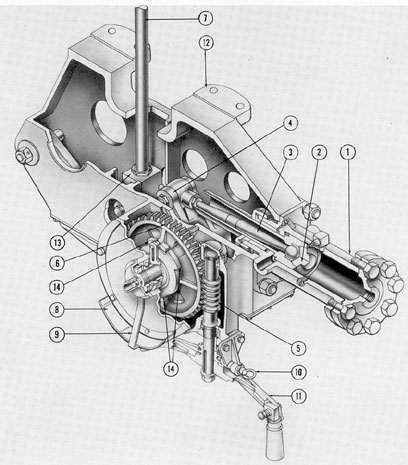
2. Principal parts. The accumulator has
three principal working parts: the oil cylinder,
the air cylinder, and the plunger. The
cutaway view (Figure 3-5) shows the internal
structure of the unit.
The oil cylinder (1) receives oil from the
IMO pumps through the passage (8) at the
top of the cylinder.
Air is admitted into the lower end of the
air cylinder (3) through the inlet (9), from
the accumulator air flask.
Figure 3-3. Cutaway of main supply tank.
1) Gage; 2) air inlet; 3) hand hole for strainer; 4) strainer mounting base; 5) valve.
43
Air pressure is exerted against the inner
surface of the plunger (2) while oil pressure
acts on its outer surface. Therefore, its position
in the accumulator varies in relation to
the differences between the air pressure on
the inner surface and the volume and pressure
of the oil acting on the outer surface.
Leakage past the inner and outer surfaces
of the plunger is prevented by chevron, or C-type
ring packing (4 and 6). These packing
rings nest together and are held in place by
the packing glands (5 and 7). Note that both
the air cylinder and the oil cylinder are
Figure 3-4. Accumulator shown with pilot valve.
1) Oil seal fill; 2) oil cylinder drain; 3) oil seal drain;
4) cam roller; 5) pilot valve operating arm; 6) pilot
valve.
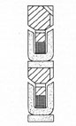
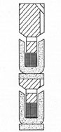
equipped with drain valves. The oil packing
is shown assembled in Figure 3-6. The air
packing is illustrated in Figure 3-7.
A gage connected to the oil line leading
to the accumulator indicates the oil pressure
on the pressure side. The air system is also
Figure 3-5. Cutaway of accumulator.
1) Oil cylinder; 2) plunger; 3) air cylinder; 4) oil
cylinder packing; 5) packing gland; 6) air cylinder
packing; 7) packing gland; 8) oil inlet; 9) air inlet;
10) oil seal fill; 11) oil seal valve.
44
equipped with a gage for indicating the air
pressure in the air side of the accumulator.
In order to prevent leakage from the air side
of the accumulator, an oil seal is provided.
The oil filler connection (10, Figure 3-5)
attached to the plunger supplies oil to a narrow
space between the air cylinder and plunger,
above the packing. Since the packing will not
retain high pressure air, the oil seal is placed
on top of the packing. Therefore the high-pressure air acts against the oil seal instead
Figure 3-6. Accumulator packing (oil).
Figure 3-7. Accumulator packing (air).
of the packing. Oil is poured through a pipe
and funnel in the oil filler until its level
reaches the mid-position of the funnel. The oil
filler pipe is mounted in a trap which catches
water. A stop valve is fitted to the oil filler to
retain the oil seal within the accumulator;
also, a needle-type drain valve (3, Figure 3-4)
is provided to empty the trap and the oil seal
from the air cylinder packing gland.
3. Operation. The oil cylinder and the
air cylinder are stationary. The plunger,
however, can slide up or down inside the oil
cylinder and over the air cylinder. Before the
IMO pumps are started, the accumulator air
flask and the air cylinder are charged with
compressed air to a pressure of 1750 pounds
per square inch from a connection to the high-pressure air system. The cut-out valve for
opening the high pressure service line is
shown at the extreme right of the piping
diagram, Figure 3-1, on the line leading off
from the accumulator air flask (9, Figure 3-1).
When the pumps are stopped, air pressure
holds the plunger at the top of its travel,
ready to receive the charge of pressure oil
from the pumps. Since it is the charge of pressure oil that determines the load conditions
of the oil cylinder, the cylinder will, therefore, be under no-load when the pumps are not
running. In starting the system, it is desirable
but not necessary to maintain the no-load
condition until normal operating speeds have
been attained. Therefore, the hand bypass
valve on the main supply manifold is opened,
and one of the IMO pumps is switched on.
The opened hand bypass valve allows the oil
from the discharge side of the pump to flow
back to the supply tank, relieving the pump of
any load, until it has attained normal operating speed.
The hand bypass valve is then closed,
and the oil from the discharge side of the
pump begins, to fill the oil cylinder in the
accumulator.
When the hand bypass valve is open, the
plunger is held at the top of the cylinder by
air pressure. Therefore, closing the hand bypass valve forces sufficient pressure oil from
the pump into the oil cylinder, on the outer
surface of the plunger, to meet and overcome
the force exerted by the air upon the inside
of the plunger, thus pushing the plunger
down in the oil cylinder. The oil pressure in
the line between the discharge side of the
pump and the accumulator will rise immediately
to a value sufficient to overcome the air
pressure that tends to force the plunger up.
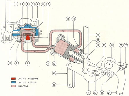
The two operating diagrams, Figures 3-8
and 3-9, illustrate the action which takes
place.
45
Figure 3-8. Accumulator In fully loaded position.
1) Plunger; 2) automatic bypass valve piston; 3) pilot
valve; 4) air chamber; 5) cam roller; 6) pilot valve
operating arm; 7) automatic bypass valve; 8) from
pump; 9) bypass to pump suction; 10) nonreturn valve
spring; 11) nonreturn valve.
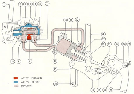
Figure 3-9. Accumulator In unloaded position.
46
The force of 600 to 700 pounds exerted by
this oil upon the outer surface of the plunger
(1, Figure 3-8) will force it to travel downward until it has reached the limit of its
downward stroke, tripping-the pilot valve
operating arm, as shown in Figure 3-8.
The pilot valve (3) which hydraulically
operates the automatic bypass valve will cause
the automatic bypass valve to open when a
column of oil is sent from the pressure side
of the system to the underside of the automatic bypass valve piston (2). The oil coming
from the discharge side of the pump through
the line (8) is now bypassed directly back
through the line (9) to the pump's suction
side. This allows the nonreturn valve (11) to
close, shutting off the line between the pump
and the accumulator so that the pressure oil
in the accumulator will not returns through
the open bypass valve.
In practice, the pump can either be run
continuously or switched off automatically by
the use of a toggle switch as the plunger approaches
the bottom of its stroke. However,
the automatic bypass valve serves as a further
precaution to guarantee that no more pressure
oil will be forced into the accumulator line
after the accumulator is fully charged. In this
condition, the full charge of oil will be
maintained under pressure in the accumulator.
However, this is only theoretically true. In
practice, the accumulator will not remain
fully charged indefinitely, even when no
hydraulic mechanisms are being operated,
since there is always a slight oil leakage at
various points in the system.
If a control valve were opened at some
point in the system, utilizing some of this
stored oil to operate a hydraulic mechanism,
the force exerted by the compressed air at
1750 pounds per square inch upon the inner
surface of the plunger would immediately
cause the plunger to travel upward.
When enough of the oil charge has been
used, the plunger cam roller, as in Figure 3-9,
will trip the pilot valve, closing the automatic
bypass valve, and again directing the oil from
the discharge side of the IMO pump through
the nonreturn valve to the accumulator. The
pressure oil will again begin to charge the
accumulator, forcing the plunger downward.
4. Automatic switches and contact makers. The
cam roller on the plunger actuates
the pilot valve operating arm, which not only
operates the pilot valve, but also at different
intervals throws two electrical contact makers
which switch on the IMO pumps as the
plunger is traveling upward and switch them
off again as the plunger travels downward.
Figure 3-10 shows schematically how the
contact makers, switches, and electrical wiring are arranged. The cam roller (2, Figure
3-10) is shown in a position intermediate between the highest and lowest limits of its
travel. As it moves in either direction from
Figure 3-10. Contact makers for pump controls.
1) Accumulator; 2) cam and cam roller; 3) pilot
valve; 4) pilot valve control arm; 5) contact makers;
6) motor switches.
this intermediate point, it actuates the pilot
valve operating arm, which throws the contact makers (5) connected to the motor
switches (6). The wiring is so arranged between the contact makers and the manual
push-buttons that, when required, either or
both pumps can be automatically switched on
or off by the motion of the cam roller. This
arrangement permits each pump to be used in
turn at continuous service, so that both pumps
will receive equal wear.
5. Explanation of pressure differential.
The oil pressure on top of the plunger varies
47
between 600 and 700 pounds per square inch,
while the air pressure underneath it is maintained
at 1750 pounds per square inch. Since
the air pressure is so much greater than the
oil pressure, the oil, to be able to exert a force
sufficient to overcome that of the air beneath
it, allowing the plunger to travel downward,
must be acting over a greater area than the air.
This is in fact true. The area on the oil
side of the plunger is much larger than the
area on the air side, the ratio between the two
areas, being approximately 3 to 1. Since the
total force exerted by a fluid at a given pressure
is proportional to the area over which it
is exerted (see Section 1B3b), it follows that
an oil pressure of 600 pounds per square inch
exerted on the larger area of the oil side of
the plunger will be sufficient to overcome an
air pressure of 1750 pounds per square inch
exerted against the smaller air side of the
plunger, which is only about one-third as
large as the oil side.
6. Function of the air-loaded relief valve.
In Figure 3-1, an air-loaded relief valve (12)
is seen just beyond the top of the accumulator.
This valve contains a double-ended piston,
one end of which is air-loaded by a small secondary line running from the accumulator air
flask. The other end of the piston is in contact
with the high pressure oil from the oil cylinder in the accumulator.
The ratio between the area of one surface
of the piston and the area of the other surface
is approximately 3 to 1, or about the same as
the ratio between the area of the oil side of
the plunger to the area of the air side.
This ratio will not allow for an oil pressure overload of more than 10 percent. In
other words, if the oil pressure increases to a
value which is more than 10 percent over one-third of the air pressure, the valve piston
will lift, allowing oil to escape from the accumulator back to the return side of the system until the 3:1 ratio between air pressure
Figure 3-11. Main supply manifold.
1) Bypass; 2) service aft; 3) service fore; 4) emergency planes; 5) emergency steering; 6) quick-throw cutout; 7) relief valve; 8) to control manifolds; 9) to pilot valve supply; 10) to gage and vent.
48
and oil pressure is restored. For example, if
the air pressure, because of leakage, fell off to
1500 pounds, the oil pressure to maintain the
correct ratio would be about 500 pounds. If
now the oil pressure were to exceed 550 pounds
per square inch (one-third of the air pressure
plus 10 percent), the valve would lift, allowing the oil to escape from the accumulator
back to the return side of the system.
The valve will function correctly regardless of variations in the value of the air pressure.
This air-loaded type of relief valve is currently installed only on Portsmouth built
boats. It is intended to furnish additional protection since the existing relief valves in the
high pressure side of the system are not adequate to handle an overload when both IMO
pumps are running.
On submarines of Electric Boat Company
design, the line from each IMO pump is provided with its own relief valve, making unnecessary the inclusion of an air-loaded relief
valve in the high pressure side of the system.
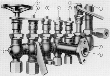
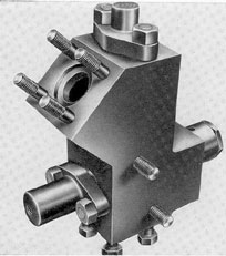
d. The main supply and return manifolds.
1. Hydraulic fluid discharged by the accumulator is conveyed to the main supply manifold
(see Figure 3-11) where its flow is distributed
to the supply lines and also to the control
valve manifolds. The returning fluid flows
through lines to the main return manifolds
which then deliver it back to the oil supply
tank.
The supply manifold consists of a series
of valves combined into a single unit. The
opening or closing of any of the valves either
permits or interrupts the flow of hydraulic
fluid controlled by that valve without
affecting the other valves in the manifold. The
valves are all connected into a common fluid
channel, but distribution of the oil is made
through pipe lines attached to those valves
which supply a group of hydraulic units. The
return manifold is similar in design to the
supply manifold.
2. The main supply manifold has seven
valves, a bypass valve (1, Figure 3-11), four
supply valves (2, 3, 4, and 5, Figure 3-11), a
quick-throw cut-out (6), and a relief valve
(7). The four supply valves are connected to
the forward and after service lines and to the
emergency systems for steering and plane
tilting.
A flanged port (8) connects with the flood
and vent control manifolds. A small opening
under the relief valve at the end of the fluid
channel (9) provides a connection to the pilot
valve. A small opening (10) in the hand bypass valve body provides for a gage and vent
connection. Both the pilot valve and the gage
and vent connections are always open to the
common oil passage in the manifold.
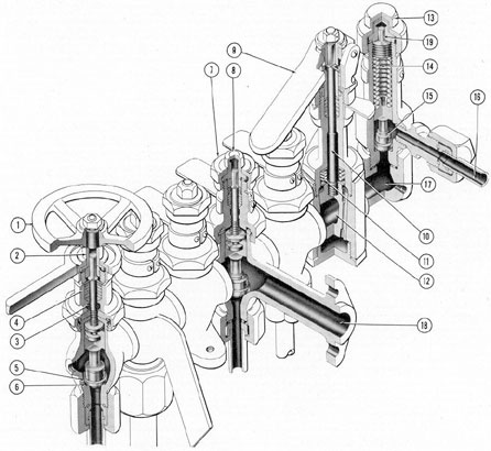
3. The bypass handwheel (1, Figure 3-12)
is attached to the collar (2). The upper end of
the stem (3) is square, to fit into the collar
inside the squared hub of the handwheel (1).
The lower end, passing through the packing
(4), is attached to the short stem which is attached to the disk (5). When the handwheel
is turned to the left, the disk (5) is raised
off its seat, opening a passage between the
central fluid channel and the port at the bottom. At the time the IMO pumps are started,
the bypass is opened so that the oil will flow
freely from the pump back to the supply tank
until the pumps attain their maximum speed.
Then the bypass is closed so that hydraulic
pressure will build up.
4. Starting from left to right in Figure
3-12, the bypass valve appears first. The next
four valves supply hydraulic fluid to:
a) After service line.
b) Forward service line.
c) Emergency bow and stern planes system.
d) Emergency steering system.
The internal mechanism of these valves is
identical with that of the bypass valve. The
valve is operated by a double-ended wrench.
The small end fits over the turn-nut (8) to
rotate the inner mechanism. Before the turn-nut
can be moved, the locking cap (7) must be
backed off slightly with the large end of the
wrench. After each operation, the lock cap
is tightened to prevent accidental turning of
the valve stem.
5. A quick-throw cut-out valve is provided on the supply manifold. This is a
49
tapered plug-type valve. Its method of operation is somewhat different from that of the
disk valves. The plug valve has an elliptical
hole cut through its center. It can be turned
by the lever (9) through the stem (10) so that
the hole is in line with the fluid passage in
the manifold, or turned in the opposite direction, thereby cutting off the flow of oil to
supply valves and manifolds. The valve is
spring-loaded and must be lifted off its seat
by the handle before it can be turned. The
plug valve is provided as a means for rapidly
blanking off the oil lines from the power
group to the rest of the units in the main
hydraulic system.
6. A relief valve of conventional type is
installed on the manifold for relief of excessive pressure. The normal operating oil pressure for the main hydraulic system is 600 to
700 pounds per square inch. The relief valve,
however, is adjusted to open when the pressure reaches 750 pounds per square inch, since pressures in excess of 750 pounds per square inch may cause damage to the equipment. The valve (15) is held on its seat by spring (14) until oil pressure overcomes tension on the spring. When this occurs, the valve is lifted off and passes through port (16) to the supply tank. The tension on the spring is regulated by the
adjusting nut (19). The retaining cap (13) prevents leakage from valve.
7. The main return manifold, illustrated in Figure 3-13, has four valves which are connected to the following lines:
a) After service line.
b) Forward service line.
c) Emergency bow stern planes system.
d) Emergency steering system.
Each valve is identical with disk-type valves contained in the main supply manifold, and operates in the same way. Oil returned to this manifold is directed back to the oil supply tank.
In submarines which have hydraulically operated radio mast and periscope hoists, the return manifold has six valves, instead of only four. On this installation, however, the two necessary additional supply valves are not attached directly to the main supply manifold, but adjacent it.
8. Both the supply and return manifolds are flexible in size, in the sense that additional
valves may be welded to the units when required.
The quick-throw cut-out at the main supply tank suction lines and main supply tank suction lines and main supply manifold are normally kept open. They are closed only when it is desired to isolate these units from the rest of the system.
All supply and return valves on both manifolds are normally open, making power instantly available in any part of the main hydraulic system.
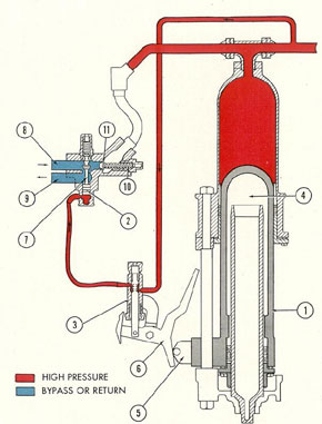
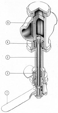
e. Pilot valve. The pilot valve (see Figure 3-14) is used in the main hydraulic system to operate the automatic bypass valve by directing oil under pressure to the automatic bypass valve piston when the accumulator is fully charged, thereby opening the bypass and then venting off this oil when the accumulator is discharged, allowing the bypass to close again.
3-14. Pilot valve.
Figure 3-15 shows a cutaway view of this valve. It is mounted on or near the accumulator in such a way that the operating arm (6) is actuated by a cam roller mounted on the accumulator plunger. Hydraulic fluid from the accumulator under pressure enters the valve at the supply port (7). As the accumulator is charged, the plunger moves downward, carrying with it the cam roller. As the plunger approaches the bottom of its stroke, the cam will bear against lower end of the pilot valve operating arm, pushing the piston (2) up within cylinder (1). In this position, the flat-milled surface (2) cut along side of the piston will allow a column of oil to pass from the supply port (7) through the
51
port (8) leading to the automatic bypass
valve.
This will open the automatic bypass
valve, bypassing the pressure oil from the
discharge side of the IMO pump back to the
suction side of the pump and allowing the
nonreturn valve to close. No more oil will be
delivered to the accumulator as long as the
pilot valve remains in this position.
When the oil charge in the accumulator
is depleted either by the use of oil required
for operation of various units in the system,
or by leakage, the plunger rises. This causes
the cam roller to bear against the upper end
of the pilot valve operating arm, thus depressing
the pilot valve piston until the land between
the two flat-milled surfaces on the
piston blocks off the supply port (7) from the
port (8) leading to the automatic bypass
valve. At the same time, the upper flat surface
(10) now aligns the port (8) with the escape
Figure 3-15. Cutaway of pilot valve.
1) Body; 2) piston; 3) packing; 4) gland nut; 5) pin;
6) pilot valve operating arm; 7) port from high pressure line;
8) port to automatic bypass; 9) to oil
supply tank; 10) flat-milled passage; 11) Mounting
bracket; 12) flat-milled passage.
port (9), and the oil trapped under pressure
in the line leading to the automatic bypass
piston is vented out through the port (9) to
a vent line which bleeds into the main supply
tank.
This removes the pressure from under the
valve piston of the automatic bypass, permitting
the loading spring to reseat the
automatic bypass valve and thus shut off the
bypass line.
Immediately pressure oil from the IMO
pump, once more directed against the underside
of the nonreturn valve, opens this valve,
allowing the oil to flow to the accumulator.
A packing gland with chevron packing
(3) prevents oil leakage past the pilot valve
piston at its point of entry into the valve
body.
The foregoing description applies only
to the latest types of pilot valves, since earlier
pilot valves are different both in design and
installation. The earlier type valve, while
serving the same purpose and designed on the
same general principle as the later type, has
two structural differences. (1) it uses a spool
piston and has its accumulator and automatic
bypass line reversed from the later pilot valve
installation; and (2) the drilled passage in the
center of the piston actually allows the venting and releasing of the oil pressure from the
automatic bypass valve. This reversal of lines
uses the automatic bypass line to be blanked
off as the piston rises rather than when the
piston descends as in the later type. The purpose
of this change in the later pilot valve is
to have the toggle switch, that automatically
starts and stops the pumps, operated by the
cam attached to the pilot valve bracket arm.
This change also provides for more positive
action of the pilot valve.
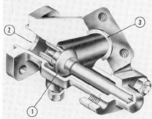
f. Automatic bypass and nonreturn
valves. 1. The automatic bypass and nonreturn
valves (see Figure 3-16) are installed
between the IMO pumps and the accumulator.
There is one on each pump pressure line. The
automatic bypass valve bypasses hydraulic
oil when the accumulator is fully charged.
The nonreturn valve prevents back-flow of
the oil to the pump.
52
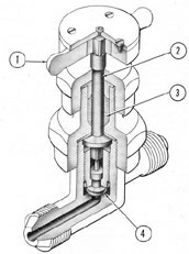
2. As seen in Figure 3-17, the valve body
(1) contains two valve parts. One is the bypass valve (2) which is held on its seat by the
valve spring (3). The other valve is of the
disk-type (4) which is also seated by a spring
(5).
Figure 3-16. Automatic bypass and nonreturn valve.
3. During the intervals when the accumulator is being charged, hydraulic oil is delivered by the pump into the pressure line (8).
The oil pressure unseats the spring-held nonreturn valve disk (4) and oil under pressure
goes into the line (7) to the accumulator.
When the accumulator is fully loaded, the
pilot valve is tripped and oil enters the bypass valve at port (9). The force of this pressure opens the bypass valve (2) and the oil
from the pumps is bypassed back to the suction side of the pumps through port (6).
When this occurs, there is not enough pressure to keep the nonreturn valve (4) off its
seat, so the disk valve spring (5) returns the
disk to its seated position, thus blocking the
back-flow of oil from the accumulator. Oil
pressure from the accumulator also assists in
the seating of the valve.
g. Miscellaneous valves. Brief mention
should be made of a group of cut-out and
check valves found in the main hydraulic system as well as in the steering and planes systems.
1. Sound isolation: supplementary nonreturn valves. If the noise of the IMO
pumps in operation were transmitted to the
hull of the submarine, it would greatly increase the danger of detection by enemy listening devices. The pumps are therefore
mounted on rubber. This precaution, however,
would be of comparatively little value if rigid
pipelines connected the pumps with the rest
of the system, since then the piping would
carry the vibration to the framework and
thence to the hull.
Accordingly, the pump noise is isolated
by inserting short lengths of flexible rubber
tubing in the hydraulic pipelines between the
automatic bypass and nonreturn valves and
the accumulator.
Rubber hose is, of course, subject to deterioration and lacks the strength of the rigid
parts of the system. Hence, the flexible connection represents a weak point in the piping.
An examination of the schematic piping diagram (Figure 3-1) will show that if either of
those connections were to give way, and no
Figure 3-17. Cutaway of automatic bypass and
nonreturn valve.
1) Body; 2) bypass valve; 3) bypass valve spring;
4) nonreturn valve disk; 5) nonreturn valve spring;
6) to pump suction; 7) to accumulator; 8) from pump;
9) from pilot valve.
53
provisions were made for shutting off the
lines between the accumulator and the automatic bypass and nonreturn valves, oil stored
in the accumulator would instantly be discharged into the pump room with accompanying hazard and inconvenience. To prevent
backing up of oil from the accumulator in this
eventuality, an additional nonreturn valve is
placed in each of these lines. The schematic
piping diagram shows the location of these
valves (11, Figure 3-1).
Figure 3-18, the internal structure of a
nonreturn valve, shows that this valve is practically identical with the nonreturn valve
which forms part of the automatic bypass and
nonreturn valve assembly (see Figure 3-17),
except that it has no return spring. The pressure oil coming from the automatic bypassand nonreturn valve enters these nonreturn
valves at the intake port (2), pushing the
valve disk (1) off its seat and allowing the
oil to flow out through the outlet port (3),
into the line leading to the accumulator.
The instant that the pressure through this
valve is reversed, oil flowing in through the
outlet port (3) would immediately force the
disk (1) back against its seat, shutting off the
line.
2. Quick-throw cut-out valve. This valve
(see Figure 3-19) is similar in operation
to the cut-out valve in the main supply manifold described in Section 3B2d. The handle
(1) rotates a stem (2) which is attached to a
valve plug (5), either to line up the port in
the plug with the fluid flow or to turn the plug
to prevent flow. The plug is tightly held on
its seat by a spring (4). The handle must be
raised to allow the plug to lift far enough to
be rotated and then released so it can be reseated. This type of quick-throw cut-out
valve is located in the pump supply lines from
the supply tank.
3. Hydraulic cut-out valves. A smaller
type of cut-out valve is illustrated in Figure
3-20. The nonrising stem (2) is rotated by a
wheel fitted with finger knobs (1). Both ends
of the stem are square, the top end fitting into
the finger wheel from which the knobs extend
and the bottom end fitting into a threaded
piece which bears against the valve disk (4).
up or down as a result of being turned left
or right by the squared lower end of the stem,
the disk will ride with it. Therefore, rotating
this stem by means of the finger wheel will
cause the male threaded piece to be screwed
downward, seating the valve disk and shutting off the flow of oil.
The valve disk has a hole drilled partially
through its center into which fits a small
cylindrical rod, extending downward from the
squared lower end of the stem. This rod
serves as a guide upon which the valve disk
slides up or down with the rotation of the
threaded piece.
Oil leakage past the stem is prevented
by packing (3), held in place by a gland.
An indicator plate at the top of the valve
(not shown in the illustration) shows which
way to turn the wheel in order to open or
close the valve.
4. Hydraulic Silbraz valves. Several of
these valves (see Figure 3-21) are located
throughout the hydraulic system. They range
in size from 1/8-inch to 1/4-inch. This valve
is of the on-and-off type in which the valve
position is secured by a lock cap. It
consists essentially of a valve body, or bonnet,
containing an upper and lower chamber which
can be opened to each other by raising the
valve disk (5, Figure 3-21), or closed by
lowering the disk down into its seat. The
disk is moved up and down by a traveling
stem (4), the top end of which is squared,
and the lower end threaded. The square
top of the stem fits loosely inside the turn-nut
(1). The lower end of the stem is formed
into a double collar to hold the valve disk (5),
within which it can turn freely. Turning
the stem left or right, therefore, will cause
it to travel up or down, thus raising or
lowering the valve disk, which rides on its
lower end.
The turn-nut is secured in any required
position by screwing the locking cap (2)
down tightly to it, using for this purpose
the large-end hex-wrench. Therefore, before
the turn-nut can be moved, the locking cap
must be backed off a little, until the turn-nut
is freed. The small end of the hex-wrench
is then applied to the turn-nut. Turning
the turn-nut all the way to the right will
screw-the stem down to its lowest position,
seating the valve disk and blocking off the
upper and lower chambers from each other,
thereby shutting off the line through the
valve. Turning the turn-nut to the left will
raise the disk, opening the valve.
Oil leakage is prevented by packing (3),
held in place by the packing gland.
It should be noted that though it is the
turn-nut to which the wrench is applied, the
turn-nut itself does not travel up or down,
it merely turns left or right, while the stem
rides up or down within it.
3B3. Operation. a. Preliminary steps. With
all units arranged in place as shown in Figure
3-1, the following steps must be taken before
the power generating system is started.
1. The entire system must be filled with
oil and the accumulator fully charged. An
additional 35 gallons, over and above the
amount necessary to fill the entire system,
must be placed in the main supply tank.
2. The back-pressure, or volume, tank
must be charged with compressed air at a
pressure of from 10 to 25 pounds per square
inch, from the 200-pound air service line.
(Not all classes of submarines have this unit.)
3. All hand levers on the control manifolds must be placed in the HAND position.
4. The quick-throw cut-out valves at the
main supply tank and main supply manifold
must be opened.
5. The air cylinder in the accumulator
and the air bottle must be charged with compressed air to a pressure of 1750 pounds per
square inch from its high pressure service
line, raising the plunger in the accumulator
to its top position.
6. The hand bypass valve on the main
system manifold may be opened if required.
b. Starting pumps. Turn on the motor
switches which start the pumps. In a few
seconds, the pumps should be operating at
full speed and the hand bypass valve (if
opened) can be closed, making possible full
development of oil pressure.
c. The accumulator (see Figure 3-8) is
charged with oil under pressure. As this
occurs, the plunger (1) is forced down until
it reaches the fully loaded position shown in
this illustration. The cam roller (5) moves
downward with the plunger and changes the
position of the pilot valve operating arm (6).
The piston of the pilot valve (3) moves up
so that the port which allows oil to flow to
the automatic bypass valve is uncovered. This
oil acts upon the automatic bypass valve
(7), forcing it upward off its seat. Hydraulic
oil which enters the automatic bypass and
nonreturn valve from the pump pressure
line (8) is bypassed to the suction side of
the pump through the port (9). In the meantime, the nonreturn valve (11) is seated because of the reduction in pump pressure
caused by bypassing the oil, and the flow of
oil from the IMO pumps to the accumulator
is shut off.
d. When the accumulator is discharged,
nearly all its contents being used in the operation of the hydraulic system, the plunger
again rises to the position shown in Figure
3-9. The cam roller, acting upon the arm of
the pilot valve, lowers the piston so that oil
no longer flows to the bypass valve (7), while
the small quantity of oil under pressure
trapped in the line between the bypass and
Figure 3-22. Contact makers for pump controls.
1) Accumulator; 2) cam and cam roller; 3) pilot
valve; 4) pilot valve control arm; 5) contact makers;
6) motor switches.
56
the pilot valve vents off through the pilot
valve vent line back to the main supply tank.
The spring will then reseat the automatic
bypass valve. Oil from the pressure side of
the pump unseats the-nonreturn valve (11)
and once more charges the accumulator.
e. During the periods when pressure is
being built up in the accumulator, the two
IMO pumps can be operated jointly, if required. In more recent classes of boats, this
is accomplished automatically. Figure 3-22
shows a typical installation. A pair of contact
makers, one for each pump, is mounted so that
they are in contact with the bracket arm of
the pilot valve. When the accumulator is in
the unloaded position, the cam on the pilot
valve operating arm releases both contact
makers, and both pump motors are switched
on at proper intervals. In the fully loaded
position, the cam presses in both of the contact makers, shutting off both pumps at
proper intervals.
C. FLOOD AND VENT CONTROL SYSTEM
3C1. General. The ability of a submarine
to attain neutral buoyancy, so that by suitable
manipulation of its diving planes it can submerge, surface, or maintain a given depth, is
effected by a series of tanks built around the
pressure hull. These tanks are divided into
separate compartments, which can be filled
with sea water to submerge the vessel, and
emptied by compressed air to restore positive
buoyancy. The tanks are classified and named
according to their normal functions as follows:
a. Main ballast tanks. The main ballast
tanks (M.B.T.) comprise e principal group.
They contain air when the vessel is surfaced,
sea water when it is submerged.
b. Fuel ballast tanks. The fuel ballast
(F.B.) tanks normally carry fuel for the
Diesel engines. When the fuel has been consumed, they can be converted for use as normal ballast tanks.
c. Negative and safety tanks. 1. The
negative tank. The negative tank is a special-purpose tank located under the control room,
just forward of amidships. When opened to
the sea, it fills up with water. It is used to
get the vessel under rapidly, or if the vessel
is already submerged, to make a quick descent
to greater depth. It is called the negative
tank because its purpose is to, provide negative buoyancy.
2. The safety tank. The safety tank is
another special-purpose tank, located amidships. Its function is the opposite of that of
the negative tank; that is, it provides positive
buoyancy in an emergency situation. Specifically, it is designed to hold a quantity of
water equal to the quantity which would flood
the conning tower as a result of enemy action.
In such case, the amount of positive buoyancy supplied by blowing the safety tank
would just compensate for the amount lost
by the flooding of the conning tower.
A special feature of both tanks is that
they are constructed as strongly as the pressure hull itself, and hence can withstand full
sea pressure at any working depth. Therefore,
whenever it is necessary either to surface or
to attain a shallower depth, the full working
pressure of the high pressure air line can be
let into these tanks, rapidly expelling the
water.
d. The bow buoyancy tank. The bow
buoyancy tank, as its name implies, is located
in the bow of the vessel, and controls-its buoyancy. When the ship dives, this tank is
flooded first to make the ship nose-heavy;
when surfacing, it is blown out first, to make
the ship rise by the bow.
3C2. Detailed description. a. Flood valves
and vent valves. All main ballast tanks have
flood ports; the fuel ballast tanks have hand-operated flood valves. All have hydraulically
operated vent valves.
The vent valve on the safety tank and the
flood valves on the safety and negative tanks
normally are hydraulically operated, but if
necessary, can also be operated by hand.
The vent valve on the negative tank is
hand-operated and is vented inboard.
When the submarine is surfaced, the
vents are closed, and the water is kept out of
the tanks by keeping them filled with air at
about 10 pounds pressure. Since the flood
57
ports of the main ballast tanks are always below the waterline, the sea exerts a constant
upward pressure, but is prevented from entering because the imprisoned air cannot escape.
To submerge the vessel, therefore, it is necessary only to open the vents, allowing the imprisoned air to escape, and the sea water will
enter the tanks.
To surface again, the vents are closed,
and air is forced into the tanks from the top,
blowing the water out through the flood ports
in the bottom.
b. Flood and vent control manifolds.
The main ballast, fuel ballast, and safety tank
vent valves, and the bow buoyancy and the
two hydraulically operated flood valves
(safety and negative tanks) are controlled
from two flood and vent control manifolds,
the six-valve manifold and the three-valve
manifold, both located in the control room.
1. The main vent control manifold. a.
Portsmouth installation. Figure 3-24 shows
the main vent control manifold, commonly
called the six-valve manifold, as installed on
boats of Portsmouth design. It is a housing
containing six identical control valves, each
one of which is separately operated by individual hand levers.
Reading from right to left (Figure 3-24),
these six levers operate the following vent
valves:
1) Bow buoyancy tank
2) Main ballast tanks No. 1 and No. 2
3) Fuel ballast tanks No. 3 and No. 5
4) Main ballast tank No. 4
5) Main ballast tanks No. 6 and No. 7
6) Safety tank
b. Electric Boat Company installations.
The main vent control manifold on boats
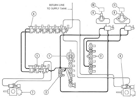
Figure 3-23. Piping diagram of flood and vent system and periscope and antenna mast hoists.
1) Main supply manifold; 2) main return manifold; 3) two-valve addition to main supply manifold, for periscope hoist and antenna hoist (in practice welded to lower end of main manifold); 4) main vent control, or six-valve, manifold; 5) flood and hull ventilation control, or three-valve, manifold; 6) vent valve operating gear, bow buoyancy tank; 7) main engine air induction and hull ventilation; 8) periscope vent line; 9) antenna vent line; 10) settling tank; 11) settling tank.
58
built by the Electric Boat Company houses
seven control valves instead of the six found
in the Portsmouth installation.
Reading from right to left, these seven
valves operate the following vent valves:
1) Bow buoyancy tank
2) Main ballast tanks No. 1 and No. 2
3) Fuel ballast tanks No. 3 and No. 5
4) Main ballast tank No. 4
5) Safety tank
6) Main ballast tank No. 6
7) Main ballast tank No. 7
c. Operation of the valves. Each valve
has four positions, which are shown on indicator plates next to the hand levers:
1) CLOSE, which closes the vent.
2) OPEN, which opens it.
3) HAND, which bypasses the oil allowing hand operation.
4) EMERGENCY, which shuts off the
lines to the hydraulic unit cylinder, so that
if there is a break in the local circuit, oil will
not leak out of it from the main system, and
only the oil in the local circuit will be lost.
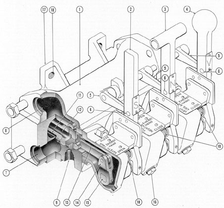
Figure 3-24. Main vent control manifold (six-valve manifold).
The frame mounted on the manifold has
notches cut into it for each valve position.
The hand lever is firmly latched into these
notches by a lateral spring. Once placed in
any position the lever remains there until
moved by the operator.
Each of these control valves operates a
flood or vent valve, at some point remote from
the manifolds, by directing a column of pressure oil to one side or the other of a hydraulic unit cylinder whose piston is connected,
through suitable linkage, to the valve operating mechanism.
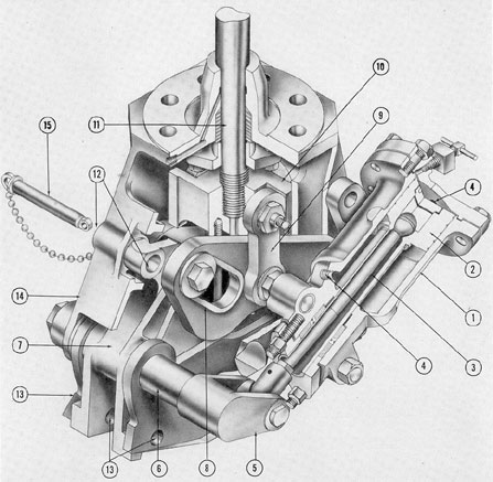
Figure 3-25 shows the internal construction of one of these valves, as it would look
from the left end of the manifold. (The illustration shows the three-valve manifold, but
the internal structure of its valves is identical
with those in the six-valve manifold.) It is
a spool-type valve, so called because of the
spool (11) which, when moved by the hand
lever (2), shaft (15), arm (14), and connecting
link (13), opens and closes the required combinations of ports and channels in the body
(1) of the valve. The pressure line (7) and
the return line (8) form channels which run
lengthwise through the whole manifold; the
threaded port (9) on the bottom of the manifold goes to the upper end of the hydraulic
unit cylinder; a similar port just behind it
(not shown) goes to the lower end of the
cylinder. The latching spring (10) holds the
hand lever firmly in place. The individual
locking arms (5) swing freely on the pivot
rod, making a sliding fit against the side of
the hand lever, just tight enough to prevent
the lever from being pulled out of the notch.
Therefore, the hand lever cannot be moved
from any of the four notched positions while
its locking arm is down, that is, horizontal.
The lock hole (6) is just above the top of the
locking arm when it is horizontal so that, to
secure a valve in any position, it is necessary
only to place the hand lever in the desired
notch, drop the locking arm, and slip a padlock through the locking hole. In this view,
Figure 3-25, the three locking arms are viewed
from the left end of the manifold and shown
in the dropped position. Reference to Figure
3-24, in which they are shown partly raised,
and viewed from the right end, will make the
arrangement more easily understood.
2. The flood and hull ventilation manifold. Figure 3-26 shows the flood and hull
ventilation manifold, usually called the three
valve manifold. Its three control valves are
identical in structure and operating principles
with those on the six-valve manifold just described (see Figure 3-25). Its hand levers are
all shaped differently, however, and its functions differ in important ways from those of
the six-valve manifold.
59
Reading from right to left (Figure 3-26),
its three hand levers operate the following
units:
a) Main engine. Engine air induction
and hull ventilation supply and exhaust.
(Ball-shaped handle; name plate V.)
b) Negative tank flood valve. (T-shaped
handle; name plate N.)
c) Safety tank flood valve. (Straight
handle; name plate S.)
As on the six-valve manifold, each valve
has four positions, shown on indicator plates
next to the hand levers:
a) CLOSE, which closes the hydraulically operated unit.
b) OPEN, which opens it.
c) HAND, allowing hand operation.
d) EMERGENCY, which shuts off the
lines to the hydraulic unit cylinder in case of
a break in them, so that the oil in that circuit
only will be lost.
Figure 3-25. Cutaway of safety and negative flood, engine air induction and hull ventilation control manifold (three-valve manifold).
1) Valve manifold body; 2) hand lever for flood valve of safety tank; 3) hand lever for flood valve of negative
tank; 4) hand lever for hull ventilation valve and engine air induction valve; 5) locking arms; 6) hole for
padlock; 7) hydraulic port from supply line, main hydraulic system; 8) hydraulic port to return line; 9) hydraulic port to hydraulic cylinder of operating gear; 10) latching spring; 11) spool; 12) bypass channel in
valve; 13) link; 14) arm; 15) shaft; 16) drain plug; 17) bracket; 18) mounting hole.
60
The units operated by this manifold are
extremely important to the safety of the vessel and the following precautions have been
taken to prevent errors in its operation:
a) As already shown, its handles are so
shaped as to be instantly identifiable, even in
the dark.
b) The safety and negative tank flood
valve levers throw in opposite directions from
each other for CLOSE or OPEN (see name
plates in Figure 3-25).
c) The main engine air induction and
hull ventilation valve lever (with ball-shaped
handle) is fitted with a spring-loaded pin
which will lock it when placed in the
CLOSE position (see Figure 3-26). In order
to move this lever to OPEN, this pin must
be pulled out and held out while the lever is
being moved. In other words, it takes both
hands to move this lever out of either position.
In addition, the three-valve manifold has
the regular latching and locking devices described in connection with the six-valve manifold.
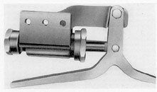
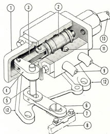
c. The vent valve operating gear. All
vent valves on the main ballast tank system
and the valve on the safety tank and bow
buoyancy tank are hydraulically operated.
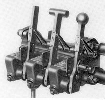
Figure 3-26. Safety and negative flood, engine air
induction and hull ventilation control manifold (three-valve manifold).
The operating gear is shown in Figure
3-27. It consists essentially of a hydraulic
unit cylinder and suitable linkage connecting
it to a vertical operating shaft which opens
and closes the vent. It can also be operated
by the hand lever (shown projecting downward in the illustration).
Figure 3-27. Vent valve operating gear and hydraulic
unit cylinder.
61
A cutaway view of the same mechanism
is shown in Figure 3-28. Fluid under pressure is admitted from the control valve into
the hydraulic unit cylinder (1) through the
ports (4). As the piston head (2) moves, it
actuates the crankshaft (6). This moves the
cam, which, bearing against the groove in the
slotted link (8), causes that link to push up
or pull down on the flat link (9), thereby
moving the crosshead (10) up or down. Into
the top of the crosshead is screwed the lower
end of the operating shaft (11). This shaft
goes up through a packing gland in the pressure hull, to the superstructure, where the
mechanism which opens and closes the vent
is located. Figure 3-28 shows the mechanism
as it would look with the vent closed.
The mechanism is furnished with a locking pin (15), attached to the framework by a
chain. This pin is placed in one of three holes,
Figure 3-29. Diagram of vent control valve and cylinder, OPEN.
1) Hand lever; 2) control valve; 3) return port; 4) supply port; 5) return channel; 6) port to upper end
of cylinder; 7) port to lower end of cylinder; 8) bypass channel of control valve; 9) spool; 10) equalizing
bypass; 11) upper port in cylinder; 12) lower port in cylinder; 13) hydraulic unit cylinder; 14) piston;
15) piston rod; 16) crankshaft; 17) cam; 18) slotted link; 19) connecting link; 20) operating shaft; 21) locking
pin; 22) chain for locking pin; 23) locking hole for POWER position; 24) hand-operating lever; 25) handle
locking bracket; 26) locking hole for HAND position; 27) piston guide sleeve.
labeled respectively POWER, HAND (13),
and LOCK (12), and identified by adjacent
indicator plates.
When the pin (21, Figure 3-29) is placed
in the POWER hole (23), the hand-operating
lever (24) is locked in the stowed position,
and the vent is operated by the hydraulic unit
cylinder.
When placed in the lock holes for the
HAND position (26, Figure 3-29), the pin
bolts the hand-operating lever solidly to the
linkage, so that moving the lever (24) will
actuate the mechanism and operate the vent.
When placed in the lock hole for the
LOCK position-which can be done only
when the valve is closed and the hand lever
stowed-the pin locks the operating shaft so
that it cannot be moved.
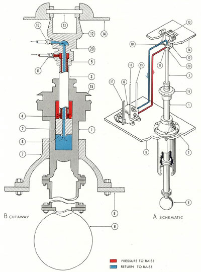
d. The hydraulic flood valve operating
gear. The flood valves on the safety and
negative tanks are hydraulically operated by
the mechanism shown in Figure 3-30. The
crossarm and hand grips shown are for hand
operation in case of failure of the hydraulic
power.
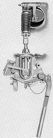
Figure 3-30. Flood valve operating gear and hydraulic
cylinder.
63
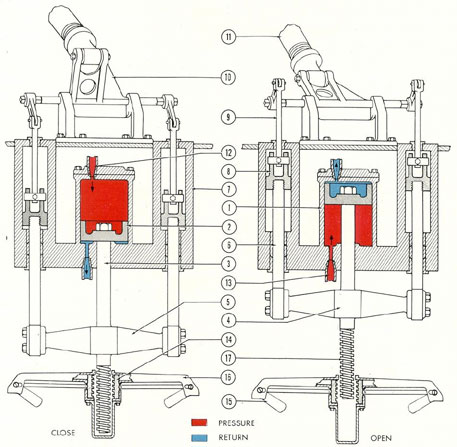
Figure 3-31 is a diagram of this mechanism. It is essential to understand that the
main piston rod (3) and the tie rods (6) are
yoked rigidly together through the crosshead
(4). Impelled by the hydraulic pressure
against the piston head (2), all three rods
move inward or outward as a unit.
Two positions, OPEN and CLOSE, are
shown in the diagram. Oil under pressure
from the control manifold is shown in red,
return oil in blue; direction of flow is indicated by arrows.
1. To open the valve, hydraulic fluid from
the control valve is admitted through the port
(13), moving the piston head (2) outward ( up
in the diagram). The motion is communicated
through the crosshead (4). The tie rods (6),
screwed rigidly into this crosshead, are
Figure 3-31. Diagram of flood valve operating gear and hydraulic cylinder in OPEN and CLOSE positions.
1) Hydraulic unit cylinder; 2) piston; 3) main piston rod; 4) crosshead; 5) yoke; 6) tie rod; 7) guide cylinder;
8) guide piston; 9) outboard connecting rods; 10) crank; 11) operating shaft; 12) hydraulic port, pressure
to close flood valve; 13) hydraulic port, pressure to open flood valve; 14) half-nut; 15) hand grips; 16) crossarm; 17) threaded shaft.
64
pushed outward; the outboard connecting
rods (9), through the crank (10), push the
operating shaft (11) out, opening the flood
valve (not shown). Return oil meanwhile
flows out through the other port and back to
the control valve.
2. To close the valve, the flow of hydraulic fluid is reversed, pushing the piston inward ( down in the diagram).
3. To operate the mechanism by hand,
the hand grips (15) are pulled outward (to
the position shown in Figure 3-30). This
meshes the half-nut (14) with the threaded
shaft (17). Turning the crossarm (16) will
then cause the shaft to travel.
4. The guide cylinders (7) are watertight.
The guide pistons (8) slide through greased
packing into the tank.
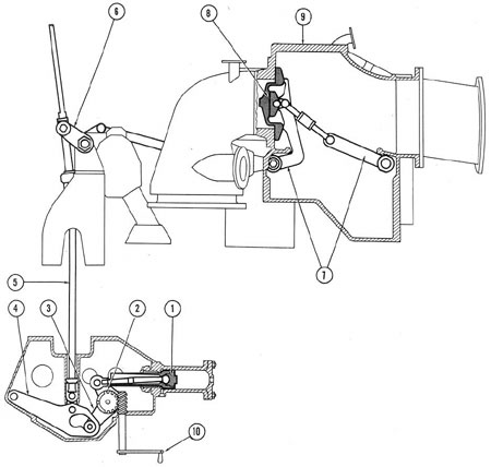
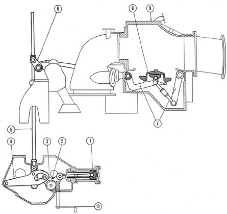
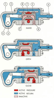
e. Operation of vent valves. Figures
3-29, 3-32, 3-33, and 3-34 illustrate the operation of a vent by any valve on the six-valve
manifold (see Figure 3-24). In all cases, oil
from the supply line of the main hydraulic
system is shown in red, oil to the return line
in blue, and inactive oil in lighter red. Direction of flow is indicated by arrows.
Figure 3-29 shows the hand lever (1) of
the control valve (2) in the OPEN position.
The spool (9) directs oil from the supply
port (4) to the port (6) into the line leading
to the upper port (11) of the unit cylinder
Figure 3-32. Diagram of vent control valve and cylinder, CLOSE.
1) Hand lever; 2) control valve; 3) return port; 4) supply port; 5) return channel; 6) port to upper end of
unit cylinder; 7) port to lower end of unit cylinder; 8) bypass channel of control valve; 9) spool; 10) equalizing
bypass; 11) upper port in cylinder; 12) lower port in cylinder; 13) hydraulic unit cylinder; 14) piston;
15) piston rod; 16) crankshaft; 17) cam; 18) slotted link; 19) connecting shaft; 20) operating shaft; 21) locking
pin; 22) chain for locking pin; 23) locking hole for POWER position; 24) hand-operating lever; 25) hand lever
locking bracket; 26) locking hole for HAND position; 27) piston guide sleeve; 28) locking hole for LOCK
position.
65
(13). The pressure lowers the piston head
(14) turning the crank (16), which actuates
the cam (17). The cam rides down in the slot
of the slotted link (18), pulling the flat link
(19) downward. This in turn pulls down the
operating shaft (20), opening the vent. Return oil, forced from the lower port (12) in
the unit cylinder, flows through the port (7)
to the return channel (5) in the control manifold body. Note that for power operation,
the hand-operating lever (24) is in the stowed
position, locked into the bracket (25) by the
locking pin (21).
Figure 3-32 shows the control valve in
the CLOSE position. The spool (9) directs
oil from the supply port (4) to the port (7)
into the line leading to the lower port (12)
of the hydraulic unit cylinder, pushing the
piston up and pulling the cam (17) up through
the slotted link (18). This raises the operating shaft (20), closing the vent. Return oil,
forced through the upper port (11) of the unit
cylinder, flows through the port (6) back into
the return channel (5) of the manifold. Note
that the hand-operating lever (24) is again in
the stowed position, and the locking pin (21)
is placed in the POWER hole (23) in the
bracket (25). In this position, with the vent
closed and the hand-operating lever stowed,
the locking pin can be placed, if required, in
the locking hole for the LOCK position (28),
thus preventing accidental opening.
Figure 3-33 shows the lever in the HAND
position. Here the bypass channel (8) in the
control valve connects the two ports (6 and 7)
leading to the unit cylinder. This allows bypassing of the oil between the upper and the
Figure. 3-33. Diagram of vent control valve and cylinder, HAND.
1) Hand lever; 2) control valve; 3) return port; 4) supply port; 5) return channel; 6) port to upper end of
unit cylinder; 7) port to lower end of unit cylinder; 8) bypass channel of control valve; 9) spool; 10) equalizing bypass; 11) upper port in cylinder; 12) lower port in cylinder; 13) hydraulic unit cylinder; 14) piston;
15) piston rod; 16) crankshaft; 17) cam; 18) slotted link; 19) connecting link; 20) operating shaft; 21) locking
pin; 22) chain for locking pin; 23) locking hole for POWER position; 24) hand-operating lever; 25) hand
lever locking bracket; 26) locking hole for HAND position; 27) piston guide sleeve.
66
lower sides of the unit cylinder (13) permitting hand operation. At the same time, the
lands on the control valve (2) have cut off the
pressure port. A special feature of the HAND
position is the small extra channel, 3/16-inch
in diameter, called the equalizing bypass (10).
This permits a very small flow of oil from the
bypass channel (8) back into the return line
when the valve is operated at CLOSE. It also
permits replenishment of oil when the valve
is in the OPEN position to compensate for
the unequal areas of the two sides of the piston. Without this compensation, opening and
closing the valve by hand would meet with
considerable resistance, because the top of the
hydraulic unit cylinder's piston (14) presents
a greater effective area to the contained oil
than does the bottom side, whose effective
area is practically negligible because of the
piston guide sleeve (27) cast integral with the
piston. Note that for hand operation the locking pin (21) is placed in the HAND locking
hole (26), so that when the hand-operating
lever (24) is moved, the linkage also moves.
Figure 3-34 shows the lever in the
EMERGENCY position. The control valve
lands completely blank off the supply port
(4) and the return channel (5) from the ports
(6 and 7) which lead to the hydraulic unit
cylinder. These lands also close the 3/16-inch
equalizing bypass (10). Thus the oil to the
hydraulic unit is completely isolated from
the rest of the system. In case of a broken
line, hand operation is possible, since the cylinder ports are bypassed to each other. However, some resistance will be encountered
because of the difference in area between the
lower and upper sides of the piston, which
was explained in the preceding paragraph.
The locking pin (21) is shown here in the
lock hole (26) for HAND operation.
Figure 3-34. Diagram of vent control valve and cylinder, EMERGENCY.
1) Hand lever; 2) control valve; 3) return port; 4) supply port; 5) return channel; 6) port to upper end of
unit cylinder; 7) port to lower end at unit cylinder; 8) bypass channel of control valve; 9) spool; 10) equalizing bypass; 11) upper port, in cylinder; 12) lower part in cylinder; 13) hydraulic unit cylinder; 14) piston;
15) piston rod; 16) crankshaft; 17) cam; 18) slotted link; 19) connecting link; 20) operating shaft; 21) locking
pin; 22) chain for locking pin; 23) locking hole for POWER position; 24) hand-operating lever; 25) hand lever
locking bracket; 26) locking hole for HAND position; 27) piston guide sleeve.
67
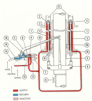
Figure 3-35. Diagram of periscope hoist approaching
fully raised position.
1) Hydraulic cylinders; 2) piston; 3) piston rods; 4) yoke for periscope;
5) periscope; 6) eyepiece; 7) control valve; 8) control valve spool;
9) tapered center of spool; 10) control valve hand lever; 11) automatic
trip; 12) actuating spindle for automatic trip; 13) supply port, from main
supply manifold; 14) return port, to main return manifold; 15) port to
hydraulic cylinders; 16) cylinder ports; 17) upper section of hydraulic
cylinders (no oil in upper section); 18) shaft; 19) packing.
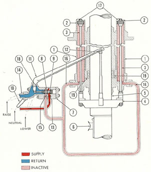
Figure 3-36. Diagram of periscope hoist in fully
raised (tripped) position.
1) Hydraulic cylinders; 2) piston; 3) piston rods; 4) yoke for periscope;
5) periscope; 6) eyepiece; 7) control valve; 8) control valve spool;
9) tapered center of spool; 10) control valve hand lever; 11) automatic
trip; 12) actuating spindle for automatic trip; 13) supply port from main
supply manifold; 14) return port, to main return manifold, 15) port to
hydraulic cylinders; 16) cylinder line; 17) upper section of hydraulic
cylinders (no oil in upper section; 18) shaft; 19) packing.
68
D. PERISCOPE AND VERTICAL ANTENNA HOISTS
3D1. General arrangement. On some later
classes of submarines, the periscope and the
vertical antenna are hydraulically operated,
as units of the main hydraulic system. Their
location is shown schematically in Figure
3-23.
Each is raised and lowered by a hydraulic
hoist. This consists essentially of a pair of
long, vertically mounted hydraulic cylinders
of small diameter, bracketed in the fairwater
above the conning tower. Two piston rods
emerge from the lower ends of the cylinders
are yoked together and carry between them,
in the yoke, the periscope or vertical antenna.
Control valves for each are located in the
conning tower. Since these units are raised
by hydraulic power and lowered by gravity,
an automatic trip arrangement reduces the
hydraulic pressure before the unit reaches
the mechanical stop at the top of its travel,
while a spring bumper at the bottom cushions
its descent.
3D2. Detailed description. a. The periscope. 1. Arrangement of hoist mechanism and
distribution of pressure. The general arrangement of the periscope hoist and hydraulic lines is illustrated schematically in Figure 3-35.
A pair hydraulic-cylinders (1) is
bracketed into the periscope fairwater, at the
top of the conning tower. The piston heads
(2) and piston rods (3) are bolted to a yoke
(4) which carries the periscope (5). In other
words, the pistons and periscope are rigidly
connected and travel as a unit. As the pistons
are raised by hydraulic pressure admitted to
the undersides of the piston heads, the periscope extending through the center of the
fairwater rises from its well and is projected
upward.
A distinctive feature of this
type of hoist
is the fact that the control valve (7 ) admits
hydraulic fluid only to the lower ends of the
cylinders. No oil is present on top of the piston heads except that which leaks past the
piston from the pressure side. Overflow lines
and a settling tank (not shown), located in
the conning tower, are provided to catch any
oil that may leak up past the piston heads.
To lower the periscope, the lines from the
ports (16) at the lower ends of the cylinders
are opened to the return line (14) and the
periscope and pistons are allowed to descend
by their own weight, forcing the oil out of the
cylinders into the return line.
2. The control valve. The control valve
(7) is a three-position spool-type valve. The
spool itself (8) has a center channel (9) with
a very fine taper (40-30), and hence the lands
do not rise at a sharp angle from the center
channel.
This tapered cut-off has the effect of
opening and closing the valve ports gradually,
preventing sudden shocks and so-called hydraulic hammer which might affect the delicate optical instruments in the periscope.
The position of the spool is controlled
by the hand lever (10). As shown in Figure
3-35, this lever has three positions, RAISE,
LOWER, and NEUTRAL. At RAISE, the
spool is pulled toward the left, admitting
pressure from the supply port (13) into the
discharge port (15) leading to the cylinder
ports (16). The return line (14) is blanked
off.
At NEUTRAL, the spool is in the intermediate position, blanking off all the ports
and hydraulically locking the periscope at
any given height.
At LOWER, the spool is pushed to the
right, blanking off the supply port (13) and
opening the cylinder line (16) to the return
port (14). This allows the oil to escape from
the cylinders into the return line by the
weight of the periscope assembly. Note that,
because of the lack of a hydraulic line to the
upper end of the cylinder, this valve needs
only three ports instead of the usual four.
3. The automatic trip. To prevent the
periscope from jolting against the mechanical
stop when it reaches the top of its travel, an
automatic trip (11) is attached to the same
shaft (18) as the hand lever (10).
This automatic trip is operated by the
spindle (12) bolted onto the yoke (4). The
69
height of the spindle and the angle of the trip
are so adjusted that, as the periscope approaches the fully raised position, the spindle
pushes up the trip, automatically moving the
tapered spool (8) toward the intermediate, or
NEUTRAL, position. This gradually cuts off
the flow of oil to the cylinders, bringing the
periscope to an easy stop.
The trip and the hand lever are solidly
connected to the same shaft (18) so that if the
operator should try to hold the lever at the
RAISE position after the spindle has reached
the trip, the trip, mechanically impelled by
the upward movement of the periscope, will
pull the hand lever out of his grasp. This
simple arrangement therefore acts as a quick,
sure, automatic cut-out.
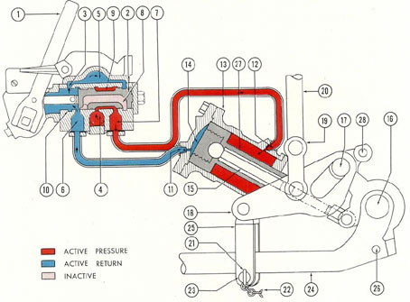
4. Explanation of Figures 3-35 and 3-36.
In Figure 3-35, the control valve is at RAISE
and the periscope has almost reached the top
of its travel. The spindle (12) is almost at
the automatic trip.
In Figure 3-36, the periscope is fully
raised and the spindle has pushed the trip and
hand lever, moving the valve to the NEUTRAL position, blanking all ports, cutting off
the flow of oil, and locking the periscope in
that position. Oil under pump pressure is
shown in red; return oil in blue; inactive oil
in lighter red. Direction of flow is indicated
by arrows.
b. The vertical antenna. The vertical
antenna hoist need not be discussed in detail,
as it is almost identical to the periscope hoist
in arrangement, structure, and operating principles.
In addition to the automatic trip arrangement for preventing a sudden stop at the top
of its travel, the vertical antenna hoist also
has a dash-pot arrangement and a piston head
with tapered grooves cut toward its underside, which help to bring it to an easy stop at
the bottom.
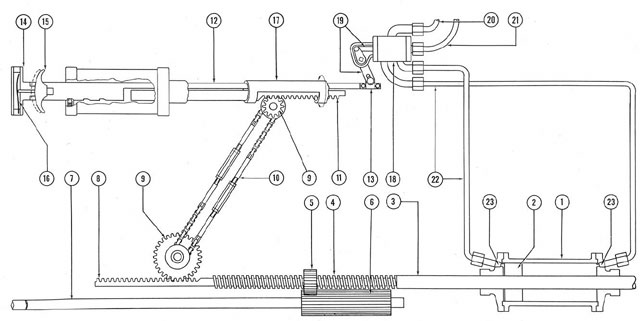
Figure 3-37. Piping diagram of forward and after service lines.
1) Main supply manifold; 2) main return manifold; 3) main engine exhaust actuating cylinder; 4) main engine
exhaust gear and exhaust valve; 5) main engine exhaust control valve; 6) torpedo tube outer door control
valve; 7) torpedo tube outer door actuating cylinder; 8) echo-ranging control valve; 9) echo-ranging cylinder;
10) bow plane rigging control valve; 11) forward service line, supply; 12) forward service line, return; 13) after
service line, return; 14) offer service line, supply; 15) control valve for forward windlass-and-capstan.
70
E. FORWARD AND AFTER SERVICE LINES
3E1. General arrangement. There are two
sets of hydraulic lines extending from the
main supply manifold and the main return
manifold to both ends of the submarine. These
lines, known as the forward and after service
lines, furnish power to a miscellaneous group
of hydraulically operated submarine equipment; specifically, these hydraulic lines supply
necessary power to the following apparatus:
a. The after service lines supply power
for the operation of:
1. Main engine drowned-type exhaust
valves.
2. Outer doors of the four after torpedo
tubes.
Figure 3-38. Cutaway of main engine drowned-type exhaust valve operating gear and hydraulic cylinder.
1) Cylinder; 2) piston; 3) connecting rod; 4) crank, 5) worm gear; 6) drive gear; 7) power shaft; 8) indicator dial; 9) pointer; 10) locking pin; 11) hand gear; 12) frame; 13) crosshead; 14) operating lugs.
71
b. The forward service lines supply power for the operation of:
1. Bow rigging.
2. Forward windlass-and-capstan.
3. Two echo-ranging and sound detection
devices, known as the sound heads.
4. Outer doors of the six forward torpedo
tubes.
Each of the above items of equipment is
operated by a hydraulic cylinder to which oil
under pressure is directed by a control valve.
The remainder of this section is devoted to a
description of the hydraulic cylinders and
control valves for the equipment listed above.
Hydraulic pressure is distributed to the
service lines at the main supply manifold by
two valves. One line is marked SERVICE
FORWARD, the other, SERVICE AFT.
The return lines terminate in two similarly
named valves of the main return manifold.
A schematic diagram of the forward and
after service lines is shown in Figure 3-37.
The diagram shows the rigging control valve
but not the equipment which operates the bow
rigging and the forward windlass-and-capstan. Although that equipment receives its
power from the forward service lines, its
description has been included in Section C of
Chapter 5.
3E2. Main engine drowned-type exhaust
valve. a. General arrangement. When the
submarine is surfaced and the main engines
are running, the engine exhaust is vented outboard. Each main engine has an exhaust
which must be opened before the engines
start and closed when the engines are
stopped. These valves are hydraulically operated as units on the after service lines.
b. Detailed description. The control
valve is of the conventional spool type, having three positions: OPEN, CLOSE, and
HAND. A control valve is provided for each
hydraulic cylinder. As the piston (2, Figure
3-38), is moved backward or forward in the
cylinder (1) by hydraulic pressure, the connecting rod (3) which is attached to a crank
(4) rotates the operating lug (14). The operating lug, in turn, moves the power shaft (7)
up or down to open or close the main engine
exhaust valve through a set of linkage arms
and cranks.
In the event of hydraulic power failure,
the hand gear (11) can be used to rotate the
drive gear through a worm (5). A locking
pin (10) holds the hand gear in place when
it is not being used.
The motion of the drive gear is indicated
by the pointer (9) which moves with it and
shows on the indicator dial (8) whether the
exhaust valve is in the OPEN or in the
CLOSE position.
c. Operation. The installation and arrangement of the hydraulic equipment for
operating the main engine drowned-type
exhaust valves vary with different classes of
submarines.
Some earlier classes of submarines have
five exhaust valves: four main engine outboard exhaust valves and one outboard exhaust valve for the auxiliary engine. The
control valves are arranged in two manifolds.
The after engine room has a manifold of three
control valves, and the forward engine room,
a manifold of two valves.
The more recent type of submarine, however, has only four main engine outboard exhaust valves. There is no separate exhaust
valve for the auxiliary engine, its exhaust
being expelled through one of the main engine exhaust valves-main engine No. 4 on
the Electric Boat Company submarine and
main engine No. 3 on the Portsmouth submarine. The control valve for both main engine outboard exhaust valves in each engine
room is located near the throttle, on the port
side of that engine room, so that the engine
operator can manipulate both exhaust valve
controls simultaneously.
Figures 3-39 and 3-40 show a main engine
drowned-type exhaust valve in the CLOSE
and OPEN positions, as well as the connecting linkage between it and the hydraulic
cylinder.
When the control valve handle is brought
to the CLOSE position, the exhaust valve and
actuating cylinder are in the condition shown
in Figure 3-39. Hydraulic pressure pushes
72
the piston (1) to the left, rotating the crank
(3) so that it pulls down the cam lever (4).
This action moves the power shaft (5) and
shaft linkage (6) downward, and forces the
exhaust valve (8) upward by means of the
connecting linkage (7).
Moving the control valve handle to
OPEN admits fluid into the hydraulic cylinder to move the piston to the right as shown
in Figure 3-40, the OPEN position. This
rotates the crank (3) so that the cam lever (4)
is raised, lifting the power shaft (5) and the
shaft linkage (6) which pulls the exhaust
valve (8) downward by means of the valve
linkage (7), thus opening it.
The valve operating gear just described
will be found in all later classes of Portsmouth submarines. On the Electric Boat
Company submarines, the main engine
exhaust valves are operated by a hydropneumatic system, consisting of a small independent hydraulic system for each valve, to
which pressure is provided by compressed
air.
Figure 3-39. Diagram of main engine drowned-type exhaust valve operating gear and hydraulic cylinder, CLOSE.
1) Piston; 2) drive gear; 3) crank; 4) cam lever; 5) power shaft; 6) shaft linkage; 7) valve linkage;
8) exhaust valve; 9) exhaust valve housing; 10) hand gear.
73
To operate the valve, the air is admitted
on top of an oil reservoir, which in turn is
connected to the hydraulic cylinder.
The air, acting upon the oil, forces it into
the cylinder where it moves the piston to
open or close the exhaust valve.
3E3. Torpedo tube outer door mechanism.
a. General. The torpedo tube outer doors
are hydraulically operated as separate units
from the fore and aft service lines. There are
ten torpedo tubes in all, six forward and four
aft. Their location is shown schematically in
the fore and aft service line piping diagram,
Figure 3-37.
The outer door operating mechanism consists essentially of the hydraulic cylinder,
piston, and power shaft; the control valve and
operating handle; and a jackscrew for hand
operation. All parts are mounted on the torpedo tube itself and controlled from its
breech.
1. The control valve. The control valve
is a three-position spool-type valve. Figure
3-41 shows its internal structure. The operating lug (7) is moved back and forth when
Figure 3-40. Diagram of main engine drowned-type exhaust valve operating gear and hydraulic cylinder, OPEN.
1) Piston; 2) drive gear; 3) crank; 4) cam lever; 5) power shaft; 6) shaft linkage; 7) valve linkage;
8) exhaust valve; 9) exhaust valve housing; 10) hand gear.
74
the handle is pushed in or out. This in turn
moves the slotted link (6), rotating the shaft
(5) and the arm (4). The arm moves the connecting link (3) which moves the valve (2)
inside the valve body (1), opening and closing
the required combination of ports. The ports
(9) lead to opposite ends of the hydraulic
cylinder; the return port (10) leads to the
fore and aft service lines. The supply port
is not shown in this view.
Figure 3-41. Cutaway of outer door control valve.
1) Valve body; 2) valve; 3) connecting link; 4) arm;
5) shaft; 6) slotted link; 7) operating lug; 8) connecting rod (to handle); 9) cylinder ports; 10) return
port (to main hydraulic system); 11) channel from
supply port (from main hydraulic system; port not
shown in this illustration); 12) mounting bracket.
Figure 3-42 shows the control valve in
each of its three positions: OPEN, in which
the pressure line (7) is opened to the inner,
or breech, end of the hydraulic cylinder, and
the return line (8) is opened to the outer end;
CLOSE, in which these connections (pressure
and return) are reversed; and HAND, in
which the pressure ports leading to the
cylinder (9) are connected to each other, bypassing the oil in the cylinder. The pressure
side is shown in red, the return side in blue;
inactive oil is shown in lighter red. The
direction of flow in each position is shown by
arrows.
2. General arrangement. The considerably simplified general arrangement of the
mechanism as a whole is shown in Figure 3-43.
The hydraulic cylinder (1) contains a piston
(2) which is moved by hydraulic power. It
is connected rigidly to the power operating
shaft (3) whose motion opens or closes the
outer door. The hydraulic power is directed
to one side or the other of the hydraulic
cylinder by the control valve (18). This allows flow of hydraulic power from the supply
side (20) of the forward or after service lines
Figure 3-42. Diagram of outer door control valve in
three positions.
1) Valve body; 2) valve; 3) link; 4) arm; 5) shaft;
6) bypass channel in valve; 7) channel to supply port
from main hydraulic system; 8) return port (to main
hydraulic system); 9) cylinder ports (to actuating
cylinder).
75
Figure 3-43. Schematic diagram of outer door operating mechanism.
1) Hydraulic cylinder; 2) piston; 3) power operating shaft; 4) jackscrew or threaded portion of shaft; 5) jack-nut; 6) hand shaft driving gear; 7) hand-operated shaft; 8) rack on power operating shaft; 9) spur gear; 10) sprocket chain; 11) rack on outer slide (breech and outer door interlock);
12) inner slide; 13) operating lug; 14) operating handle; 15) trigger; 16) spring; 17) ready-to-fire interlock tube; 18) control valve; 19) linkage
on control valve; 20) supply from forward or after service line; 21) return to forward or after service line; 22) lines to hydraulic cylinder; 23) ports
in hydraulic cylinder.
76
and feeds it back to the return side (21). The
control valve is operated by the operating
handle (14), a push-pull arrangement which
slides in and out lengthwise through the
ready-to-fire interlock tube, a section of which
(17) is shown. The operating handle is connected to the control valve by the inner slide
(12) which is attached to the control valve
linkage (19) by the operating lug (13).
3. The interlocks. Safe operation of a
torpedo tube is a delicate and complicated
process. It involves several different conditions which cannot be allowed to occur simultaneously. For example, it is obvious that
when the outer door is opened to the sea, the
inner door must be locked shut, and vice
versa. The tube must not be made READY-TO-FIRE unless different interlocks, not
shown in full detail in the schematic diagram,
are properly engaged. At the end of the
power operating shaft (3) is a spur tooth
rack (8) which, through a pair of spur gears
(9), sprocket chain (10), and a similar spur
tooth rack (11) on the outer slide, operates
the ready-to-fire interlock (not shown). The
ready-to-fire interlock is connected to the
tube (17) which rotates around the inner and
outer slides and also serves as a guide tube.
4. Hand operation of outer doors. For
hand operation of the outer doors, a hand-operating shaft (7) is provided, with a squared
end over which fits an operating crank. This
turns the hand shaft driving gear (6). This
gear is meshed with the jack-nut (5), which
in turn is threaded into the threaded portion
(4) of the power operating shaft. Therefore,
as the jack-nut is turned, the power operating
shaft will travel through it, opening or closing the outer door. In order to operate this
by hand, the control valve (18) must be in
the HAND position, so that the fluid trapped
in the hydraulic cylinder (1) will not act
as a hydraulic lock against the motion of the
piton (2).
The operating handle (14), therefore, has
three positions:
a) OPEN (handle pulled all the way out
toward the operator), in which the power
operating shaft moved by hydraulic power
will open the outer door.
b) CLOSE (handle pushed in all the way
away from the operator), in which the power
operating shaft will close the outer door.
c) HAND (handle in intermediate position), in which the lines from the hydraulic cylinder are bypassed through the control valve.
3E4. Echo-ranging and detecting apparatus.
a. General arrangement. The echo-ranging
and detecting apparatus is contained in a
metal sphere, called the sound head, fixed to
a cylindrical tube. This tube is extended
downward through an opening in the underside of the vessel in much the same way that
the periscope is extended upward through
the top and is hydraulically operated by
power from the forward service line of the
main hydraulic system.
The hydraulic part of the apparatus consists essentially of three hollow tubes one
within the other, so arranged that the two inside tubes act as a stationary piston fixed to
the frame of the vessel. The outer tube,
actuated by hydraulic pressure, acts as a
movable cylinder which slides up and down
over it, raising and lowering the sound head.
A control valve directs the oil pressure to
one side or the other of the piston head to
raise or lower the cylinder.
A hand pump is installed in the lines for
hand operation.
b. Detailed description. Figure 3-44
shows two views of the apparatus. A is a
schematic diagram of the echo-ranging and
detecting apparatus showing its operation;
B is a cutaway view of the tube in its correct
proportions. Wherever the same part is shown
in both views, it has been given the same
index number. The control valve appears only
in the cutaway view, where its location with
respect to the rest of the apparatus has been
schematically indicated.
1. Stationary piston and traveling cylinder. The traveling hydraulic cylinder (1)
is free to slide up and down in the bracket
bearing (7). This bearing is bracketed solidly
to the deck plate (8).
The outer tube (3) of the piston rod assembly (20) is the stationary member and is
bracketed solidly to the overhead frame (14)
through the trunnion yoke (12) and trunnion
bearing (13).
77
Figure 3-44. Cutaway and diagram of echo-ranging and detecting apparatus.
1) Hydraulic cylinder; 2) piston; 3) outer piston tube; 4) oil ports in outer piston tube, to top of piston head;
5) inner piston tube; 6) oil port, to underside of piston head; 7) bracket bearing; 8) deck plate; 9) sound
head; 10) upper port of piston rod assembly, to inner piston tube; 11) lower port of piston rod assembly, to
outer piston tube; 12) trunnion yoke; 13) trunnion bearing; 14) overhead frame; 15) indicator dial; 16) control
valve; 17) control valve hand lever; 18) supply line, from main supply manifold; 19) return line, to main return
manifold; 20) piston rod assembly.
78
2. Distribution of oil pressure. The
piston rod assembly itself actually consists
of two hollow tubes one inside the other. Both
of these tubes are rigidly connected to the
piston head (2). The inner piston tube (5)
runs from the top of the piston rod assembly
down through a hole in the center of the
piston head itself to a port (6) which opens
to the underside of the piston head. The
outer piston tube (3) runs down from the top
of the piston rod assembly only as far as the
top end of the piston head, where two oil
ports (4) open out of it just above the point
at which it attaches to the top of the piston
head. Thus, as can be seen in the schematic
diagram, the inner and outer piston tubes form
a pair of oil passages from the top of the
piston rod assembly to the piston head, the
inner tube opening underneath the piston
head, the outer tube opening on top of it.
Since the hydraulic cylinder is free to
slide up and down over the stationary piston
head, admitting oil under pressure to the
underside of the piston head will cause the
cylinder to move downward, while admitting
the pressure to the top of the piston head will
force the cylinder upward.
3. The control valve. The control valve
(16) is a three-position, spool-type valve fitted
with a straight hand lever (17). The supply
line (18) of the valve is connected to the main
supply manifold of the main hydraulic
system; the return line (19) is connected to
the main return manifold. The location of the
control valve with respect to the rest of the
sound head hydraulic apparatus is shown
schematically in Figure 3-44A. Its actual
location varies to suit installation requirements in the various classes of submarines.
4. Location of electrical equipment. The
echo-ranging and detecting apparatus itself
is contained in the sound head (9), a large
metal sphere bolted to the lower end of the
tube where it emerges from the watertight
hull and extends downward into the sea. A
cable (not shown) connects the electrical
equipment in the sound head with the electrical controlling and detecting devices.
c. Operation. Oil is admitted under pressure from the main hydraulic system through
the control valve to the upper port (10) or
the lower port (11), depending upon whether
the operator desires to lower or raise the
sound head. The upper port leads into the innermost tube and to the underside of the piston; the lower port leads into the outer tube
and to the top of the piston.
In Figures 3-44A and 3-44B, the hand
lever of the control valve is pulled all the
way out, toward the operator, in the position
to RAISE the sound head. Oil under pressure from the main hydraulic system enters
the supply line (18) of the valve, goes through
the valve body, and into the lower port (11)
of the piston rod. Here it enters the outer
piston tube (3) and flows out on top of the
piston (2), through ports (4), forcing the
hydraulic cylinder to slide upward through
the bearing (7).
Meanwhile, as the cylinder space above
the piston (the red area) is increased by the
upward movement of the cylinder, the space
under the piston (the blue area in the diagram) decreases, forcing the oil in through
the port (6) upward through the innermost
piston tube (5), and out through the upper
port (10) in the top of the piston rod assembly.
To LOWER the sound head, the hand
lever (17) is pushed all the way in, away
from the operator and the flow of oil is the
reverse of that just described for raising.
Placing the hand lever at NEUTRAL
(intermediate position) will blank off all
ports in the valve, and hydraulically lock the
sound head in any given position.
F. EMERGENCY STEERING AND PLANE TILTING SYSTEMS
The steering and plane tilting operations
are usually performed by their own individual
hydraulic systems. To provide assurance
against failure, it is possible to use the pressure in the main hydraulic system to power
the gear which actuates the rudder and the
planes. In the main hydraulic system, this
is provided for by connecting lines to both
systems from the main supply manifold and
the main return manifold.
A group of valves located in the steering
and the plane systems directs the flow of
emergency power to whichever service requires
it. A full description of utilization of
emergency power is given in Chapters 4 and 5.