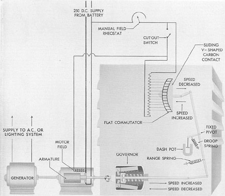
9A1. Automatic motor speed regulator for
d.c.-a.c. motor generator set. In order to
maintain the frequency of the a.c. output of the
d.c.-a.c. motor generator set within closely
controlled limits, a speed regulator for the
d.c. motor is required. The speed regulator
is essentially an automatic, mechanical,
governor-operated field rheostat. Its principal
elements
are a mechanical governor which acts as the
sensitive element, and a field rheostat which is
in series with the shunt field of the motor to be
controlled.
The governor is coupled to the motor shaft
and consists of balanced weights or flyballs,
rotating about a common shaft. These weights are
prevented from flying outward by pressure of
the governor spring. As the speed of the motor
increases, the pressure of the governor spring is
overcome and the flyballs move outward until a
balanced condition is again reached between
the spring pressure and flyballs. The outward
motion of the flyballs and the movement of the
governor spring actuate an operating rod which
in turn transmits its motion, through a lever
and bracket, to the sliding contact bar of the
regulator field rheostat.
The field rheostat is of segment assembly
(commutator) design. The segments are
electrically connected to resistor plates. As the
V-shaped carbon contact bar is moved across
the segments, the resistance included between
the two points of the V contacting the segments
is short circuited, thereby increasing or
decreasing the strength of the motor shunt
field, depending upon the direction in which
the contact
bar is moved.
The speed at which the regulator operates
is principally dependent upon the tension setting
of the governor spring. This setting, how
ever, cannot be sufficiently accurate to operate
the regulator within the desired regulation
motor speed. To provide a finer adjustment, a
range spring that permits adjustment to within
5 percent of normal speed is connected to the
actuating lever. This spring, due to its length
and the location of its pivot pin, aids the action
of the governor spring. It does not, however,
exert enough force to interfere with the movement
of the flyballs. Normally, the range spring
should be set halfway between zero and maximum
tension; and further adjustment, to obtain
normal motor speed, should be made at the governor
control spring.
To reduce hunting and provide stability to
the operation of the regulator, an oil dashpot
and a droop spring are coupled to the actuating
lever. The dashpot consists of an oil-filled
cylinder in which a piston operates. It is coupled
to the actuating lever by means of a piece of
flat spring steel. Whenever the actuating lever
moves, the flat spring forces the piston to move,
and since the oil tends to retard this movement,
the tendency of the actuating lever to hunt is
appreciably reduced.
The droop spring is attached to the actuating
lever by means of a bracket. The position of
the bracket and droop spring in relation to the
actuating lever is such that the tension in the
spring opposes the tension provided by the governor
spring with a varying force, dependent
upon the position of the actuating lever. A
similar effect would be obtained if the droop spring
were omitted, and the governor spring tapered
(conical) in cross section. This is the case in
many types of governors.
Regulator adjustments should be attempted
only after a thorough study of the manufacturer's
instruction book which outlines the correct
procedures to be followed.
This regulator is shown mounted on the
motor shaft on a motor generator set in Figure
9-1.
124
This type of governor is also used to regulate
the speed of the d.c.-d.c. motor generators
used for lighting on some vessels. Speed regulation
in this case is used to control the voltage
regulation and it becomes therefore a voltage
regulator as well.
9A2. Operation. Prior to starting the motor
generator set, the operator should make certain
that the manual motor field rheostat is at the
lowest speed (all resistance cut out), and that
the manual generator field rheostat is at the
lowest voltage end (all resistances cut in), also
that the automatic speed and voltage regulator
switches are in the OFF position. The motor
generator set should then be started and the
speed of the set increased, using the manual
motor field rheostat, until the frequency of the
a.c. output voltage is approximately 62 cycles.
The automatic speed regulator switch should
then be put in the ON position. This places the
automatic, speed regulator in operation. The
manual motor field rheostat should now be returned
to the lowest speed position.
In stopping, the load should first be removed
from the generator, and the automatic speed
regulator switch then turned to the OFF position.
9A3. Maintenance. Moving parts of the
Figure 9-1. Speed regulator for lighting motor generator sets and interior communication a.c. motor generator sets.
125
regulator should be kept free and clean. The contact
bar and the contact surface of the segment
assembly should be inspected periodically. If
the regulator has remained idle for any length
of time, or if the contact surfaces have become
rough for any reason, polish these surfaces. Use
very fine sandpaper (8/0) and finish with crocus
cloth. If the contact surfaces are so rough that
the sandpaper alone will not produce a smooth
finish, use a very fine file such as a contact point
file, follow up with a fine-grade sharpening
stone, and then finish with sandpaper and crocus
cloth. The contact surface across the segments
must be kept absolutely straight. Care should
also be taken not to burr the segments while
polishing, and no particles should remain in the
undercut sections between adjacent segments.
Neither the contact bar nor the segment assembly
should ever be oiled.
In the event that it becomes necessary to
renew any parts of the regulator that might
disturb its operating adjustment, the manufacturer's
instruction pamphlet should be studied carefully
and the adjustment procedure outlined
therein followed precisely.
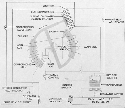
B. ROTARY SOLENOID TYPE AUTOMATIC A.C. VOLTAGE REGULATOR
9B1. Description. In order to maintain a
constant a.c. line voltage in the output of the
a.c. generator, a voltage regulator is required.
The rotary solenoid type regulator is essentially
a solenoid-operated, sliding contact, field rheostat.
It consists principally of a sensitive rotary
solenoid with a spring balanced plunger, a
transformer, a dry disk rectifier, and a field
rheostat which is in series with the shunt field
of the a.c. generator whose voltage is to be
controlled.
The rotary solenoid is energized by means
of rectified current obtained from the generator
through the transformer and rectifier. The
plunger of the solenoid controls the excitation
of the generator field by moving a V-shaped
sliding contact bar across segments which are
connected to the voltage regulator resistors. As
the V-shaped contact bar is moved across the
segments, the resistance between the two points
of the V making contact is short circuited,
thereby increasing or decreasing the strength of
the generator shunt field, depending upon the
direction in which the contact bar is moved.
Any change in the generator a.c. voltage
causes a variation in the magnetic field strength
of the solenoid and this in turn causes the
solenoid plunger to move the sliding contact bar. At
the normal voltage output of the generator, the
magnetic field is of such strength as is necessary
to keep the plunger approximately in midposition.
A spring is attached to the plunger arm.
When the circuit is deenergized this spring keeps
the plunger in its maximum clockwise position.
When the circuit is energized, the magnetic field
of the solenoid tends to move the plunger in a
counterclockwise direction, putting the spring
under tension. The spring tension, however, is
adjusted so that at normal voltage, or midposition
of the plunger, a balanced condition is
attained between the tension of the spring and
the strength of the solenoid magnetic field.
In the event that the a.c. voltage decreases
in the circuit, the following action takes place:
1. The magnetic strength of the solenoid
is decreased, allowing the spring to pull the
plunger in a clockwise direction.
2. As the plunger moves in a clockwise
direction, more resistance is shorted out of the
generator field circuit. This increases the generator
field strength and raises the voltage.
If, on
the other hand, the load voltage rises,
an action opposite to that described above takes
place.
To reduce hunting in the system, two features are
installed. One is a sealed oil dashpot
arrangement mounted so that its piston retards
any rotary motion of the plunger arm. The
other is an electrical circuit consisting
of an adjustable resistor so connected across
the solenoid
main winding that the direction of current
through the circuit opposes that of the current
supplied by the dry disk rectifier. Whenever the
terminal voltage of the generator suddenly decreases,
the potential across this circuit is momentarily
decreased, reducing the effect of the
anti-hunt current opposing the main current.
126
This results in a less sudden reduction in the
strength of the magnetic field of the solenoid
than would be obtained if the anti-hunt circuit
were not installed. Therefore, the effect of the
circuit is to retard any sudden tendency of the
plunger to move in a clockwise direction. If the
terminal voltage of the generator suddenly increases,
the effect of the anti-hunt circuit is to
retard the sudden movement of the plunger in
a counterclockwise direction.
In addition to the main winding on the
solenoid, there is a compound winding. This
winding carries a portion of the generator field
current and is connected so that its magnetic
effect opposes that of the main winding,
resulting in a compounding effect. A bypass resistor
is connected across the winding to serve as a
means of adjusting the amount of compounding.
The range of voltage through which the
regulator must operate is controlled by
adjustment of the range control resistor.
To attain
approximately normal voltage, the initial
adjustment of the range control resistor should be
made with the regulator control rheostat in
midposition. Final adjustment is then made by
positioning the control rheostat.
It is to be noted that the tap on the secondary
of the transformer is deliberately made
off-center in order to introduce a slight unbalance
of the magnetic field of the solenoid in operation
and thus reduce the effect of static friction on the
plunger.
Figure 9-2. Schematic diagram of I.C. motor generator voltage regulator, rotary solenoid type.
127
9B2. Operation. After the motor generator
set has been started and the frequency of the
a.c. voltage regulated as outlined in Section 9A2,
the output voltage of the generator should be
manually adjusted to its rated value by means
of the generator field rheostat. Then, with the
automatic regulator control rheostat set
approximately in its midposition, the regulator
switch
should be turned on and the manual generator
field rheostat turned to the ALL RESISTANCE
OUT position. The regulator now has control
of the voltage and final readjustment of the
voltage can be made by means of the regulator
control rheostat.
In removing the regulator from control of
the generator, the load should first be removed
from the generator. The manual generator field
rheostat should next be moved to cut all resistance
into the generator. The automatic regulator switch
may then be turned to OFF.
9B3. Maintenance. The same general procedures as
outlined in Section 9A3 should be followed in
maintaining this voltage regulator.
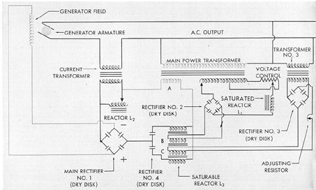
C. REACTOR TYPE AUTOMATIC VOLTAGE REGULATOR
9C1. Description. A reactor type automatic
voltage regulator is essentially a series of
electrical and magnetic circuits so connected that
they automatically control the field current of
the a.c. generator to maintain a constant line
voltage in the output circuit of the a.c. generator.
It consists principally of a number of reactors,
transformers, and rectifiers. A schematic
diagram of this regulator is shown in Figure
9-3. For simplification the relays and controls
are not shown.
When the voltage regulator is not energized,
the a.c. voltage can be controlled manually
by the generator field rheostat. To put the
regulator in operation, the voltage regulator
switch is closed. This supplies power to the main
power transformer and, through relays, transfers
generator field control to the voltage regulator.
The main rectifier, No. 1, is supplied from
the winding A on the main power transformer,
and from the current transformer. The reactor
L2 is connected across the current transformer
so that the voltage supplied by this unit will
have proper phase relationship to the voltage
supplied by the main power transformer. This
phase relationship is such that the vector sum of
the voltages across the two units is approximately
proportional to the field current required by
the generator to maintain constant
voltage, regardless of power factor.
The saturable reactor L3 is connected in
series with the main rectifier supply, and
its impedance is automatically adjusted to maintain
the exact field current required to produce constant
voltage. The impedance of the saturable
reactor is controlled by the two d.c. exciting
coils, B and C. Under normal operation, the
magnetizing forces provided by these two coils
are approximately equal but in opposite directions.
The current in coil C, which tends to saturate
the reactor, is supplied by transformer
No. 3 and rectifier No. 3, and is proportional to
the output voltage of the generator. The current
in coil B tends to reduce the saturation of the
reactor and is supplied by rectifier No. 2. The
power for this rectifier is supplied by the main
power transformer windings and is controlled
by the saturated reactor L1 and the voltage
control.
Since reactor L1 is saturated, a small change
in the voltage supplied to the circuit causes a
relatively large change in the current flowing
through the rectifier and through the reactor coil
B. By adjusting the voltage control and the tap
on the main power transformer winding, the
ratio between the load voltage and the voltage
supplied to the reactor L1 can be varied.
Coil B is used to control the degree of saturation
in the reactor L3. Coil C is used to provide a base
magnetizing force so that the total
magnetizing force will be extremely low. This
is done because reactor L3 is most sensitive to a
change in magnetizing force when the total magnetizing
force is nearly zero.
In operation, the voltage control is set so
that the load voltage is of the desired magnitude.
If the load voltage becomes momentarily
too large, the current through reactor L1 is
128
increased greatly, and the d.c. winding B reduces
the saturation of the saturable reactor. This
increases its impedance and thus reduces the field
current supplied to the generator, returning the
load voltage to its normal value. If the load
voltage becomes momentarily too low, the current
in reactor L1 decreases greatly, and the
load voltage is brought up to its normal value
in a similar manner.
When a load is applied to the generator, the
increased current in the current transformer
supplies a greater voltage to rectifier No. 1, thus
instantly increasing the field voltage to the value
required to maintain constant load voltage.
When the load is decreased, the opposite occurs.
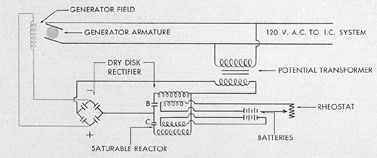
To clarify the operating principle of the
saturable reactor, Figure 9-4 shows rectifiers No.
2 and No. 3 of Figure 9-3 replaced by batteries.
Coil C of the saturable reactor receives a constant
potential from one of the batteries while
a rheostat inserted in the battery circuit
supplying coil B permits voltage to that coil to be
varied. Variation of the voltage in coil B controls
the impedance of the saturable reactor and
this in turn regulates the generator field through
the main rectifier. The rheostat in the circuit of
coil B takes the place of the saturable reactor
L1 and the voltage control shown in Figure 9-3.
9C2. Operation. The operating procedure
for this voltage regulator is the same as that
given for the rotary solenoid type described in
Section 9B2.
9C3. Maintenance. The only parts of this
regulator that require maintenance are the relays,
which are located on the control panel.
Contact burning is kept at a minimum by having
the relays electrically interlocked to prevent
arcing. The contacts are of pure silver and are
not affected by blackening. However, if the
points become badly pitted, they should be
dressed with a fine point file or replaced. The
contact gap should be set between 1/8-in. and
3/16-in. The relay bearings should be kept free
from dirt to insure satisfactory operation.
The manufacturer's instructions should be
studied and followed in replacing or adjusting
any parts of the regulator that may require
such service.
Figure 9-3. Schematic diagram of I.C. motor generator voltage regulator, reactor type.
129
Figure 9-4. Equivalent schematic diagram of I.C. motor generator voltage regulator, reactor type.