MAIN GENERATORS AND MOTORS
AND AUXILIARY GENERATOR
A. PROPULSION
2A1. Description. The propellers of a modern
submarine are driven by four main motors
(see Figure 2-1.) arranged in pairs to drive each
propeller shaft through a reduction gear, or by
two double armature main motors which are
coupled directly to and operate in the speed
range of the propellers.
Each gear unit used in a gear drive installation
is a single reduction, double helical type
designed to reduce the main motor speed of
approximately 1300 revolutions per minute
(rpm) to the propeller speed of 280 rpm.
Power for driving the main motors is obtained
from one of two sources: the four main
generators driven by the main diesel engines;
or, for submerged operation, the main storage
batteries.
A single main generator, or any combination of
the four, may be employed for charging
the main storage, batteries.
The auxiliary generator, driven by the
auxiliary diesel engine, serves several purposes. It
supplies current 1) for all auxiliary circuits,
relieving the battery of the auxiliary load; 2) for
charging the batteries at a low rate; and 3) for
driving the main motors at slow speed through
the main storage batteries.
Control of main propulsion machinery is
accomplished through the main propulsion
control equipment, or control cubicle, located in
the maneuvering room.
Detailed descriptions and instructions for
the care and maintenance of the various components
and their related controls are given in
the chapter dealing with each specific component.
2A2. Manufacturers of main propulsion
equipment. Main motors, main generators,
and auxiliary generators are produced for and
furnished to the Navy by the following
manufacturers: General Electric, Allis-Chalmers,
Elliott, and Westinghouse.
Main control cubicles are manufactured by
General Electric, Cutler-Hammer, and
Westinghouse. Installations are usually paired as
follows: General Electric motors, generators, and
controls; Westinghouse motors, generators, and
controls; Allis-Chalmers motors and generators
and Cutler-Hammer controls; Elliott motors and
generators and Westinghouse controls.
Some of the differences that exist in electrical
and structural design of equipment produced by
these manufacturers are illustrated
and described in this and the following chapters.
B. MAIN AND AUXILIARY GENERATORS
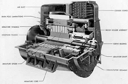
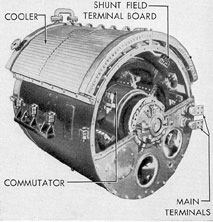
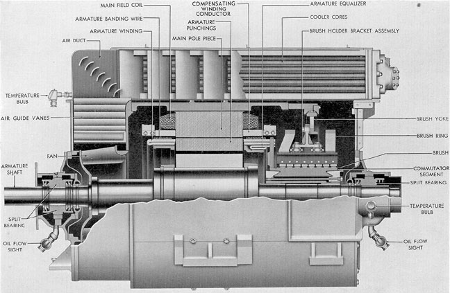
2B1. Description of main generators. The
following terms describe the characteristics of
main generators: two wire, direct current, separately
excited, shunt wound, compensated
multipolar, totally enclosed, and self ventilated.
The armature shafts for generators used with
General Motors engines are supported at each
end on a bearing; those used with Fairbanks-Morse
engines are so supported only at the commutator end.
The bearings are force-lubricated
by the oil supply from the main engine lubricating system.
The maximum speed of a main generator
varies with the type of main engine. Maximum
speed with a General Motors engine as a prime
mover is 750 rpm; with a Fairbanks-Morse engine,
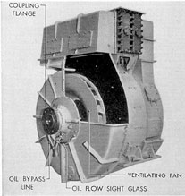
720 rpm. Direct flexible coupling to the
engine is accomplished through the flanged end
of the generator armature shaft.
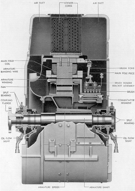
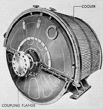
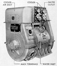
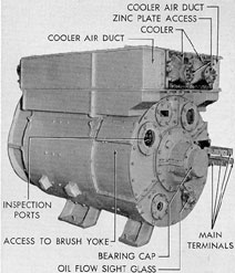
Figure 2-3. Cutaway of Westinghouse main generator.
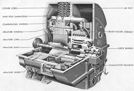
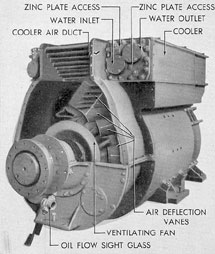
Figure 2-4. Cutaway of Elliott main generator cooling unit.
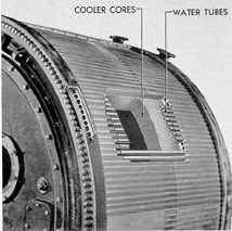
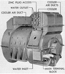
Figure 2-5. Cutaway of Allis-Chalmers main generator cooling unit.
18
Allis-Chalmers machines, the construction of all
main and auxiliary generators is similar. The
Main generators are rated at approximately 2650
amperes at 415 volts and 1100 kilowatts.
Detailed ratings and characteristics of the
various machines are found in the individual
manufacturer's instruction books.
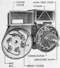
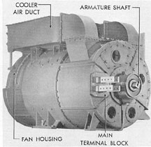
Figure 2-6. Commutator end view of G.E. main generator.
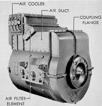
Figure 2-7. Coupling end view of G.E. main generator section cover removed.
External views of various types of submarine
propulsion generators are shown in Figures
2-2 through 2-10.
Figure 2-8. Commutator end view of Elliott main generator.
Figure 2-9. Commutator end view of Elliott main generator With front end bell removed.
19
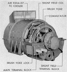
Figure 2-10. Coupling end view of Allis-Chalmers main generator.
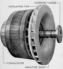
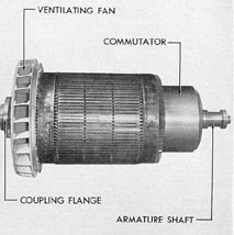
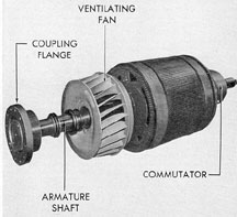
2B2. Armature. The armature shaft is a
single piece of forged steel. Coupling flanges,
thrust collars, and oil deflectors are part of the
shaft.
A spider for supporting the armature laminations
is shrunk and keyed to the shaft. The
core of the armature consists of magnetic steel
punchings assembled in a group and secured to
the spider by means of a shrink fit and keys.
After the punchings are in position, a flange is
pressed into place and held by circular keys.
2B3. Armature windings. Armature windings consist
of a number of single turn coils.
These coils are placed in slots on the armature
and held in place by slot wedges. The ends of
the coils outside the slots are held by nonmagnetic
steel banding wire. The windings are insulated
from their supporting flanges by pieces
of mica. An equalizer winding is provided in all
submarine generators. It consists of connections
between points of equal voltage in the armature
circuit for balancing the current in the various
armature circuits. It is usually located at the
commutator end of the machine in a recess provided
in the flanged portion of the spider. It is
insulated from other parts by layers of mica.
2B4. Commutator. The commutator consists
of copper segments insulated from each other by
mica, and held in position by V-shaped clamping rings.
Mica is also used to insulate the segments from the
clamping rings. The clamping
rings are supported by through bolts or clamping studs,
which, when tightened, hold the segments securely in
position. The adjustment of
these through bolts should never be changed.
Figure 2-11, Coupling end view of G.E. main generator armature.
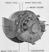
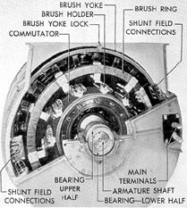
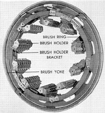
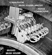
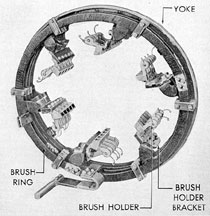
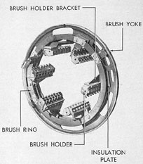
2B5. Brush rigging and brush holders. The
brush rigging consists of a circular steel yoke to
which the brush holder assemblies are attached.
Some types of yokes have gear teeth cut around
the outer periphery and meshed with a removable
pinion for rotating the rigging. Other types
have holes drilled around the outer periphery
into which a lever can be inserted to accomplish
the same purpose.
Each brush holder is attached to a bracket
which is secured to, but insulated from, the steel
brush yoke. The brush holders contain brushes
arranged two in a holder on each bracket. On
General Electric and Elliott generators, one of
the brushes in each holder runs with a leading
angle and the other with a trailing angle. On
Westinghouse and Allis-Chalmers generators,
both brushes have a leading angle.
The complete brush rigging assembly is attached
to the generator field frame and locked
in position by clamps or studs. Access to the
brush rigging lock is obtained by removing
20
inspection cover plates located on the side of the
machine.
Figure 2-12. Commutator end of G.E. main generator, with cooler, end bell, and upper half of bearing housing removed.
Figure 2-13. Main generator brush rigging.
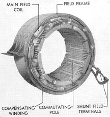
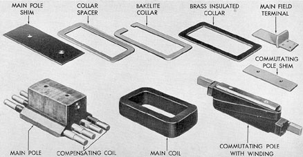
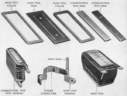
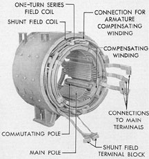
2B6. Main field poles and coils. Each main
field pole consists of a number of steel
laminations riveted together and bolted to the frame.
Each lamination has slots punched near the
pole face to provide for insertion of the
compensating windings (see Section 1E12). Shims between
the poles and the frame permit adjustment of the air gap.
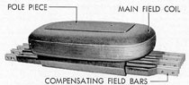
The main field coils are wound around, but
insulated from, the pole piece body. All coil
leads for each half of the field are carried to
terminal blocks located inside the machine. Any
disabled coil may be cut out of the circuit at
these terminal blocks.
Figure 2-14. Brush holder and bracket.
Figure 2-15. Main generator field frame and windings.
21
2B7. Commutating field poles and coils.
The commutating field poles (see Section lEll)
are made either of laminated or solid steel plate
and are bolted to the frame. There are magnetic
and nonmagnetic shims between the pole piece
and the frame for adjusting the air gap and
strength of the commutating fields. The coil
consists of several turns of solid copper bus bar
fastened to the pole piece by means of insulated
steel studs.
2B8. Compensating winding. The compensating winding
(see Section lE12) consists of
copper bars inserted in slots in the main pole
pieces. The winding elements are insulated from
the pole by mica and joined by copper bars
bolted in place.
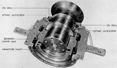
the commutator end are lined with soft metal
to take the thrust load.
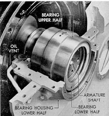
Escape of oil from the housing is prevented
by deflector rings on the armature shaft and by
oil seals in each inner half of the bearing housing.
An air chamber around the shaft at the inside
end of the bearing housing is vented by
pipes to the outside of the machine. This prevents the formation of a vacuum around the
shaft and provides a drain for any possible oil
leakage before it reaches the interior of the
machine.
The bearing is drained through a pipe
equipped with an oil flow sight. To prevent an
excessive flow of oil from reaching the bearing,
Figure 2-16. Miscellaneous field parts, Allis-Chalmers.
2B9. Terminals. The armature terminals are
brought out through a terminal board. These
terminals are silver plated to obtain low contact
resistance.
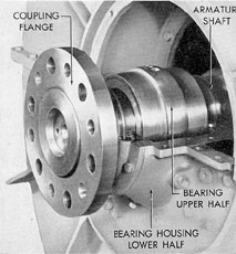
2B10. Bearing and bearing lubrication. The
bearing consists of a split shell, lined with soft
metal, usually babbitt. It is carried in a split
housing which is in turn bolted to the frame of
the machine. The two halves of the bearing shell
are accurately aligned by two dowel pins, one
on each side. The ends of the bearing shells at
and also to allow the use of openings in the
feed line of not less than 3/16-in. diameter, some
of the oil is bypassed around the bearing. Pressure
at the inlet to the bypass chamber should
be 10 to 15 pounds per square inch.
In order to remove the upper half of the
bearing housing, it is necessary on some
machines to remove an adapter plate first, thus
providing sufficient clearance for lifting the
bearing housing over the bearing. Lifting
jackscrews are provided, which, when turned, lift
22
Figure 2-17. Lower half of main generator bearing installed.
the shaft slightly and permit rotation of the
lower half of the bearing to the top of the shaft
for removal (see Section 7A12). Serious casualties
have been caused by failure of repair personnel
to lower the jack after replacing a bearing.
Figure 2-18. Main generator bearing, coupling end.
Figure 2-19. Main generator bearing, commutator end.
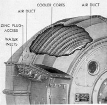
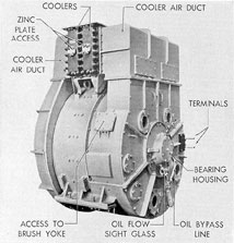
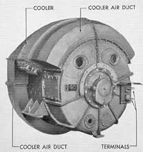
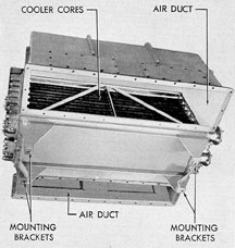
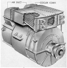
2B11. Cooling systems. The cooling systems
of all the various machines operate on the same
principle. The hot air is cooled by forcing it
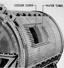
through water-cooled cores, The Allis-Chalmers
machines, however, do not employ the ductwork
23
used on the other makes of machines (see
Figure 2-5). The cooling unit on these generators
fits the contour of the machine and is made in
two sections, each half-section covering one
fourth of the outer surface of the generator.
Water tubes are set in grooves on the outer
surface of the shell to absorb the heat from
the circulating air.
The other makes of machines have the
water tubes mounted in cores, similar to an
automobile radiator. This assembly is located
in the air ducts of the cooling system through
which the air passes.
Circulation of air is effected by the ventilating
fan attached to the armature shafts. Air is
delivered from the cooler into the commutator
end housing. It is then drawn through the field
coils and through the commutator ends, under
the commutator into the armature, and then
through ventilating ducts in the armature core.
On Westinghouse generators the fan is located
on the commutator end and the air flow is thus
reversed.
Figure 2-20. Bottom view of G.E. main generator cooling unit.
Figure 2-21. Cutaway of Westinghouse auxiliary generator.
24
The coolers are designed to deliver air at
104 degrees F to the windings. The air entering the
coolers may vary in temperature, depending on
the type of machine. The manufacturer's
instruction books give the maximum allowable
temperatures of the air from the windings.
2B12. Description of the auxiliary generator.
The 300-kw direct current auxiliary generator
Is a two-wire, compensated, differential
compound machine. The generator is self-excited,
but the switching is arranged so that
separate excitation may be obtained from the
battery. The machines can produce 300 kw at
1200 rpm at any voltage from 260 volts to
345 volts, and 150 kw at 600 rpm at 260 volts.
The generator is connected to the auxiliary
Diesel engine through a semirigid coupling. The
commutator end of the armature shaft is supported
on a sleeve bearing which is force-lubricated
from the engine lubricating system. The
opposite end of the shaft is carried by the engine
bearing. The generator armature thrust is
taken by thrust collars on the shaft and thrust
faces on the ends of the sleeve bearing.
In construction, auxiliary generators differ
only in minor detail from the main generators.
They are produced by the same manufacturers
and, with the exception of differences in size,
weight, and number of some of the components,
Figure 2-22. Right front view of G.E. auxiliary generator.
the auxiliary and main generators are identical.
The rating and classification of the auxiliary
generators can be found in the manufacturer's
instruction book furnished with the
equipment. The various makes and some of the
principal components are illustrated in Figures
2-21 through 2-30.
Figure 2-23. Front view of G.E. auxiliary generator, end shield and cooler cover removed.
Figure 2-24. Commutator end view of Elliot auxiliary generator.
25
Figure 2-25. Elliott auxiliary generator, end bell and cooler removed.
Figure 2-26. Commutator end view of Allis-Chalmers auxiliary generator, end cover removed.
Figure 2-27. Later type Allis-Chalmers auxiliary generator.
Figure 2-28. Armature for G.E. auxiliary generator.
Figure 2-30. Miscellaneous field parts, Allis-Chalmers auxiliary generator.
27
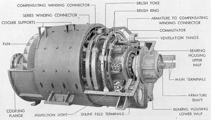
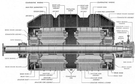
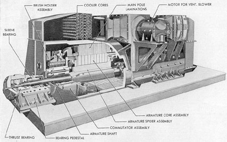
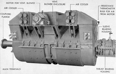
Figure 2-31. Cross section of G.E. main motor.
28
C. MAIN MOTORS
2C1. Description of geared main motors.
The geared type main motors are of the two-wire,
d.c., compound type with shunt, series,
commutating, and compensating field windings.
Separate excitation for the shunt field is
provided by the excitation bus which receives power
from either battery.
The motors are totally enclosed, watertight
below the field frame split and waterproof
above. Cooling is accomplished by a fan which
is attached to the armature shaft and circulates
the air through cores cooled by circulating water.
Each end of the armature shaft is supported
on a split sleeve bearing. The bearings
are lubricated from the oil supply in the
reduction gear units.
Various combinations of armatures in series
or in parallel, including the coupling of all
four motors in series for dead slow operation,
may be obtained, for either surface or submerged
operation, through the main control
cubicle.
For surface operation, motor speed control
is accomplished by controlling the generator
speed and shunt field, thus varying the voltage
supplied. When submerged, speed is controlled
Figure 2-32. Cutaway of Elliott main motor cooler section.
by varying the motor shunt field or by connecting
the motors in different combinations of series
and parallel. Reverse operation is accomplished
by reversing the direction of the flow of
current in the motor armature circuit.
Figure 2-33. Cutaway of Allis-Chalmers main motor cooler section.
Figure 2-34. Commutator end view of G.E. main motor.
29
Figure 2-35. Coupling end view of G.E. main motor, flat cover plate and air duct cover removed.
Main motors used in a gear drive installation
are classed as high-speed motors and each
is rated for continuous duty at approximately
1370 hp, 415 volts, 2600 amperes, and 1300 rpm.
Figure 2-36. Commutator end view of Elliott main motor.
Figure 2-37. Elliott main motor with end bells removed.
30
2C2. Commutator, armature, armature windings,
brush rigging, brush holders, field frame,
and windings. Figures 2-38 through 2-42 illustrate
these parts. They are practically identical
in construction with the corresponding parts
of a main generator. For their description, see
Section 2B.
Figure 2-38. Coupling end view of G.E. main motor armature.
Figure 2-39. Main motor brush rigging.
Figure 2-40. Main motor field frame and windings.
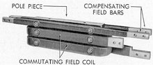
Figure 2-41. Main coil on pole piece with compensating field bars.
Figure 2-42. Commutating field toil on pole piece with compensating field bars.
2C3. Bearings. As in the main generators,
the armature shaft of a main motor is supported
on a split sleeve with a spherical or cylindrical
seated bearing at each end. The two halves of
the bearing are held together between two
halves of the bearing housings which are
clamped together and bolted to the bearing
brackets. End clearance at the commutator end
is large enough to make certain that the thrust
31
load will be taken by the coupling end bearing
only. Each bearing is sealed against oil leakage
by deflector rings and oil seals. The bearing
temperatures are measured by Brown resistance
temperature units, the detectors of the units
being located in the lower halves of the bearings.
The maximum safe operating temperature of
the bearings is 180 degrees F.
2C4. Lubrication. Oil under pressure is supplied
to the motor bearings by a gear-driven
lubricating oil pump which is attached to the
reduction gear units of each pair of motors.
However, when the propeller shaft speed is below
38 rpm, a standby pump which supplies sufficient
oil pressure both for reduction gears and
main motor bearings is placed in operation.
Oil catching grooves and return drains in the
housing prevent leakage of oil along the shaft into
the windings. An air chamber between the bearing
and the interior of the motor serves to prevent
the formation of a vacuum around the
shaft and permits drainage of any possible oil
leakage before it reaches the interior of the
motor. A safety overflow is provided in the
housing oil reservoir to prevent possible flooding of
the winding if the drain should become clogged.
After passing through the bearing, the oil passes
out of the housing through a sight flow and returns
to the lubricating oil sump. When the
flow of oil at the sight flow glass appears to be
appreciably reduced or, if the oil pressure falls
below 5 psi, the standby pump must be placed
in operation. The standby system is also used
to force lubricant to the bearings before starting
the motors after a shutdown period.
2C5. Cooling systems. The main motor
cooling units are similar to the main generator
units with one exception. The Allis-Chalmers
cooling units on the main motor are constructed
in three sections and cover approximately 90
percent of the outer surface of the motor frame.
The remaining surface is covered with a dummy
section to secure the necessary clearance for the
motor arrangement in the motor room. The arrangement
is such that each motor has its cooler
sections placed on different portions of its outer
surface.
2C6. Description of double armature
propulsion motor. a. General. On the latest
classes of submarines, main motors and
reduction gears have been replaced by two 2700-hp
double armature motors, directly connected to
the propeller shafts, one to the starboard, the
other to the port shaft.
The motors are of the two-wire, d.c., compound,
compensated type with shunt and series
field windings and commutating poles. Separate
excitation for shunt fields is provided by the
excitation bus which receives power directly
from the battery buses in the control cubicle.
The motors are totally enclosed and a water
tube air cooler is mounted crosswise over the
motor frame. Mechanical air filters are located in
the air ducts between the coolers and vent
blower. A separate motor-driven fan circulates
the cooling air. When the motors are operating
in the SLOW position, neither cooling air nor
circulating water is required. The motor for the
ventilation fans normally is connected across
the terminals of one of the propulsion motor
armatures. When the bus selector lever is in the
SLOW position, this connection is opened.
If at any time it becomes necessary to disconnect
the propulsion motor armature to which
the vent blower is normally connected, and still
operate the other propulsion motor armature,
the vent motor connections can be shifted to the
armature intended for operation by means of
connector links provided in the vent motor leads
in the control cubicle.
The motor frame is split at an angle of
approximately 11 degrees from the horizontal
centerline to permit easy removal of the armature.
The motor is watertight below this joint
and waterproof above.
The armature is mounted on a hollow
forged steel shaft which is flanged at the after
end for coupling to the propeller shaft. Each end
of the shaft has a bearing journal for a force-lubricated,
split sleeve bearing mounted in a
pedestal separate from the frame. In addition
to the radial bearing, the forward end of the
shaft is fitted with a collar for a Kingsbury
thrust bearing which takes the propeller and
motor thrust load.
To secure proper compensating field
strength over the entire operating range, the
compensating winding of each motor is shunted
by a permanent resistor which is adjusted to
give good commutation over the entire range.
32
Figure 2-43. Cross section of Elliott double armature propulsion motor.
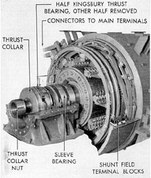
Figure 2-44. Cutaway of Westinghouse double armature propulsion motor.
33
Figure 2-45. Double armature propulsion motor.
b. Operation. For surface operation, using
the various combinations of armatures and
taking power from the main generators, the motors
develop from 20 hp to 2700 hp per propeller
shaft at speeds ranging from approximately 67
rpm to 282 rpm.
For submerged operation, using various
combinations of armatures and taking power
from the batteries, the motors develop power
ranging from 30 hp to 1719 hp per propeller
shaft and give a speed range from 38 rpm to 219
rpm.
c. Motor frame. The motor frame is constructed
in two halves which are doweled together.
Jackscrews in the supporting feet assist
in shimming and properly aligning the frame.
The frame and enclosures are watertight below
the frame split and waterproof above. Any
condensate or liquid from other sources that may
find its way into the interior of the motor will
drain into the bottom of the end enclosures or
center section and may be drained off from there
with a hand pump. Steel brackets are bolted
and doweled to the frame sections for support
of the brush rigging. Removable plates provide
access to the connections.
d. Bearings. The radial bearing sleeves
are carried in split cast steel pedestals. These
are bolted to the motor bedplate which is welded
to the hull. The caps of the bearing pedestals
are held in position by fitted studs.
Bearing sleeves are made of cast steel lined
with babbitt. They are machined to fit the
spherical seat in the bearing pedestal and are
secured against rotation by a dowel pin in the
pedestal cap. The babbitt on the sides of the
sleeves is cut away slightly to allow proper
distribution of oil. Grooves through the sides of the
sleeves at the horizontal split permit a
circulation of oil in addition to that which passes under
34
Figure 2-46. Double armature propulsion motor with enclosures removed.
the shaft. This extra flow of oil passing over
the shaft journal carries away heat and also
tends to prevent collection of sludge in the bearings.
A jacking beam is provided in the lower
housing to support the shaft while removing
bearing sleeves. The bearing pedestals and
sleeves are drilled to permit the use of a depth
gage for measuring bearing wear. A bridge gage
may also be used for measuring bearing wear
or to locate properly a new bearing shell.
The Kingsbury thrust bearing on the forward
end of the shaft takes the thrust load of
the propeller and motor in both ahead and
astern directions. The bearing consists of
a rotating collar keyed to the shaft, and stationary
shoes with load-equalizing supports or leveling
plates which allow for slight misalignment.
e. Lubrication. Oil is supplied to the
bearings by a separate motor-driven lubricating
oil pump for each shaft. Oil-catching grooves
and felt wipers in the housing prevent leakage
of oil along the shaft. After passing through the
bearing, the oil passes out of the housing through
a sight flow and returns to the sump tank.
A resistance type temperature detector for
indicating bearing temperature is located in the
lower half of each radial bearing and in the discharge
oil from the Kingsbury thrust bearing.
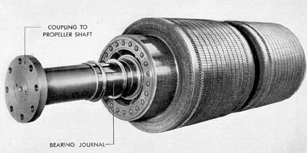
f. Armature shaft. Except in Westinghouse motors,
the armature shaft is a one-piece
Figure 2-47. Propulsion motor double armature, coupling end.
35
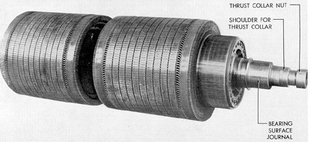
Figure 2-48. Propulsion motor double armature, thrust bearing end.
steel forging machined to proper fit for support
of two armatures and their commutators.
Westinghouse motors have two-piece shafts coupled
together in the center. Three oil throwing
collars are machined on the shaft one on each side
of the bearing journal at the coupling end, and
one on the forward end of the shaft.
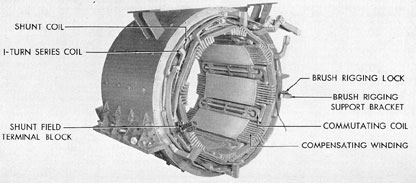
g. Armature core, armature winding,
commutators, brush rigging, brush holders, and field
windings. With the exception of minor details,
the construction of these components is similar
to that of the corresponding parts of a high-speed
main motor or generator. The field frame
and windings are illustrated in Figure 2-49. For
specific details refer to the manufacturer's
instruction book furnished with the equipment.
Figure 2-49. Double armature propulsion motor field frame and windings.
36
D. CABLES
2D1. General. Each of the various types of
electrical cables used on submarines has a
certain number of conductors and a type of
insulation designed for a specific application. Each
type and size has a definite rating with respect
the maximum operating voltage for which
it is designed, the maximum load in amperes to
Cables are identified as to type by letters followed
by a number that indicates for
power cables the size in circular mils. For interior
communication and fire control cables,
the number indicates the number of conductors
or pairs of conductors. For example, the designation
SHFL-800 identifies a single conductor,
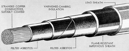
Figure 2-50. Type SHFL single conductor heat and flame resistant leaded cable.
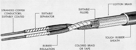
Figure 2-51. Type DCP double conductor portable cable.
be carried under specified conditions, the maximum
extremes of temperature to which the cable
would normally be exposed, and its relative resistance
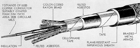
to moisture or flame. The construction
of three types of cables is illustrated in Figures
2-50, 2-51, and 2-52. The labeled parts will be
helpful in understanding the inner composition
of the various cables illustrated.
heat and flame resistant, leaded cable with an
area of approximately 800,000 circular mils. An
MHFA-10 cable is a multiple conductor, heat
and flame resistant, armored cable of 10 conductors.
To facilitate tracing of cable for purposes
of maintenance and replacement, metal tags
stamped with a circuit marking are attached
37
Figure 2-52. Type MHFA multiple conductor beat and flame resistant armored cable.
to the cables (see "How to Read a Cable Tag,"
Section 20D). For specific information on the
routing of a cable run, consult the wiring deck
plan applying to the specific installation.
2D2. Main power cables. The following is
a list of the types and numbers of cables and
their approximate length as used on a few of
the main power circuits. This description is of
a typical installation. Considerable variation will
be found in the various classes of submarines.
1. Forward battery to maneuvering room.
This circuit employs 12 type SHFL-800 cables,
each of which is approximately 150 ft long. In
addition, there is 1 type DHFA-9 ammeter lead,
170 ft long.
2. Auxiliary power distribution switchboard;
circuit run from forward battery to control room.
This circuit employs 4 type SHFL-650 cables,
each of which is 35 ft long, and 1
type SHFA-75 neutral lead of the same length.
3. After battery to maneuvering room.
This circuit employs 8 type SHFL-800 cables,
each of which is approximately 85 ft long, and
1 type DHFA-9 ammeter lead, approximately
110 ft long.
4. Main generators to maneuvering room.
These circuits employ 8 type SHFL-1000 cables,
4 cables for the positive and 4 for the negative
legs. The No. 1 and No. 2 generator cables run
from the forward engine room to the maneuvering
room; the No. 3 and No. 4 generator cables
run from the after engine room to the maneuvering
room. Each of the 8 No. 1 and No. 2
generator cables are approximately 50 ft long. Each
of the 8 No. 3 and No. 4 generator cables are
approximately 15 ft long. Shunt field, ammeter,
and voltmeter cables are type DHFA-4, DHFA-9,
and DHFA-3 respectively.
5. Main motor armature and series field,
positive and negative. The No. 3 and No. 4
main motor circuits employ 16 type SHFL-800
cables for each motor, 4 cables for each armature
leg and 4 cables for each series field leg.
Each cable is approximately 15 ft long. All main
motor shunt field leads are of type DHFA-4
cable, approximately 20 ft long. No. 1 and No. 2
main motors are similarly connected but on
some installations bus bars are used instead of
cables. Each bar or cable is approximately 4 ft
long.
6. Auxiliary generator cable run from aft
engine room to maneuvering room. The positive
and negative leads of this circuit employ 4
type SHFL-650 cables (2 cables per leg), each
of which is approximately 55 ft long.
7. Bus tie to auxiliary power distribution
switchboard. This circuit runs from the
maneuvering room to the control room and employs
4 type SHFL-650 cables (2 cables per leg), each
of which is approximately 150 ft long.
8. Shore connection. This circuit runs
from the after torpedo room to the maneuvering
room and employs 4 type SHFL-650 cables (2
cables per leg), each of which is approximately
45 ft long.