9A1. Combustion. Engine efficiency is a
comparison of the amount of power developed
by an engine to the energy input as measured
by the heating value of the fuel consumed. In
order to understand the various factors responsible for differences in engine efficiency, it is
necessary to have some knowledge of the combustion process which takes place in the engine.
In the diesel engine, ignition of the fuel is
accomplished by the heat of compression alone.
To support combustion, air is required. Approximately 14 pounds of air are required for the
combustion of 1 pound of fuel oil. However, to
insure complete combustion of the fuel, an excess amount of air is always supplied to the cylinders. The ratio of the amount of air supplied
to the quantity of fuel injected during each
power stroke is called the air-fuel ratio and is
an important factor in the operation of any internal-combustion engine. When the engine is
operating at light loads there is a, large excess
of air present, and even when the engine is overloaded, there is an excess of air over the minimum required for complete combustion.
The injected fuel must be divided into
small particles, usually by mechanical atomization, as it is sprayed or injected into the combustion chamber. It is imperative that each of
the small particles be completely surrounded by
sufficient air to effect complete combustion of
the fuel. To accomplish this, the air in the cylinder must be in motion with good fuel atomization, combined with penetration and distribution. In mechanical injection engines this is
accomplished by forcing scavenging air into the
cylinder with a whirling motion to create the
necessary turbulence. This is usually done, in
the 2-cycle engine, by shaping the intake air
ports, or by casting them so that their centers
are slightly tangential to the axis of the cylinder
bore.
Before proceeding with the study of the
combustion process, the conditions considered
essential to good combustion should be reviewed:
1. The fuel must enter the cylinder at the,
proper time. That is, the fuel injection valve
must open and close in correct relation to the
position of the piston.
2. The fuel must enter the cylinder in a
fine mist or fog.
3. The fuel must mix thoroughly with the
air that supports its combustion.
4. Sufficient air must be present to assure
complete combustion.
5. The temperature of compression must
be sufficient to ignite the fuel.
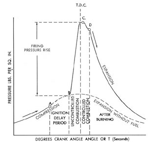
Figure 9-1 is a reproduction of a pressure-time diagram of a mechanical injection engine.
The lower curvy part of which is a dotted line,
is the curve of compression and expansion when
no fuel is injected. At A the injection valve
opens, fuel enters the combustion chamber and
ignition occurs at B. The pressure from A to
B should fall slightly below the compression
curve without fuel due to absorption of heat by
the fuel from the air. The period from A to B
is the ignition delay. From B the pressure rises
rapidly until it reaches a maximum at C. This
maximum, in some instances, may occur at top
dead center. At D the injection valve closes, the
fuel is cut off, but burning of the fuel continues
to some undetermined point along the expansion
stroke.
The height of the diagram from B to C is
called the firing pressure rise and the slope of
the curve between these two points is the rate
at which the fuel is burned.
Poor combustion of the fuel is usually indicated by a smoky exhaust, but some smoke
may be the result of burning lubricating oil that
has passed the rings into the combustion chamber. Incomplete combustion is indicated by
black smoke, or if the fuel is not igniting, it may
appear as blue smoke. Immediately after starting an engine, when running at light loads or at
overloads, or when changing from one load to
another, smoke is likely to appear.
A smoky exhaust from the engine does not
indicate whether one or all the cylinders are
174
Figure 9-1. Pressure-time diagram of combustion process.
causing it A black-smoking cylinder usually
shows a higher exhaust temperature which can
be observed from pyrometers installed in the
individual exhaust lines from the cylinders.
Opening the indicator cock on each cylinder to
observe the color of the exhaust is another
check. Still another method is cutting off the
fuel supply to one cylinder at a time to see what
effect it has on the engine exhaust. This latter
should never be done when the engine is operating at full load as overloading of the other
cylinders will result if the engine is governor
controlled.
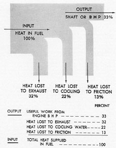
9A2. Engine losses. It is obvious that not all
of the heat content of a fuel can be transferred
into useful work during the combustion process.
The many different losses that take place in the
transformation of heat energy into work may be
divided into two classes, thermodynamic and
mechanical. The net useful work delivered by
an engine is the result obtained by deducting
the total losses from the heat energy input.
Thermodynamic losses are caused by:
1. Loss to the cooling system and losses by
radiation and convection to the surrounding air.
2. Heat rejected and lost to the atmosphere
in the exhaust.
3. Inefficient combustion or lack of perfect
combustion.
A loss due to imperfect or incomplete combustion is an important item, because such losses
have a serious effect on the power that can be
developed in the cylinder as shown by the pressure-volume diagram or indicator card. Complete combustion is not possible in the short
time permitted in modern engine design. However, these losses may be kept to a minimum
if the engine is kept adjusted to the proper
operating condition. Incomplete combustion can
frequently be detected by watching exhaust
temperatures, noting the exhaust color, and being alert for unusual noises in the engine.
Heat energy losses from both the cooling
water systems and lubricating oil system are
always present. Some heat is conducted through
the engine parts and radiated to the atmosphere
or picked up by the surrounding air by convection. The effect of these losses varies according
to the part of the cycle in which they occur. The
175
heat appearing in the jacket cooling water is not
a true measure of cooling loss because this heat
includes:
1. Heat losses to jackets during compression, combustion, and expansion phases of the
working cycle.
2. Heat losses during the exhaust stroke.
3. Heat losses absorbed by the walls of the
exhaust passages.
4. Heat generated by piston friction on
cylinder walls.
Heat losses to the atmosphere through the
exhaust are inevitable because the engine cylinder must be cleared of the still hot exhaust
gases before another fresh air charge can be
introduced and another power stroke begun.
The heat lost to the exhaust is determined by
the temperature within the cylinder when exhaust begins. It depends upon the amount of
fuel injected and the weight of air compressed
within the cylinder. Improper timing of the exhaust valves, whether early or late, will result
in increased heat losses. If early, the valve releases the pressure in the cylinder before all the
available work is obtained; if late, the necessary
amount of air for complete combustion of the
next charge cannot be realized, although a small
amount of additional work may be obtained.
The timing of the exhaust valve is a compromise, the best possible position of opening and
closing being determined by the engine designer. It is essential that the valve be tight and
properly timed in order to maintain the loss to
the exhaust at a minimum. This is also true for
air inlet valve setting on 4-cycle type engines.
If an indicator card is taken of a diesel
engine cylinder, it is possible to calculate the
horsepower developed within the cylinder. This
calculation does not take into account the power
loss resulting from mechanical or friction losses,
as will be discussed later, but it reflects the
actual work produced within the cylinder.
Mechanical losses are of several kinds, not
all of them present in every engine. The sum
total of these mechanical losses deducted from
the indicated horsepower developed in the cylinders will give the brake horsepower finally
delivered as useful work by the engine. These
mechanical or friction losses include bearing
friction, piston and piston ring friction, and
Figure 9-2. Heat balance for a diesel engine.
pumping losses caused by operation of water
pumps, lubricating oil pumps, and scavenging
air blowers, power required to operate valves,
and so forth. Friction losses cannot be eliminated, but they can be kept at a minimum by
maintaining the engine in its best mechanical
condition. Bearings, pistons, and piston rings
should be properly installed and fitted, shafts
must be in alignment, and lubricating and cooling systems should be at their highest operating
efficiency.
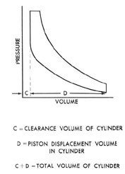
9A3. Compression ratio and efficiencies.
a. Compression ratio. The term compression
ratio is used quite extensively in connection
with engine performance and various types of
efficiencies. It may be defined as the ratio of the
total volume of a cylinder to the clearance
volume of the cylinder. It may be best explained
by reference to the pressure-volume indicator
card of a diesel cylinder. In Figure 9-3, the
volume is reduced from square root(C) + square root(D) to square root(C)
during compression. The compression ratio is
then equal to
(square root(C) + square root(D))/square root(C)
176
Figure 9-3. Compression ratio.
Compression ratio influences the thermal
efficiency of an engine. Theoretically the thermal efficiency increases as the compression ratio
is increased. The minimum value of a diesel engine compression ratio is determined by the
compression required for starting, which, to
large extent is dependent on the type of fuel
used. The maximum value of the compression
ratio is not limited by the fuel used but is
limited by the strength of the parts of the engine and the allowable engine wgt/bhp output.
b. Cycle efficiency. The efficiency of any
cycle is equal to the output divided by the input.
The diesel cycle shows one of the highest efficiencies of any engine yet built because of the
higher compression ratio carried and because of
the fact that combustion starts at a higher temperature. In other words, the heat input is at a
higher average temperature. Theoretically, the
gasoline engine using the Otto or constant volume cycle would be more efficient than the
diesel if it could use compression ratios as high
as the latter.
The gasoline engine operating on the Otto
cycle cannot use a compression ratio comparable to the diesel engine due to the fact that the
fuel and air are drawn in together and compressed. If high compression ratios were used,
the fuel would fire or detonate before the piston
could reach the correct firing position.
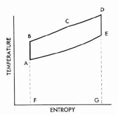
The temperature-entropy (T-S) diagram of
any particular cycle indicates the amount of heat
input and the amount of heat rejected. For example, in Figure 9-4, the T-S diagram of a modified diesel cycle, the heat input is represented by
the area FBDG and the heat rejected to the exhaust by the area FAEG. The heat represented
in doing useful work is represented by the difference between these two, or area ABDE. The
efficiency of the cycle can then be expressed as
(H1-H2)/H1
where H1 is the heat input along lines
BC and CD (the lines representing the constant
volume and constant pressure combustion), and
H2 is the heat rejected along line EA (the line
representing the constant volume exhaust).
Since heat and temperature are proportional to
each other, the cycle efficiency is actually computed from measurements made of the temperature. The specific heat of the mixture in the cylinder is either known or assumed, and when
combined with the temperature, the heat content can be calculated at any instant. Thus, it is
seen that temperature is a measure of heat, and
that the heat is proportional to the temperature
of the gas.
c. Volumetric efficiency. The volumetric
efficiency of an engine is the ratio of the volume
that would be occupied by the air charge at
atmospheric temperature and pressure to the
cylinder displacement (the product of the
Figure 9-4. Temperature-entropy diagram of modified
diesel cycle.
177
area of the bore times the stroke of the piston).
The volumetric efficiency determines the
amount of air available for combustion of the
fuel, and hence influences the maximum power
output of the engine.
Volumetric efficiency is actually the completeness of filling of the cylinder with fresh air
at atmospheric pressure. The volumetric efficiency of an engine may be increased by enlarging the areas of intake and exhaust valves or
ports, and by having all valves properly timed so
that as much air as possible will enter the cylinders. Since any burned gases will reduce the
charge of fresh air, the supercharging effect
gained by early closing of the exhaust valves or
ports will reduce the volumetric efficiency. In
some engines, the volumetric efficiency is also
increased by using special apparatus to utilize
air at 2 to 3 psi over the atmospheric pressure.
This procedure is commonly called supercharging.
d. Thermal efficiency. Thermal efficiency
may be regarded as a measure of the efficiency
and completeness of combustion of the injected
fuel. Thermal efficiencies are generally considered as being of two kinds, indicated thermal
efficiency and over-all thermal efficiency.
If all the potential heat in the fuel were
delivered as work, the thermal efficiency would
be 100 percent. This is not possible in practice,
of course. To determine the values of the above
efficiencies the amount of fuel injected is known,
and from its heating value, or Btu per pound, the
total heat content of the injected fuel can be
found. From the mechanical equivalent of heat
(778 foot-pounds are equal to 1 Btu), the number of foot-pounds of work contained in the fuel
can be computed. If the amount of fuel injected
is measured over a period of time, the rate at
which the heat is put into the engine can be converted into potential power. Then, if the indicated horsepower developed by the engine is
calculated as previously explained, the indicated
thermal efficiency can be computed.
Indicated thermal efficiency =
(Indicated hp X 42.42 Btu per minute per hp) / (Rate of heat input of fuel in Btu per minute) X 100 percent
In like manner the over-all thermal efficiency can be found from the brake horsepower
or the actual power available at the engine
shaft.*
Over-all thermal efficiency =
Brake horsepower / Heat input of fuel X 100 percent
e. Mechanical efficiency. The mechanical
losses in an engine decrease the efficiency of the
engine and represent the skill with which the
engine parts were designed as well as the skill
with which the operator maintains the engine.
As previously stated, the brake horsepower is
equal to the indicated horsepower minus the
mechanical losses. The ratio of brake horsepower
to indicated horsepower, then, is the mechanical
efficiency of the engine which increases as the
mechanical losses decrease.
* This power referred to as shaft horsepower, is the
amount available for useful work. It is the power
available at the propeller. There is a further loss of
power between the main propulsion engine (measured
as brake horsepower) and shaft horsepower due to the
friction in the reduction gears, hydraulic or electric type
couplings, line shaft bearings, stuffing boxes, stern tube
bearings, and strut bearings. These losses in some cases
are considerable and the total loss may be as high as
7 or 8 percent. Therefore, they should not be neglected
in making computations.
178
B. ENGINE PERFORMANCE
9B1. Engine performance. a. General. Many
factors affect the engine performance of an engine. Some of these factors are inherent in the
engine design; others can be controlled by the
operator. The following list of variable conditions affecting the performance of a diesel engine
is not complete, but contains all the important
factors that should be familiar to operating personnel.
b. Fuel characteristics. The cetane number
of the fuel has an important effect on engine
performance. Fuels with low cetane rating have
high ignition lag. A considerable amount of fuel
collects in the combustion space before ignition
occurs, with the result that high maximum pressures are reached, and there is a tendency toward knocking. This tends to increase wear of
the engine and reduce its efficiency. Fuels with
high cetane ratings have low auto-ignition temperatures and hence are easier starting than
fuels with low cetane ratings. Therefore, diesel
engine performance is improved by the use of
high cetane number fuel oils.
c. Air temperature. The temperature of the
air in the cylinder directly affects the final compression temperature. A high intake temperature
results in decreased ignition lag and facilitates
easy starting, but is generally undesirable because it decreases the volumetric efficiency of
the engine.
d. Quantity of fuel injected per stroke. The
quantity of fuel injected determines the amount
of energy available to the engine, and also (for a
given volumetric efficiency) the air-fuel ratio.
e. Injection timing. The injection timing
has a pronounced effect on engine performance.
For many engines, the optimum is between 5 degrees
to 10 degrees before top dead center, but it varies with
engine design. Early injection tends toward the
development of high cylinder pressures, because
the fuel is injected during a part of the cycle
when the piston is moving slowly and combustion is therefore at nearly constant volume. Extreme injection advance will cause knocking.
Late injection tends "to decrease the mean indicated pressure (mip) of the engine and to lower
the power output. Extremely late injection tends
toward incomplete combustion, as a result of
which the engine will operate with a smoky
exhaust.
f. Injection rate. The rate of injection is
important because it determines the rate of combustion and influences engine efficiency. Injection should start slowly so that a limited amount
of fuel will accumulate in the cylinder during
the initial ignition lag before combustion begins.
It should proceed at such a rate that the maximum rise in cylinder pressure is moderate, but it
must introduce the fuel as rapidly as permissible
in order to obtain complete combustion and
maximum expansion of the combustion products.
g. Atomization of fuel. The average size of
the fuel particles affects the ignition lag and
influences the completeness of combustion.
Small-sized particles are desirable because-they
burn more rapidly. Opposed to this requirement
is the fact that small particles have a low penetration, and there is therefore a tendency toward
incomplete mixing of the fuel and the combustion air, which leads to incomplete combustion.
h. Combustion chamber design. The
amount of turbulence present in the combustion
chamber of an engine affects the mixing of the
fuel and the combustion air. High turbulence is
an aid to complete combustion.
9B2. Power. Engine performance of an internal-combustion engine may be measured in
terms of torque, or power developed by the engine. The power that any internal-combustion
engine is capable of developing is limited by
mean effective pressure, length of stroke, cylinder bore, and the speed of the engine in revolutions per minute (rpm).
a. Mean indicated pressure. The average or
mean pressure exerted on the piston during each
expansion or power stroke is known as the mean
indicated pressure. Mean indicated pressure is of
great importance in engine design. It can be
obtained from indicator cards mathematically or
directly from the planimeter. Excessive mean
pressures result in overloading the engine and
consequent high temperatures. Temperatures
greater than those contemplated in the engine
design may cause cracked cylinder heads, liners,
and warped valves. There are two kinds of
mean effective pressures. One, mip, or mean
179
indicated pressure is that developed in the cylinder
and can be measured. The other is bmep or
brake mean effective pressure and is computed
from the bhp delivered by the engine.
NOTE. Maximum pressure developed has
no bearing on mep.
b. Length of stroke. The distance the piston
travels from one dead center to its opposite dead
center is known as the length of stroke. This
distance is one of the factors that determines the
piston speed which is limited by the frictional
heat generated and the inertia of the moving
parts. In modern engines, piston speed reaches
approximately 1600 feet per minute. If the
length of stroke is too short, excessive side thrust
will be exerted on a trunk type piston. The
length of stroke, however, cannot be too great
because of the lack of overhead space available
on submarine type engines.
c. Cylinder bore. The cylinder bore is its
diameter, and from this the cross-sectional area
of the piston is determined. It is upon this area
that the gas pressure acts to create the driving
force. This pressure is the mean indicated pressure referred to above, expressed and calculated
for an area of 1 square inch. The ratio of length
of stroke to cylinder bore is somewhat fixed in
engine design. There are a few instances in
which the stroke has been less than the bore, but
in almost every case the stroke is longer than
the bore. This ratio in a modern trunk-piston
type engine is about 1.25, while in a crosshead
type engine in use today it is about 1.50.
d. Revolutions per minute. This is the
speed at which the crankshaft rotates, and since
the piston is connected to the shaft, it determines, with the length of stroke, the piston
speed. Since the piston moves up and down
each revolution, the piston speed is equal to
twice the stroke times the revolutions per minute (rpm), and is usually expressed in feet per
minute. If the stroke is 10 inches, and the speed
of rotation is 750 rpm, the piston speed is
750 X 2 X (12/10) = 1,250 feet per minute.
The power developed by the engine depends upon the engine's speed and the type of
engine. If it is a single-acting, 4-stroke cycle
engine there will be one power stroke for every
two revolutions of the crankshaft. If it is a
single-acting, 2-stroke cycle engine, there is a
power stroke for each revolution.
Having defined the factors influencing the
power capable of being developed, the general
formula for calculating horsepower is as follows:
IHP = (P X L X A X N) / 33,000
P = Mean indicated pressure, in psi
L = Length of stroke, in feet
A = Effective area of the piston in square
inches
N = Number of power strokes per minute
The horsepower developed within the cylinder as a result of combustion of the fuel can
be calculated by measuring the mean indicated
pressure and engine speed. Then with the bore
and stroke known, the horsepower can be computed for the type of engine being used. This
power is called indicated horsepower because it
is obtained from the pressure measured from an
engine indicator card. It does not take into account the power loss due to friction, as will be
discussed later. Example:
Given a 12-cylinder, 2-cycle, single-acting
engine having a bore of 8 inches and a stroke of
10 inches. Its rated speed is 720 rpm. When
running at full load and speed, the mean indicated pressure is measured and is found to be
105 psi. What is the indicated horsepower developed by the engine?
Solution:
From the formula
IHP = (P X L X A X N) / 33,000
P = 105
L = 10 / 12
A = 3.1416 (8/2)2 N = 720
IHP = (105 X (10 /12) X 3.1416 (8/2)2) X 720
IHP = 96.96
Since this is just the horsepower developed
in one cylinder, if the load is perfectly balanced
among all cylinders, the total indicated horsepower of the engine is
IHP = 12 X 96.96 = 1163.5
180
e. Brake horsepower. As stated above,
brake horsepower is the power delivered by the
engine in doing useful work. Numerically, it is
equal to the indicated horsepower minus the
mechanical losses.
BHP = IHP minus the mechanical losses.
From the example above, the IHP was
found to be 1163.5. If the brake horsepower of
this engine was 900 as determined in a test
laboratory, then the mechanical losses would be
1163.5 - 900 = 263.5 horsepower
or
(263.5 / 1163.5) X 100 = 22.6 percent of the indicated horsepower developed in the cylinders
or 90 / 1163.5 = 77.4 percent mechanical efficiency.
Engine power is frequently limited by the
maximum mean pressure allowed. To find the
bmep of the above engine, first obtain the power
developed in one cylinder. Thus,
900 / 12 = 75.0 bhp
From the general formula for horsepower,
HP = (P X L X A X N) / 33,000
75 = P X (10/12) X 3.1416 X (8/2)2 720 /33,000
P = (75 X 33,000) / (10/12 X 3.1416 X (8/2)2 X 720)
P = 82.1 psi
Hence, for the above engine under the conditions stated the bmep is 82.1 while the mip is
105 psi.
The brake horsepower is the power available at the engine shaft for useful work. Brake
horsepower cannot usually be measured after
an engine is installed in service, unless the engine drives an electric generator. The brake
horsepower is determined by actual tests in the
shops of the manufacturer before delivery of the
engine. Frictional losses are quite independent
of the load on the engine. Hence, unless the
brake horsepower has been measured at various
loads and speeds, the mechanical losses cannot
be determined from the indicated horsepower
under varying conditions of operation. It should
be noted that as a rule, indicator cards taken on
engines having a speed over 450 rpm are not
reliable and therefore no indicator motions are
provided.
9B3. Engine performance limitations. The
power that can be developed by a given size cylinder whose piston stroke is fixed is limited only
by the piston speed and the mean effective pressure. The piston speed is limited by the inertia
forces set up by the moving parts and the problem of lubrication due to frictional heat.
The mean indicated pressure is limited by:
1. Heat losses and efficiency of combustion.
2. Volumetric efficiency or the amount of
air charged into the cylinder and the degree of
scavenging.
3. Complete mixing of the fuel and air
which requires fine atomization, sufficient penetration, and a properly designed combustion
chamber.
The limiting mean effective pressures, both
brake and indicated, are prescribed by the manufacturer or the Bureau of Ships and should
never be exceeded. In a direct-drive ship, the
mean effective pressures developed are determined by the rpm of the shaft. In electric-drive
ships, the horsepower and mep can be determined readily from the electrical readings, taking into account generator efficiency.
The diesel operator should remember that
the term overloading means exceeding the limiting mean effective pressure.
9B4. Operation. All submarine type diesel
engines are rated at a given horsepower and a
given speed by the manufacturer. These factors
should ordinarily never be exceeded in the operation of the engine. Using the rated speed and
bhp, it is possible to determine a rated bmep
which each individual cylinder should never exceed, otherwise that cylinder will become overloaded. The rated bmep holds only for rated
speed. If the speed of the engine drops down
below rated speed, then the cylinder bmep
which should not be exceeded generally drops
down to a lower value due to propeller characteristics. The bmep should never exceed the
normal mep at lower engine speed. Usually it
181
should be somewhat lower if the engine speed
is decreased.
Navy type engines are generally rated
higher for emergency use than would normally
be the case with commercial engines. The economical speed for most Navy type diesel engines
is found to be about 90 percent of rated speed.
For this speed the optimum load conditions have
been found to be from 70 percent to 80 percent
of the rated load or output. Thus, we speak of
running the engines at an 80-90 combination
which will give the engine parts a longer life and
will keep the engine itself much cleaner and in
better operating condition. The 80-90 means that
we are running the engine with 80 percent of
rated load at 90 percent of rated speed.
Diesel engines do not operate well at exceedingly low bmep such as that occurring at
idling speed. This type of engine running tends
to gum up pistons, rings, valves, and exhaust
ports. If an engine is run at idling speed for
long periods of time, it will require cleaning and
overhaul much sooner than if it had been run
at 50 percent to 100 percent of load.
Some engine manufacturers design their
engine fuel systems so that it is impassible to
exceed the rated bmep to any great extent. This
is done by limiting the maximum throttle or fuel
control setting by means of a positive stop. This
regulates the maximum amount of fuel that can
enter the cylinder and therefore the maximum
load of the cylinder.
C. LOAD BALANCE
9C1. Indications. Load balance means the
adjustment of the engine so that the load will be
evenly distributed among all the cylinders of the
engine. Each cylinder must produce its share of
the total work done by the engine in order to
have a balanced load. If the engine is developing
its rated full load, or nearly so, and one cylinder
or more is producing less than its share of the
load, the remainder of the cylinders obviously
must be doing more than their share of the total
work and hence are overloaded.
An overloaded condition of an engine, or of
one or more of its cylinders, may be indicated
by:
1. Black smoke in the exhaust.
2. High exhaust temperature.
3. High lubricating oil and cooling water
temperature.
4. Hot bearings and high temperatures of
other engine parts (in general, a hot running
engine).
5. Excessive vibration of the engine.
6. Unusual sound of the engine.
When black smoke is observed in the exhaust from the mufflers, it is not possible to
determine immediately whether the entire engine or just one of the cylinders is overloaded.
However, by opening the indicator cocks on the
individual cylinders, the color of their exhausts
can be determined.
High temperatures of the exhaust gases
from individual cylinders indicate an overloaded
condition of these cylinders. A high common exhaust temperature in the exhaust header indicates a probable overloading of the whole
engine. These conditions are indicated by pyrometers installed in all modern engines. A
constant check on the pyrometer readings will
indicate accurately when any cylinder is firing
properly and carrying its correct share of the
load. Any sudden change in the reading of the
exhaust temperature of any cylinder should be
investigated immediately. The difference in exhaust temperatures between any two cylinders
should not exceed 25 degrees F for a well-balanced
engine. However a certain tolerance is allowed;
usually 50 degrees to 75 degrees is permissible.
Thermometers are provided in the lubricating oil and cooling water systems. Modern
diesel engines have thermometers installed in
the cooling systems of individual cylinders. An
abnormal rise in any of these temperatures may
indicate an overloaded condition and should be
investigated as quickly as possible.
In general, excessive heat in any part of
the engine may indicate overloading. An overheated bearing may be the result of overloading
a cylinder. An abnormally hot crankcase could
result from overloading the engine as a whole.
Excessive temperatures of some engine parts
can be checked by touch.
If all cylinders are not doing an equal
182
amount of work, the force exerted by individual
pistons will be unequal. In this event, the unequal forces may cause an uneven turning moment to be exerted on the crankshaft and
vibrations will be set up. The skilled operator
can tell by the feel and the sound of an engine
when a poor distribution of load exists. This, of
course, comes from long experience, but it is
important that the beginner avail himself of
every opportunity to observe engines running
under all conditions of loading and performance.
9C2. Causes of unbalance. In the preceding
section some of the general causes of unequal
load distribution were discussed. To prevent
unbalance in an engine, the foremost consideration is that the engine must be in excellent
mechanical condition. A leaky valve or fuel injector, leaky compression rings, or any other
such mechanical difficulties will make it impossible for the operator to balance the load unless
he secures the engine and dismantles at least a
part of it. Therefore, the engine must be placed
in proper mechanical condition before the load
can be balanced.
Since the heat of compression is relied
upon to ignite the fuel injected in the diesel
engine, the amount of this compression must be
maintained within fixed limits. In order to have
the same type of combustion in each cylinder,
the degree of compression in all cylinders should
be approximately the same. For example, low
compression pressure in one cylinder may prevent all the fuel from burning, or may even
prevent ignition of the fuel in that cylinder. This
would result in a reduced amount of work or no
work being done by this cylinder.
The common causes of low compression
are:
1. Sticking compression rings.
2. Excessive ring or cylinder wear.
3. Leaky cylinder head gasket or cracked
cylinder head.
4. Leaky valve in cylinder head.
5. Cracked cylinder liner.
6. Excessive clearance volume.
In correcting these, it is generally necessary to replace the defective part. However, in
some cases such as a sticking ring or valve, it is
necessary only to clean the part and replace it.
These cold compression pressures with fuel cut
out should be within 10 to 20 psi of each other
in all cylinders of a properly adjusted engine.
In order to have the load equally distributed, each cylinder must receive the same
amount of fuel. It is here that the effect of an
improperly adjusted fuel pump is evident. A
cylinder receiving more fuel than necessary for
a given load will develop more power than
required.
Any adjustment of the fuel pump must be
undertaken only by a person thoroughly familiar with the type of pump being used. He
should first determine beyond all doubt that the
engine is in proper mechanical condition. A
great many factors may cause the cylinder to
fire unevenly. Some of these causes are a clogged or improperly timed fuel injection valve,
improperly timed air intake or exhaust valve,
air or water in the fuel system, improper rocker
arm valve clearance, dirt or other foreign matter in the fuel oil which may be plugging up the
strainers and filters, and any other factor that
contributes to poor combustion. If a cylinder is
firing incorrectly, always check the above conditions before making any adjustments to the
fuel pump.
Changing the amount of fuel being delivered by adjusting the pump should be done only
when it is certain that the cause of the trouble
is in the pump. This point cannot be emphasized
too strongly. For instance, if the failure of a
cylinder to fire correctly was due to a clogged
fuel injection valve tip and the operator increased the fuel supply to the cylinder with the
intention of increasing the power developed
by that particular cylinder, the increase in fuel
might wash the valve clean and cause the cylinder to become badly overloaded from the excess fuel supplied. The correct procedure would
have been to replace the clogged injection valve
with a spare and to clean the one that was removed. The decrease in power delivered by a
cylinder may also be due to some foreign matter under a valve or piston ring, and once
cleared, the cylinder would become overloaded
if the fuel supply had, in the meantime, been
increased.
The operator who always maintains his
plant in good mechanical condition will be required to make few, if any, adjustments to the
183
fuel system while it is running. The fuel supply
to an individual cylinder should not be adjusted
until after an exhaustive search has revealed
that every other condition is normal in all
respects.
After an overhaul in which piston rings of
cylinder liners have been renewed, considerable
adjustment of the engine may be necessary. Lubricating oil will leak by the rings into the combustion space until after the rings have properly
seated. The compression will also increase as
the seal between the rings and the liner becomes
more effective. The lubricating oil will burn in
the cylinder, giving an incorrect indication of
fuel oil combustion, and if the pump has been
properly set when the engine was started, the
engine will be overloaded, or at least unbalanced. As the compression rises to normal pressure, the power developed will increase as also
will the conditions of pressure and temperature
under which the combustion takes place. Hence,
when an overhaul has been completed, the engine must be carefully watched until the rings
are seated, and the compression set to the level
specified in the instructions for that type of engine. This adjustment will be facilitated by the
use of frequent compression tests. If the engine
is not fitted so that the compression can be
readily varied, the engine should be run under
light load until it is certain that the rings have
seated.
9C3. Effect of unbalance. In general, the
effect of unbalance is an overheated engine.
Clearances are established by the engine designer to allow for sufficient expansion of moving parts when operating at the designed temperatures. Consequently, an engine operating at
temperatures in excess of those for which it was
designed may suffer many casualties. Excessive
expansion of the moving parts will cause seizures and a burning up of the engine. If the
temperatures rise above the flash point of the
lubricating oil vapors in the crankcase, an explosion may result. The high temperatures may
destroy the lubricating oil film between adjacent
surfaces of the moving parts and result in
further increased temperatures due to the increased friction. In fact, the effect is the same
as for overheating from any cause.
Since the mean indicated pressure
developed within a cylinder is directly proportional
to the power produced by that cylinder, any increase in one will cause a corresponding increase
in the other. Hence, if the power is not evenly
distributed throughout the cylinders, the mean
indicated pressures in the individual cylinders
will vary. Temperature varies directly as the
pressure, so that a decrease in pressure will result in a corresponding decrease in temperature,
The quality of combustion obtained depends
upon the heat, and heat upon the temperature,
so that with a decrease in pressure, combustion
will not be so good as before. This poor combustion will lower the thermal efficiency, and
the output of the engine will be reduced.
If an engine is developing 600 bhp, and its
mechanical efficiency is 80 percent, the indicated horsepower being developed is 750. If the
engine has 10 working cylinders, each cylinder
should be producing 75 indicated horsepower.
When this is not the case the engine is unbalanced. The effect here would be to increase
the mean indicated pressure of those cylinders
doing less than their share of the work, and to
decrease that of those cylinders producing more
than 75 indicated horsepower.
The turning moment acting on the crankshaft is proportional to the force acting on the
piston. This force, in turn, is the result of the
mean indicated pressure developed in the cylinder. If these forces from different cylinders are
not equal, there is an uneven turning moment
acting along the length of the crankshaft, and
vibrations result. These vibrations, if sufficiently
severe, may shake the engine loose in its foundation, crack the engine housing, framework, and
bedplate, destroy the bearings, and even break
the crankshaft. It is obvious that a badly vibrating engine can result in serious damage and
should be stopped immediately.
To avoid all the harmful effects of overloading and unbalancing of load, the load on a
diesel engine should be equally distributed
among the working cylinders; and no cylinder,
or the engine itself, should ever be overloaded.
In conclusion, the correct procedure to follow in
balancing an engine is:
1. Maintain the engine in proper mechanical condition.
184
2. Adjust the fuel system in accordance
with the manufacturer's instructions.
3. Operate the engine within the temperature limits specified in the instructions.
4. Keep the cylinder temperatures and
pressures as evenly distributed as possible.
5. Train yourself to detect a bad condition
by the senses of touch and hearing.
D. ENGINE DYNAMICS AND VIBRATIONS
9D1. Balancing. It is not possible to balance
out all the forces producing vibration in an engine. However, the primary or principal forces
may be almost entirely balanced by the addition
of weights to the crankshaft or connecting rods
at the proper places. Balancing by the addition
of weights so as to create forces equal and opposite to those of inertia is known as counterbalancing. Usually, after counterbalancing, there
are still some small forces remaining that have
not been completely balanced out. These remaining forces are produced by the reciprocating parts, since it is possible to completely
counterbalance all primary rotating forces.
All rotating parts are subjected to two
kinds of unbalance. They are called static unbalance and dynamic unbalance. The unbalanced condition in both cases can be readily
determined and corrected by counterbalancing.
A static balancing test is conducted by
placing the two ends of the rotating part on perfectly smooth, horizontal, and parallel rails. If
statically unbalanced, the part will roll on the
rails until its center of gravity reaches its lowest
position and then it will come to rest. If, however, its center of gravity lies along its axis it
will remain at rest when placed in any position,
and it is then in static balance.
It frequently occurs that the center of
gravity of a body lies in its axis of rotation but
that its irregular shape or composition generates
a disturbing force when the body is rotated. In
this case the body would be in static balance
and in dynamic unbalance. In general, before
balancing, most rotating parts are in both static
and dynamic unbalance.
In all cases, complete balancing can be
obtained by attaching weights to the rotating
body, if the position and degree of unbalancing
are known. For determining this unbalance all
naval shipyards are equipped with balancing
machines. Experience with large and high-speed
machinery has shown that balancing machines
show good results but do not insure against
excessive vibration in service. This is due to the
low speeds used with the balancing machines.
Diesel engines in the service must operate over
a wide speed range usually, and for this reason
they are not accepted until after they have been
tried at all speeds at which they must operate
when installed in service.
In any event, all rotating parts of the engine should be as accurately balanced as
possible.
9D2. Flywheels. A flywheel stores up energy,
the amount of which depends upon the rotating
speed, the weight, and the diameter of the wheel.
In most marine engines heavy flywheels are not
necessary, as the other rotating masses on the
shaft serve the same purpose. These masses are
the clutch and generator, and with a large number of cylinders firing, the power stroke is
smoother, and there is less need for a flywheel.
The flywheel serves three purposes,
namely:
1. To prevent the engine from stalling
when running at idling speed.
2. To reduce the variations in speed at all
loads.
3. To help carry the engine over centers
when starting.
When the speed of the shaft tends to increase, the flywheel absorbs energy. When it
tends to decrease, the flywheel gives up its
energy to the shaft in an effort to keep it rotating at a uniform speed.
9D3. Torsional vibrations. The twisting and
untwisting of the shaft system result in torsional
vibrations. All shafts have some flexibility and
with weights attached to them, such as pistons,
gears and camshafts in diesel engines, they have
what is known as a natural fixed frequency.
When the frequency of the power stroke impulses coincides with the natural frequency of
the entire shaft system, a torsional vibration is
produced, and the shaft is then said to be
185
rotating at a critical speed. This critical speed is dependent on the dimensions of the crankshaft,
the number of cylinders, all rotating masses of
the engine, other shafting and masses including
the propeller, the number of power strokes per
minute, the arrangement of the cylinders
(whether they are in line or in a V), and the
cylinder firing order.
Without going into further detail, it is sufficient to say that torsional critical speeds depend upon the number of power impulses per
revolution and the natural rate of vibration of
the combined shaft system. Special instruments
are available for determining the degree of torsional vibration and the natural frequency of
any particular shaft system.
To change the range or point of maximum
vibration of the critical speeds for a given installation it is necessary to make a change in the
masses on the elastic shaft system. It is evident
therefore that in engines operating at a constant speed, it is much simpler to change the
natural frequency in order to avoid dangerous
critical speeds than it is in a marine engine requiring a wide range of operating speeds.
Critical speeds and mode of vibrations are
determined with the aid of an instrument recording torsional vibrations. The engine builders
calculate the critical speeds and furnish a guarantee that, with the engine coupled to the load
for which it is designed, no dangerous critical
speeds will occur within the operating speeds.
Torsional vibrations need not necessarily
shake the framing of the engine and may not
even be noticeable to the operator. This fact has
been borne out in several casualties in which
the crankshaft broke without warning. Excessive wear of gears or of attached auxiliaries and repeated breakage of shafting or other
parts attached to it can very well be caused by
torsional vibrations. Most installations in naval
vessels have been checked and tested to determine the exact location of torsional vibrations,
their amplitudes, and frequencies.
9D4. Flexural vibrations. The bending of
the parts of the engine framing such as the
bedplate, crankcase, or similar members, results
in flexural vibrations. The cause of flexural vibration lies in the faulty balance of the rotating
and reciprocating masses of the engine and the
presence of the so-called free forces or rocking
couples. It may be manifest in the horizontal or
vertical planes and may in turn be the cause of
vibration of surrounding structures, such as the
ship's hull in marine installations. This type of
vibration does not depend on the way the engine is coupled to its load, and if an engine does
not vibrate on test, no vibrations will develop
after it is placed in service.
9D5. Torsional vibration dampening. There
are certain forces acting in resistance to torsional vibrations. These forces are due to the
friction of the bearings that carry the shafting
and the work absorbed in the metal of the shaft
in resisting the twisting called hysteresis. Propellers in the water are the most influential factor.
All of these forces may be said to be the result
of natural causes, and they act to dampen out,
or reduce the amplitude of the torsional vibrations. In addition to these natural forces, there
are other methods employed to reduce or eliminate the severity of the vibrations. This may be
accomplished by changing the firing order of the
cylinders in the engine, or by changing the rotating weights, or the flexibility of the shaftings.
In addition to the above dampening factors
and methods there are various types of commercial torsional vibration dampeners, such as that
used on the F-M 38D 8 1/8 10-cylinder engine.
Each such dampener must be designed for a
specific shaft system operating with a particular
type engine. Vibration dampeners are usually
located at or near a point of maximum torsional
vibration amplitude along the shaft, generally
at the forward end of an engine.
There are several different types of dampeners. All, however, accomplish the same purpose. They tend to reduce the swinging motion
of the shaft. This is accomplished by having a
freely rotating disk or disks acting against a
fixed disk which creates friction and thereby
acts as a brake. This prevents the shaft, from
twisting and untwisting while rotating on its
axis.
186
E. ENGINE PRESSURE INDICATOR
9E1. General. Efficient uninterrupted performance of the engine depends upon the maintenance of equal correct compression without
fuel, and firing pressures with fuel among the
various cylinders. Poor engine compression
causes loss of power, poor acceleration, smoky
exhaust, and starting difficulties. An abnormally
high firing pressure in one or more cylinders
may cause engine wear, uneven running, and
overheating. These compression pressures may
be measured by instruments known as pressure
indicators. Compression readings without fuel
are taken after the engine is warmed up and the
fuel cut off on that particular cylinder. Firing
pressure readings are taken with the engine
warmed up and operating under a stated load
at a stated speed.
9E2. Types of engine indicators. There are
two general classes of engine pressure recording
indicators. In the first, the instrument measures
graphically the cylinder pressure and at the
same time indicates the position of the piston at
any point of its stroke or cycle. In other words,
the indicator draws a diagram of the pressure
in the cylinder with respect to the movement of
the piston. Since the movement of the piston is
a measure of the volume displaced, the diagram
is drawn to the ordinates of pressure and volume. In the second general class, the indicator
records the maximum pressures only.
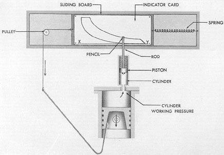
Figure 9-5 shows the fundamental principle of the operation of an engine indicator in
which the movement of the piston is recorded.
The indicator equipment includes a small cylinder that can be attached to the main working
cylinder of the engine, a piston and rod that
work in this small cylinder, with a pencil on the
end of the rod. The pencil point bears on the
paper tacked to the drum which is moved by
hook and string over a pulley. Any pressure in
the working cylinder enters the indicator cylinder and forces the small indicator piston and
pencil in a vertical direction at the same time
the main piston moves the card in a horizontal
direction by means of the string and pulley.
It is readily seen that any vertical distance
on the diagram will represent pressure, and the
horizontal distance will represent piston movement. As an example, in a two-stroke cycle engine, one complete revolution or cycle would
produce a diagram like the one shown in the illustration. This diagram is called an indicator
card. If the indicator spring is calibrated so that
the number of pounds of pressure required to
raise the pencil 1 inch is known, then to read
the pressure at any point on the card all that is
necessary is to measure the distance in inches
from the atmospheric line X-Y on the diagram
to the point at which the amount of pressure is
desired, and multiply this by the calibration
number of the spring. The total length of the
diagram represents the stroke of the piston. This
horizontal scale then can be laid off in inches,
feet, piston stroke, or volume of piston displacement.
This type of indicator is little used by
operating personnel on fleet type submarines
today, mainly because there is no provision
made on modern engines for the attachment of
the equipment necessary to take the indicator
card, and also because there are no means of
compression adjustment other than complete
overhaul of the engine.
The other type of indicator (indicating
maximum pressures only) is used to some extent for taking maximum cylinder pressures, to
check against manufacturer's test data and previous shipboard pressure tests. The two most
commonly used indicators of this type are the
Premax indicator and the Kiene indicator.
The method normally used to check the
equal distribution of power among the various
cylinders is to compare the exhaust gas temperatures of the cylinders by means of thermocouples placed in the exhaust elbows of each
cylinder. Pyrometer readings have proved to be
a good check on the general running conditions
of an engine, and the records of exhaust gas temperatures are of great value in conjunction with
indicator readings as aids in getting the best
results from a diesel engine. However, even
though the exhaust temperatures are normal,
the engine at times may not develop its rated
horsepower.
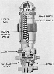
9E3. Premax indicator. The Premax indicator is an instrument for determining cylinder
187
Figure 9-5. Principle of engine indicator.
Figure 9-6. Premax pressure indicator.
Figure 9-7. Kiene pressure indicator.
188
compression and firing pressures. The indicator
consists essentially of a piston subject to cylinder pressure, a spring against which the piston
acts and the tension of which is adjustable by
means of an index sleeve, a control switch, and
a neon light circuit that shows if the piston is
moving. It is attached to the cylinder indicator
cock in the same way as any other indicator.
The pressure acting on one side of the piston in
the indicator is gradually increased by increasing the spring tension with the index sleeve until
this spring pressure is equal to the maximum
cylinder pressure which acts on the opposite
side of the piston. When the two pressures are
equal, the piston stops moving, as shown by
stopping of the neon light flashes. The pressure
reading is then read on the scale sleeve.
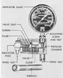
9E4. Kiene indicator. The Kiene diesel indicator is a pressure indicator gage for measuring the compression and firing pressure of an engine while it is running. The complete unit
consists of a pressure gage and an air-cooled
pressure chamber which is attached to the cylinder indicator cock.
The cylinder discharge passes through the
indicator plug up through the filler, screen, and
seat piece. This raises the valve, allowing the
gas to pass through the drilled holes in the guide
piece into the pressure chamber and on to the
gage. The action of the gas in the curved tube
of the gage tends to straighten the tube, thereby
moving the gage needle and recording the pressure on a calibrated scale.