2A1. Fundamental and standard units. In
order to understand and operate an engine efficiently it is necessary for the operator to be
familiar with various units of measurement and
the instruments by which they are recorded. As
soon as any branch of science is developed to
any extent, attempts are made to measure and
evaluate the quantities and conditions found to
exist. To do this a unit must be selected for
each measurable quantity. These units are derived from a set of basic units known as fundamental units. The fundamentalunits are units
of force, length, and time.
Fundamental units should not be confused
with standard units. Standard units of measurement are units that are established and legalized
by the government of a country. Whenever
standardized units are established, the fundamental units are expressed in terms of the
standard units to secure uniformity of procedure
and comparison.
2A2. The metric system of measurement.
The metric system of measurement is used generally throughout the world, particularly in
Europe. It is not in general use in the United
States. Because the metric system is a decimal
system, it is less subject to arithmetical error
than the other common system, the English
system of measurement. Since the metric system
uses the simple multiplier, 10, it is easy to
establish the value of the unit of measure as
denoted by the prefix in the name of the unit.
The table below explains how the prefix denotes
the value of the unit of measure and gives examples of the use of the prefix.
Prefix
Example
micro (meaning millionth)
micron, micrometer
milli (meaning thousandth)
millimeter, milligram
centi (meaning hundredth)
centimeter, centigram
deci (meaning tenth)
decimeter, decigram
deka (meaning ten)
dekameter
hecto (meaning hundred)
hectometer
kilo (meaning thousand)
kilometer
In the metric system the fundamental units
of force, length, and time are expressed in the
standard units of kilograms, meters, and seconds.
Such units as length, volume, and mass are
easily converted to the next higher denomination by using the simple multiplier, 10. For
example:
Units of Length
10 millimeters = 1 centimeter
10 centimeters = 1 decimeter
10 decimeters = 1 meter
1000 meters = 1 kilometer
Units of Weight
10 milligrams = 1 centigram
10 centigrams = 1 decigram
10 decigrams = 1 gram
1000 grams = 1 kilogram
1000 kilograms = 1 metric ton
The metric system has been legalized for
use in the United States and is frequently used
in scientific and laboratory work, because the
smaller units facilitate work of extreme accuracy
and the use of the simple multiplier, 10, makes
computation of work quick and easy.
2A3. The English system of measurement.
The English system of measurement is by far
the most commonly used in engineering work
in the United States. The system is given wide
usage primarily because of precedent rather
than because of any recommending features
such as those encountered in the metric system.
In the English system the fundamental
units of force, length, and time are expressed in
the standard units of foot, pound, and second.
Unlike the metric system, the English system
has no common multiplier and the subdivisions
of the units of measurement bear no common
relation to each other. For example, below are
given the units of length and weight and the
relationship of the various subdivisions of each.
Units of Length
12 inches = 1 foot
3 feet 1 yard
5 1/2 yards = 1 rod (16 1/2 feet)
Units of Weight
16 ounces = 1 pound
2000 pounds = 1 ton (short)
2240 pounds = 1 ton (long)
21
Since all forms of matter are measurable
in terms of the fundamental units of force,
length, and time, it is possible to combine the
units of measurement to express measurement
of quantities encountered in various engineering
and scientific work. In the following sections,
the English and metric units of measurement in
engineering work are discussed. In the description of each, it is easy to see how each of these
units of measurement may be basically reduced
to fundamental units.
2A4. Unit of length. Length is usually defined as the distance between two points. In the
English system it is expressed in inches, feet,
yards, rods, miles, or fractions thereof. The accuracy required in engineering work makes it a
general practice for engineers to measure length
in thousandths of an inch. Thus, various tolerances, clearances, and minute measurements are
expressed by decimal divisions of an inch in
thousandths, such as .125 (one hundred twenty
five thousandths).
In a problem involving measurement of
area, the area of a regular shape may be expressed by the product of two measurements of
length. Thus, a square 3 feet by 3 feet has 9
square feet of area. Likewise, a problem of
measuring volume, where the shape is adaptable
to linear measurement, may be expressed by the
product of three measurements of length. Thus,
a cube 3 feet by 3 feet by 3 feet has 27 cubic
feet of volume.
2A5. Conversion factors of length. Often
when using the English system in engineering
work it is necessary to convert measurements to
the metric system and vice versa. To change
units of one system to those of another it is
necessary to have a conversion factor that establishes the relation between the two systems for
the same quantity. The most commonly used
conversion factors between the English and
metric systems are:
English System
Metric System
1 inch
=
2.54 centimeters
39.37 inches
=
1 meter
All English system measurements of length
may be reduced to inches and all metric system
measurements of length to centimeters. Knowing the basic conversion factor, inches can be
converted to centimeters by multiplying inches
by 2.54, and centimeters converted to inches by
dividing centimeters by 2.54,
2A6. Unit of force. Force is the push, pull,
or action upon a body or matter at rest which
tends to give it motion. In the English system,
the unit of force is the pound. In the metric system, the unit of force is the kilogram.
2A7. Unit of work. The work done upon a
body is equal to the average force acting upon
the body multiplied by the distance through
which the body is moved as a result of the force.
In the English system, the unit of work is
the foot-pound. For example, if a force of 500
pounds acts upon a body to move it 10 feet,
5000 foot-pounds of work have been done upon
this body.
2A8. Units of mass and weight. The mass of
a body may be defined as the quantity of matter
in a body without regard to its volume or the
pull of gravity upon it. The term mass must be
distinguished from the term weight which is the
measurement of the force of gravity acting upon
body at any given point upon the earth's surface. Weight varies with locality, but mass is
considered constant. The student must not confuse mass with weight although the units are the
same for both. The standard kilogram is defined
as the mass of a certain piece of platinum
iridium in possession of the International Bureau of Weights and Measures. The fundamental
unit of mass, the gram, is one one-thousandth of
the standard kilogram.
English System
Metric System
1 ounce
=
26.35 grams
1 pound
=
0.454 kilograms
1 gram
=
0.0353 ounces
1 kilogram
=
2.205 pounds
Kilograms are converted into pounds by
multiplying the number of kilograms by 2.205,
and conversely pounds are converted into kilograms by multiplying the number of pounds by
0.454. For example, 1 metric ton (1000 kilograms) equals 1000 x 2.205 or 2205 pounds.
2A9. Unit of pressure. Pressure is defined
as force per unit area acting against a body. In
the English system, the unit of pressure may be
expressed as pounds per square inch or pounds
per square foot.
Since all forms of matter have weight, the
air of the earth's atmosphere has weight. At sea
22
level, the weight of air exerts a pressure of 14.7
pounds per square inch and has a weight of
approximately 0.08 pounds per cubic foot. At
higher altitudes, the pressure, and therefore the
weight, becomes less.
Gage pressure. Pressure gages are commonly used to determine the pressure existing
or to record the peak pressure attained within a
container. Most pressure gages make no allowance for atmospheric pressure and normally
register zero at existing atmospheric pressure.
Absolute pressure. In practically all pressure problems, atmospheric pressure is present
and must be accounted for. When atmospheric
pressure is added to the gage or indicated pressure, the total obtained is the absolute pressure.
Thus, absolute pressure is the total pressure
recorded from a zero point. For example, the
scavenging air pressure in a cylinder is 4 psi. If
the cylinder is at sea level, the atmospheric pressure of 14.7 psi must be added, making the
total 18.7 psi absolute pressure.
2A10. Unit of power. Work has been defined as force acting through a given distance.
Power may be defined as the amount of work
performed during a unit period of time. The
unit of power used by engineers is the horsepower. One horsepower (hp) equals the amount
of work necessary to raise 33,000 pounds
through a distance of 1 foot in 1 minute. One
horsepower also equals the amount of work
necessary to raise 550 pounds through a distance of 1 foot in 1 second.
Example: How many horsepower are required to raise a weight of
12,000 pounds through a distance of 22 feet in 2 minutes?
Solution: (12,000 x 22)/(2 x 33,000) = 4 horsepower
2A11. Unit of temperature. Temperature
may be defined as the measure of intensity of
heat. In simple language, temperature is the
measure of hotness (usually referred to as high
temperature) or coldness (usually referred to as
low temperature) of a body or matter.
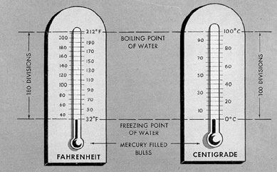
Temperature is measured and expressed in
degrees according to established standard scales
known as the Fahrenheit and centigrade scales.
The Fahrenheit scale is established with a range
of 180 degrees or graduations between the freezing point and the boiling point of pure water at
sea level. On the Fahrenheit scale the freezing
point of water is fixed at 32 degrees and the boiling
point of water at 212 degrees. The centigrade scale is
established with a range of 100 degrees or graduations between the freezing point and the boiling point of water at sea level. On the centigrade scale the freezing point of water is fixed
at 0 degrees and the boiling point of water at 100 degrees.
a. Absolute zero temperature. Absolute
zero temperature is theoretically the lowest temperature that can be obtained. It is that temperature at which all molecular motion ceases entirely and at which point the given matter
possesses no heat whatsoever. Absolute zero
temperature has been determined to be -273 degrees
C and -459.6 degrees F. From a practical standpoint,
absolute zero is unattainable.
b. Conversion factors of temperature.
Since the centigrade scale covers the same temperature range (freezing to boiling points of
water) in 100 degrees that the Fahrenheit scale
covers in 180 degrees, a centigrade degree
equals 9/5 of a Fahrenheit degree. Hence, a
centigrade reading may be converted to a Fahrenheit reading by multiplying the centigrade
reading by 9/5 and adding 32 degrees. And,
conversely, a Fahrenheit reading may be converted to a centigrade reading by subtracting 32
degrees and multiplying by 5/9.
Expressed as a simple equation, the conversion factor is:
F = 9/5 C + 32
C = 5/9 (F - 32)
Example: How many degrees centigrade
are 86 degrees Fahrenheit?
Solution: C = 5/9 x (86 - 32) = 30
degrees C.
Example: How many degrees Fahrenheit
are 35 degrees centigrade?
Solution: F = 9/5 x 35 + 32 = 95
degrees F.
2A12. Unit of heat. Heat is a form of energy,
and the English system unit of heat is the mean
British thermal unit (Btu). The British thermal
unit is the amount of heat necessary to raise the
temperature of 1 pound of water 1 degree F at
sea level atmospheric pressure.
23
When 1 pound of fuel oil is completely
burned, a certain number of Btu of heat are
given off. The quantity of heat liberated by the
complete combustion of 1 pound of fuel oil is
known as the fuel oils heating value.
Since heat is a form of energy, it cannot be
destroyed but may be converted into mechanical energy. One Btu of heat is equivalent to 778
foot-pounds of work. Thus, the conversion factor
for power to heat is:
1 hp = 33,000 / 778 = 42.42 Btu per minute
2A13. Unit of time. The standard unit of
time in both the English system and the metric
system is the second. The second is defined as
1/86,400 part of a mean solar day. The mean
solar day is obtained by taking the average
length of all the days of the year, a day being
measured from the noon of one day to the noon
of the next.
The multiples of the units of time are:
60 seconds = 1 minute
60 minutes = 1 hour
24 hours = 1 day
2A14. Units of velocity. Velocity may be
defined as the rate of movement of a body. If a
body moves a specified distance during a specified time at a uniform speed, the velocity may
be determined by dividing the distance by the
time. There are two types of velocity normally
encountered, linear and angular. If the velocity
is linear, the movement is in a straight line and
the velocity may be expressed in terms such as
feet per second, feet per minute, or miles per
hour. If the velocity is angular, the movement of
the body is rotary or about a central axis, and
the velocity may be expressed in revolutions
per minute or revolutions per second. In engineering work it is common practice to rate the
velocity of shafts, wheels, gears, and other rotating parts in revolutions per minute (rpm).
B. INSTRUMENTS
2B1. General. In the previous section we
have defined and explained the fundamental
units of measurement and the standard units of
measurement for both the English and the
metric systems. It is the purpose of this section
to enumerate and describe the various instruments by which these measurements are computed and recorded.
2B2. Instruments for measuring length. a.
General. In engineering and machine work
there are several instruments for measuring
length, area, and volume. Since the measurement
of area and volume often can be obtained by
compounding simple measurements of length,
instruments used for computing area and volume are also described here.
b. Rulers and tapes. The most common
method of obtaining simple measurements of
length is by the ruler or tape (Figure 2-1). A
ruler may be graduated into feet, inches, or
fractions thereof. Rulers and tapes used in engineering work are most frequently made of metal
and the fractions of inches may be graduated to
subdivisions as small as 1/64 or 1/100 of an
inch. Care should be exercised in using metal
rulers and tapes, especially if extreme accuracy
is required. The margin of error due to
expansion or contraction of the instrument from
changes in temperature can be considerable.
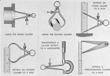
c. Calipers. Engineers and machinists
frequently use calipers to secure accurate measurements of inside and outside diameters. Figure
2-2 shows how various caliper settings may be
taken and how the registered setting of the
calipers may be measured by a ruler or by a
micrometer.
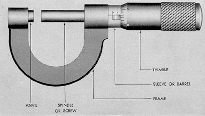
d. Micrometer calipers. Engineers frequently rely on the micrometer caliper (Figure
2-3) to obtain measurements accurate to
1/1000 of an inch. This instrument is particularly useful for measuring relatively short
lengths and the diameter of journals or cylinders. The common commercial micrometer consists of a frame; an anvil, or fixed measuring
point; a spindle; a sleeve, or barrel; and a
thimble. The spindle has threads cut 40 to the
inch on the portion that fits inside the sleeve.
The thimble fits over the end of the sleeve, and
rotating the thimble turns the spindle.
Rotating the thimble until the spindle has
made one complete turn moves the spindle 1/40
of an inch, which is equal to 0.025 inch. The
number of turns the spindle makes is indicated
by graduations on the sleeve. Each graduation
24
Figure 2-1. Common ruler, machinist's ruler, and steel tape.
represents one complete turn and every fourth
graduation is marked 1, 2, 3, and so on, to represent 1/10 of an inch. Thus, each number is
equivalent to the sum of four graduations, or
4 x 0.025, which equals 0.100 inch.
The thimble has a beveled edge divided
into 25 parts and numbered 0, 5, 10, 15, 20, and
back to again. Each of these marks represents
1/25 of a turn or 1/25 of 0.025 which is
1/1000 (0.001) of an inch. A final reading of
the micrometer is obtained by multiplying the
number of graduations on the sleeve by 25 and
adding the number of marks indicated on the
beveled edge of the thimble. This gives the
reading in thousandths.
For example, in Figure 2-3 the graduations
on the sleeve show the spindle has turned 7
revolutions which is equivalent to 7 x 0.025, or
0.175 inch. The thimble has been turned 3
marks, or 0.003 inch. The total reading then is
0.175 plus 0.003, or 0.178 inch.
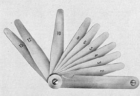
e. Feeler gages. The feeler gage (Figure
2-4) comes into frequent use in engineering and
machine work. Such a gage consists of thin
blades of metal of various thicknesses. There is
generally a blade or strip for each of the most
commonly used thicknesses such as 0.002 inch,
0.010 inch, and .015 inch. The thickness of each
blade is generally etched on the blade.
Feeler gages are principally used in determining clearances between various parts of
machinery. Probably the most common use is
determining valve clearance. Various blades are
inserted between the tappet and the push rod
until a blade of the feeler gage is found that will
just slide between the two surfaces without too
much friction or sticking. The thickness of the
blade then determines the clearance. Or, a particular feeler of proper thickness may be selected
and the tappet adjusted until the feeler will
just slide between the tappet and push rod with
out catching.
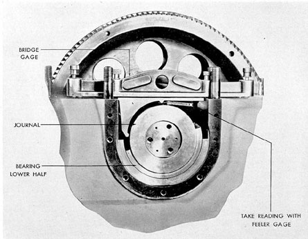
f. Bridge gages. Bridge gages are used
to measure the amount an engine main bearing has dropped due to wear. Figure 2-5 shows
25
Figure 2-2. Types of calipers and methods of measurement.
Figure 2-3. Micrometer.
26
a bridge gage in use. The upper
cap of the main bearing has been
removed and the bridge gage has
been placed over the journal as
shown. A feeler gage is then inserted between the tip of the bridge
gage and the journal. The measurement recorded by the feeler gage
is then compared to the original
measurement taken at the time the
engine was installed or with previous bridge gage readings. Thus, the
amount of bearing wear can be
determined.
Bridge gages must be handled
with great care. If the tip on the
gage or the supporting surfaces
becomes burred, worn, or distorted,
the gage will give an inaccurate
reading.
Figure 2-4. Feeler gage.
Figure 2-5. Using bridge gage and feeler gage to determine clearance.
27
2B3. Instruments for measuring temperature.
a. General. As previously stated, temperature is a measure of the intensity of heat, and
the measurements may be made with one of
several instruments. The instruments most commonly used for measuring temperatures below
1000 degrees F are the mercury thermometer, the
thermocouple pyrometer, and the electrical resistance thermometer. For taking temperature
measurements above 1000 degrees F, the most commonly used instrument is the thermocouple
pyrometer.
In taking measurements with thermometers
and pyrometers, the operator should bear in
mind the possibility of errors in measurement
and what effect they may have on his particular
problem. An error is the difference between the
observed value and the true value and may be
expressed as a percentage. Some errors inherent
in an instrument may be avoided by periodically
checking the calibration of an instrument with
one of known accuracy. Sometimes, errors due
to the aging or failure of materials in the instrument are unavoidable, such as the deterioration
of glass due to aging and repeated stress. A
check of the instrument will indicate the
percentage of error present.
b. Liquid-in-glass thermometers. In the
type of thermometer in which a hollow glass
stem is filled with a liquid (Figure 2-6) the
liquid most commonly used is mercury, although
some thermometers are filled with alcohol or
pentane. In some cases, where extremely low
temperatures are to be recorded, a gas may
be used. In the construction of the common
mercury thermometer, care is used in sealing
the stem to insure that a vacuum exists above
the column of mercury in the stem. Otherwise, the mercury would have to compress the
air in the stem, and a false reading would result.
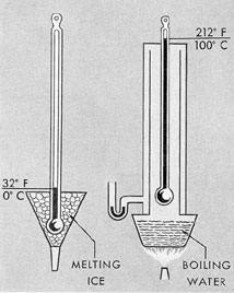
To graduate a thermometer (Figure 2-7)
the bulb and a portion of the stem holding the
mercury are submerged in melting ice and the
point at which the mercury stands in the tube
is marked 32 degrees if the thermometer is Fahrenheit, or 0 degrees if the thermometer is centigrade.
Next, the bulb and stem are placed in a closure
in which they are surrounded by steam rising
off boiling water at sea level atmospheric pressure. The position of the top of the column of
mercury is then marked at 212 degrees if the thermometer is Fahrenheit, or at 100 degrees if the
Figure 2-6. Fahrenheit and centigrade thermometers.
28
thermometer is centigrade.
On Fahrenheit thermometers the distance
between the 32 degrees and the 212 degrees marks is graduated and marked into 180 equal parts, each
space or subdivision representing 1 degrees F. On centigrade thermometers the distance between the 0 degrees
and 100 degrees marks is graduated and marked into
100 equal parts, each space representing 1 degree C.
The space above and below these markings is
calibrated into the same graduations for the entire temperature range of the thermometer.
Figure 2-7. Method of graduating thermometers.
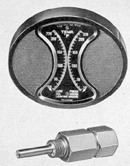
c. Electrical resistance thermometers.
Electrical resistance thermometers (Figure 2-8)
make use of the principle that the electrical
resistance of various metals varies with their
temperature. The resistance is measured by a
Wheatstone bridge which is connected to a galvanometer calibrated to read in degrees of temperature. One leg of the balanced bridge circuit
is led to the thermometer bulb which is inserted
at the point where the temperature is to be
measured. A temperature change at the thermometer bulb will change the resistance with
regard to the circuit, causing an electrical unbalance in the entire bridge. This unbalance will
cause the galvanometer pointer to move across
its scale accordingly. Metals commonly used in
the thermometer bulb are platinum and nickel.
Figure 2-8. Electrical resistance thermometer dial
and bulb.
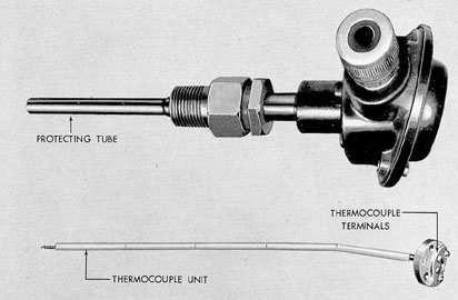
d. Thermocouple pyrometers. The thermocouple unit of the pyrometer (Figure 2-9).
is made of two wires or strips of dissimilar metals connected at one end and having an electrical
connection at the other end. When the two ends
or junctions are subjected to different temperatures, an electrical current is generated. This
current is measured to give an indication of the
differences in temperatures between the two
junctions. In submarines the most common application of this instrument is for measuring the
exhaust temperature in the exhaust elbows of
the engine. One of the two thermocouple wires
is made of pure iron and the other is made of
constantan, a nickel copper alloy. The wires are
twisted together and welded at the tip of the
thermocouple and mounted in the closed end of
the protecting tube made of pure nickel. The
protecting tube is fitted with a terminal head in
which the connections are made between the extension leads and the thermocouple wires. These
connections between the thermocouple and the
29
Figure 2-9. Thermocouple pyrometer and thermocouple unit.
indicating instrument are made with wires of
the same material as the thermocouple and
cause the cold junction to be extended from the
thermocouple terminals back to the indicator.
Other types of wires are never used for this
purpose.
2B4. Instruments for measuring pressure.
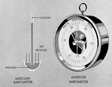
a. Barometers. The most common instrument
in use for measuring atmospheric pressure is the
mercury barometer (Figure 2-10). This instrument consists of a long, hollow, glass tube,
sealed at one end and with the open end of the
tube submerged beneath the surface of an open
container of mercury. An increased air pressure
acting upon the surface of the mercury in the
open container causes the mercury to rise in
the tube. The space between the mercury and
the sealed end inside the tube is a vacuum so
that air will not be compressed in the tube and
counteract the pressure exerted outside. The
tube containing the column of mercury is calibrated in inches and subdivisions of 1/100 of
an inch. As atmospheric pressure acting upon the
surface of the mercury in the open container
varies, the column of mercury in the tube rises
and falls and the amount can be measured by
the calibrations on the tube. When the column
of mercury stands at 29.92 inches at 32 degrees F and
at sea level, standard atmospheric pressure is
registered.
Another type of barometer is the aneroid
barometer (Figure 2-10). The aneroid barometer consists of an exhausted chamber with
corrugated diaphragm walls. Atmospheric pressure causes the diaphragm walls to deflect
against the resistance of a spring. The deflections
of the diaphragm walls against the spring are
recorded by a lever or indicator upon a calibrated face through a delicate system of levers.
Some aneroid barometers are so sensitive that
they will register a change when raised or lowered only a few feet. Due to the effect of aging
and fatigue of the diaphragm construction, aneroid barometers should have their calibrations
30
frequently checked against mercury barometer
readings.
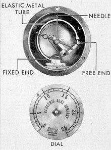
b. Pressure gages. Pressure gages (Figure 2-11) of the diaphragm or tube type are
generally used for determining the pressure of
steam, water, air, and other mediums. The aneroid barometer described above is an example
of the diaphragm type pressure gage. However,
the tube type gage is considered more accurate.
Such a gage is called a Bourdon gage. The simplex pressure gage illustrated in Figure 2-11 is
a Bourdon type gage. This gage consists of an
elastic metal tube of oval cross section, bent
into an arc. The two metals commonly used in
making the tube are brass and steel. In low-pressure gages, brass is normally used but if the
pressures to be measured exceed 100 psi, the
tubes are always constructed of steel. One end
of the tube is fixed and the other end is movable. The free end of the tube is connected to a
spring-loaded needle through a gear and system
of levers. Pressure exerted on the inside walls of
the oval tube tends to make the tube straighten
out. The free end of the tube pulls on the end
of the lever, the motion of which is transmitted
to the needle. The needle registers across the
face of the dial, and the gage is calibrated so
that it will indicate the pressure in pounds per
square inch.
2B5. Instruments for measuring volume.
a. Sounding. One of the most common measuring problems in diesel engineering is determining the volume of fluid remaining in fuel oil and
lubricating oil tanks. The simplest and most
accurate method of determining the volume of
fluid in a tank is by sounding. In submarine
fuel systems, as fuel is withdrawn from a tank,
it is replaced by compensating water. Small
sounding tubes of various lengths are installed
in the tanks to determine whether there is oil
or water at various levels.
b. Fuel oil meters. Fuel oil meters are also
used in submarine fuel systems to indicate the
amount of fuel withdrawn from the main fuel
tanks. Fuel oil meters should be checked frequently for accuracy. Strainers should be
Figure 2-10. Mercury and aneroid barometers.
31
Figure 2-11. Simplex tube type pressure gage and dial.
installed in the line to the fuel oil meter to prevent any foreign substance from getting into
the meter mechanism and affecting the accuracy of its registration.
c. Liquidometers. In submarines, liquidometers are frequently used to determine: 1) the
level of the liquid in a partially filled tank, and
2) the level between two dissimilar liquids in
a completely filled tank.
The liquidometer is equipped with a float
mechanism, the movement of which actuates a
double-acting opposed hydraulic mechanism
which registers upon a calibrated dial the volume of the desired liquid.
2B6. Instruments for measuring rotational
speed. a. General. Aboard ship it is often
imperative to know the rotational speed of an
engine or piece of machinery which is generally
measured in rpm. Various instruments such as
revolution counters, mechanical tachometers,
and electrical tachometers, are available for securing this measurement.
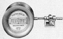
b. Revolution counters. Revolution counters (Figure 2-12) used aboard ship are principally of three types: mechanical, electrical, and
electro-mechanical. The mechanical type may
be either of the rotating type or the oscillating
ratchet type. Probably the most accurate of
the common counter devices is the rotating
counter with a magnetic clutch connector and
a synchronous electric timer operated by the
same switch. It is frequently used for calibrating other counters.
The rotating continuous counter may have
direct-reading wheels of the cyclometer type
or may operate dials or pointers through a gear
train. The oscillating or stroke counter is
adapted for low speeds only. Rotating counters may be obtained for high-speed work, up
to 5000 rpm. It is important that a counter
not be used for speeds higher than the speed
limits recommended by the manufacturer.
Figure 2-12. Mechanical revolution counter.
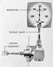
c. Mechanical tachometers. Tachometers
(Figure 2-13) are measuring instruments that
give a direct and continuous indication of rotary speed in rpm. For submarine diesel engines, the mechanical tachometers are usually
permanently mounted on a gage board. They
are generally driven from the engine camshaft
through a gearing and a flexible shaft. In operation, the force produced by the rotation is
balanced against a calibrated spring or against
the force of gravity. Those used in submarines
are usually of the indicator type in which the
pointer registers the rpm at the moment, rising
and falling with the fluctuations in engine
speed.
32
Hand type tachometers have frequent use
in engineering work. This type of tachometer
is generally held in the hand and pressed firmly
against the end of a rotating shaft to register the
rpm directly. Some types of hand tachometers
have several sets of change gears so that a
wide range of rotary speeds may be accurately
read with a single instrument.
Figure 2-13. Mechanical tachometer.
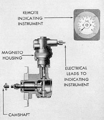
d. Electrical tachometers. Electrical
tachometers (Figure 2-14) of the indicating
type are used with submarine diesel engines.
The drive mechanism for the electrical tachometer is actuated by the engine camshaft. The
drive in turn powers a tachometer magneto and
Figure 2-14. Electrical tachometer.
the electric current generated actuates an indicator which is calibrated to register engine revolutions per minute. The electrical tachometer
possesses the distinct advantage that the indicating instrument may be mounted at a distance
from the drive mechanism.
All tachometers should be checked frequently for accuracy. This check can be made
by using a mechanical revolution counter which
is 100 percent accurate. The tachometer is
checked against the counter for several minutes
with a stop watch and then the reading on the
counter is divided by the number of minutes
to check the number of rpm.