4A1. General. In a submarine, the principal ballast is water. Therefore, the arrangement
of tanks built into the ship establishes the points at which water ballast may be concentrated. It is
the arrangement of these tanks that makes possible controlled diving and surfacing and the
maintenance of diving trim at any depth. The arrangement of the tanks, with respect to the center
of buoyancy, establishes the lever arm for maintaining fore and aft balance and athwartship
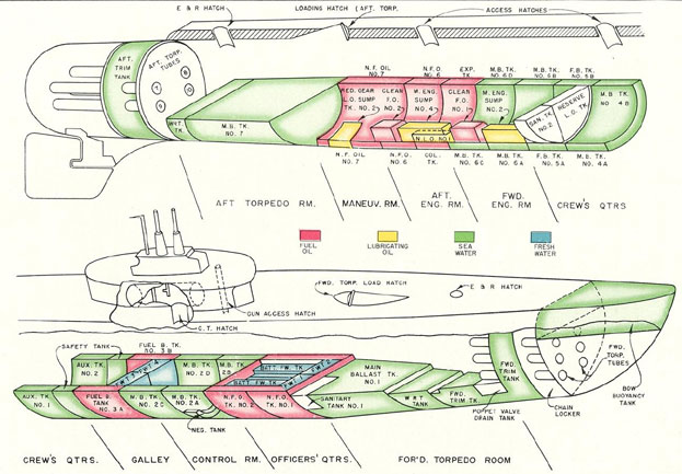
stability. FigureA-3 shows, in schematic form, the general arrangement of the tanks within a
submarine.
The water ballast tanks are divided into four main groups: the main ballast tanks, the variable
ballast tanks, the special ballast tanks, and the fuel oil ballast tanks.
4A2. Main ballast tanks. The main ballast tanks group consists of four groups, which
are further subdivided into ten tanks, as follows:
TANK
CAPACITY
1. MBT No. 1
49.17 tons sea water
2. MBT Nos. 2A, 2B, 2C and 2D
129.03 tons sea water (4 tanks)
3. MBT Nos. 6A, 6B, 6C and 6D
141.60 tons sea water (4 tanks)
4. MBT No 7
39.09 tons sea water
4A3. Variable ballast tanks. The second group of water tanks is the variable ballast
tank group which is composed of six tanks as follows:
TANK
CAPACITY
1. Forward trim tank
24.31 tons sea water
2. Forward WRT tank
4.94 tons sea water
3. Auxiliary ballast tank No. 1
30.77 tons sea water
4. Auxiliary ballast tank No. 2
30.77 tons sea water
5. After trim tank
19.97 tons sea water
6. After WRT tank
5.06 tons sea water
4A4. Special ballast tanks. The safety, negative, and bow buoyancy tanks are classified
as special ballast tanks. Each of these
tanks has special blowing arrangements and a special purpose, which is described in detail in later
sections of this chapter.
TANK
CAPACITY
1. Safety tank
23.23 tons sea water
2. Negative tank
7.51 tons sea water
3. Bow buoyancy tank
31.69 tons sea water
39
4A5. Fuel Ballast tanks. There are three fuel ballast tanks divided into A and B sections
which are connected together through
limber holes in the vertical keel plating. The tanks are as follows:
TANK
CAPACITY
1. Fuel ballast tanks Nos. 3A and 3B
19,196 gallons
2. Fuel ballast tanks Nos. 4A and 4B
24,089 gallons
3. Fuel ballast tanks Nos. 5A and 5B
19,458 gallons
The fuel ballast tanks normally carry fuel oil. When not being used as fuel ballast tanks, they
may be used as main ballast tanks.
4A6. Additional tanks. In addition to the above-named water ballast tanks, there are the
normal fuel oil tanks, collecting tank,
expansion tank, clean fuel oil tank, normal lubricating oil tank, reserve lubricating oil tank, main
sump tanks, reduction gear sump tanks, fresh water tanks, emergency fresh water tanks, battery
fresh water tanks and sanitary tanks. The capacity of these tanks is given in the following table.
TANK
CAPACITY
Normal fuel oil tank group:
1. NFOT No. 1
11,401 gallons
2. NFOT No. 2
13,122 gallons
3. NFOT No. 6
15,201 gallons
4. NFOT No. 7
10,054 gallons
5. Collecting tank
2,993 gallons
6. Expansion tank
2,993 gallons
Clean fuel oil tank group:
1. CFOT No. 1
611 gallons
2. CFOT No. 2
618 gallons
Normal lubricating oil tank group:
1. NLOT No. 1
1,475 gallons
2. NLOT No. 2
924 gallons
3. NLOT No. 3
1,073 gallons
4. Reserve lube oil tank
1,201 gallons
40
TANK
CAPACITY
Main engine sump tank group:
1. Main engine sump No. 1
382 gallons
2. Main engine sump No. 2
382 gallons
3. Main engine sump No. 3
382 gallons
4. Main engine sump No. 4
382 gallons
5. Reduction gear sump No. 1
165 gallons
6. Reduction gear sump No. 2
165 gallons
Fresh water tank group:
1. Fresh water tank No. 1
980 gallons
2. Fresh water tank No. 2
980 gallons
3. Fresh water tank No. 3
973 gallons
4. Fresh water tank No. 4
973 gallons
5. Emergency fresh water tanks
276 gallons (total)
a. 2 tanks forward torpedo room
276 gallons (total)
b. 1 tank control room
18 gallons
c. 1 tank maneuvering room
8 gallons
d. 1 tank aft torpedo room
180 gallons
Battery water tanks:
1,208 gallons (total)
1. Battery water tanks Nos. 1 and 2
152 gallons (each)
2. Battery water tank No. 3
143 gallons
3. Battery water tank No. 4
157 gallons
4. Battery water tank Nos. 5 and 6
152 gallons (each)
5. Battery water tank No. 7
157 gallons
6. Battery water tank No. 8
143 gallons
Sanitary tanks:
1. Sanitary tank No. 1
1.66 tons or 434 gallons
2. Sanitary tank No. 2
2.57 tons or 673 gallons
41
4A7. Test pressure and data. The tank and groupings, together with their capacities
outlined in Sections 4A2 and 4A6 inclusive, are those tanks which are designed to contain
liquids under any normal or emergency condition of operation of the vessel. These tanks are
subjected to the individual tests listed in the following chart:
TANK
TYPE OF TEST
1. MBT No. 1
A. S. & T. 15 psi Tests made
2. MBT Nos. 2A and 2B, 2C and 2D
A. S. & T. 15 psi before flood
3. MBT Nos. 6A and 6B, 6C and 6D
A. S. & T. 15 psi ports are cut
4. MBT No. 7
A. S. & T. 15 psi into tank.
5. Forward trim tank
W. S. & T. Test depth
6. Forward WTB tank
W. S. & T. Test depth
7. Auxiliary tank No. 1
W. S. & T. Test depth
8. Auxiliary tank No. 2
W. S. & T. Test depth
9. After trim tank
W. S. & T. Test depth
10. Safety tank
W. S. & T. Test depth
11. Negative tank
W. S. & T. Test depth
12. Bow buoyancy
W. S. & T.
13. FBT Nos. 3A and 3B
W. S. & T. 102 ft. head to keel
14. FBT Nos. 4A and 4B
W. S. & T. 102 ft. head to keel
15. FBT Nos. 5A and 5B
W. S. & T. 102 ft. head to keel
16. NFOT No. 1
W. S. & T. 102 ft. head to keel
17. NFOT No. 2
W. S. & T. 102 ft. head to keel
18. NFOT No. 6
W. S. & T. 102 ft. head to keel
19. NFOT No. 7
W. S. & T. 102 ft. head to keel
20. Collecting tank
W. S. & T. 102 ft. head to keel
21. Expansion tank
W. S. & T. 102 ft. head to keel
22. CFOT No. 1
W. S. & T. 60 ft. head to keel
23. CFOT No. 2
W. S. & T. 60 ft. head to keel
24. NLOT No. 1
W. S. & T. 35 ft. head to keel
25. NLOT No. 2
W. S. & T. 35 ft. head to keel
26. NLOT No. 3
W. S. & T. 35 ft. test depth
27. Reserve lube oil tank
W. S. & T. 35 ft. head to keel
28. Main engine sump No. 1
W. S. & T. 35 ft. head to keel
29. Main engine sump No. 2
W. S. & T. 35 ft. head to keel
42
TANK
TYPE OF TEST
30. Main engine sump No. 3
W. S. & T. 35 ft. head to keel
31. Main engine sump No. 4
W. S. & T. 35 ft. head to keel
32. Reduction gear sump No. 1
W. S. & T. test depth
33. Reduction gear sump No. 2
W. S. & T. test depth
34. Fresh water tank No. 1
A. S. & T. 18 psi
35. Fresh water tank No. 2
A. S. & T. 18 psi
36. Fresh water tank No. 3
A. S. & T. 18 psi
37. Fresh water tank No. 4
A. S. & T. 18 psi
38. Emergency fresh water tank No.
A. S. & T. 10 psi
39. Battery water tanks Nos. 1 and 2
A. S. & T. 18 psi
40. Battery water tank No. 3
A. S. & T. 18 psi
41. Battery water tank No. 4
A. S. & T. 18 psi
42. Battery water tanks Nos. 5 and 6
A. S. & T. 18 psi
43. Battery water tank No. 7
A. S. & T. 18 psi
44. Battery water tank No. 8
A. S. & T. 18 psi
45. Sanitary tank No. 1
W. S. & T. test depth
46. Sanitary tank No. 2
W. S. & T. test depth
B. WATER BALLAST TANKS
4B1. Purpose of water ballast tanks. The water ballast tanks include the main ballast
tanks, the variable ballast tanks, and the special ballast tanks. The purpose of these tanks can best
be defined by illustration. Assume that a new 1,500-ton submarine is making its initial dive, and
that this trim dive is to be a stationary dive.
The ship has a surface displacement of 1,500 tons and draws 14 feet of water. When fuel oil
and lube oil tanks are completely filled, she draws 15 feet 6 inches of water and is ready for her
trim dive. The ship is on the surface and weighs 1,750 tons; this is the designed weight plus oil,
stores, and crew. The submarine is ready for sea. The problem is to take on weight enough so
that the ship will submerge to a depth at which the waterline will be even with the periscope
shears. (With a draft of 15 feet 6 inches,
the waterline is 31 feet 6 inches from the periscope shears.)
The weight taken on is water, and it is flooded into tanks. The air, of course, is vented off the
tanks as the water flows in. First, the large tanks, known as main ballast tanks, are
flooded. These tanks hold 359 tons of sea water. (See Section 4A2.) The submarine now
displaces 2,109 tons and draws approximately 22 feet of water. The main deck is not awash,
since there are approximately 2 feet from waterline to deck. The ship still has plenty of positive
buoyancy. Since the bow buoyancy tank vent has been open during this operation, allowing this
free-flooding tank to take on ballast as the ship submerges, it is necessary to add to the
displacement the weight of water taken on by the bow buoyancy tank (which belongs to the
special ballast tank group).
43
This gives a new total displacement of 2,141 tons (2,109 tons plus 32 tons).
Simultaneously with the flooding of bow buoyancy, the safety tank also in the special ballast
tank group, is flooded. This tank holds 23 tons of water, giving a total displacement of 2,173
tons and a draft of 24 feet. The decks are just awash, and some positive buoyancy is still retained,
although the submarine is approaching a condition of neutral buoyancy. Two things remain yet to
be done: 1) to take on additional weight, and 2) to distribute this weight so that fore-and-aft
athwartship balance is maintained. This additional weight is added to the variable ballast
tanks and distributed throughout the variable tanks by the trim system. With the ship in this
condition, approximately 55 tons of water must be added to the variable tanks to submerge to a
depth where the periscope shears are even with the waterline. The ship is not in a state of neutral
buoyancy and is balanced both fore-and-aft and athwartship. At this point, any additional ballast
taken on will cause the submarine to submerge; any ballast removed will cause it to rise (Figure 4-1).
However, neutral buoyancy is only a theoretical condition and is very difficult to maintain in
practice unless the force of
buoyancy is assisted by some outside force. On the submarine, this assistance is provided by the bow
and stern planes and by the propellers. If the trim adjustment is reasonably accurate, the ship will
be easily controlled by its planes and speed. To cruise at this depth, the main motors are started.
To go to periscope depth, the submarine can plane down with the bow and stern planes.
However, to go down in a hurry, it must change from a condition of neutral buoyancy to a condition of negative buoyancy. This is
done by flooding the negative tank. The submarine will then be diving 7 tons negative, and must
blow negative, therefore, to level off at any given depth, leaving only a water seal in the tank as it
approaches the desired depth, thus restoring neutral trim.
If it is desired to surface after returning to periscope depth, the safety tank is blown to restore
positive buoyancy, and the bow buoyancy tank is blown to give the ship a rise angle. Should a
greater freeboard be desired at the time of surfacing, the main ballast tanks must also be blown.
Note that the variable tanks are not blown. These tanks control the trim of the submarine.
Therefore, as long as the tanks contain the adjusted weights of water, the ship is in a condition of
diving trim.
C. MAIN BALLAST TANKS
4C1. Function and location. The main ballast tanks are water ballast tanks. They are
designated as main ballast tanks because they account for the greater percentage of the water
ballast normally carried. They have as their primary function the destroying or restoring of
positive buoyancy.
The main ballast tanks (MBT), FigureA-4, are located outside the pressure hull. All A and C
tanks are on the starboard side; all B and D tanks are on the port side. Tanks No. 1 and No. 7
extend from port to starboard. All other main ballast tanks are located between the pressure and
outer hull and are separated by light athwartship bulkheads.
4C2. Description. The main ballast tanks are provided with two to eight flooding
openings, located at the lowest point possible on the outer hull. These openings, located in MBT
No. 1, MBT Nos. 2A, 2B, 2D, 6A, 6B, 6C, 6D and MBT No. 7, are free flooding and are not
provided with flood valves. Main ballast tanks No. 2 and No. 6 have, in addition to their primary
function of destroying or restoring positive buoyancy, a secondary function of list control.
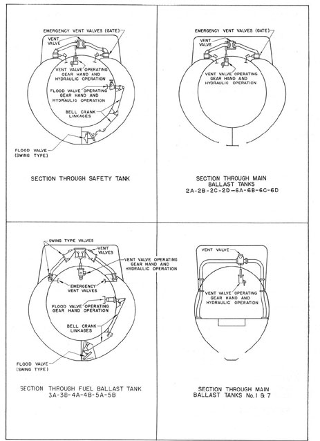
All main ballast tanks have hydraulically operated vent valves which can be rigged for hand
operation. Each tank has a vent riser extending from the top of the tank to the superstructure on
the ship's
44
4-1 Venting and flooding arrangement.
45
centerline. All main ballast tanks, except MBT No. 1 and No. 7, have emergency vent valves located at
the tank top, with stems for hand operation extending through and into the pressure hull, to act as
an emergency stop valve if the main vent valves or risers are damaged. (See Figure 4-2.)
Sea water is admitted to each ballast tank through flood ports, located in the bottom of the
tanks near the keel. They are rectangular in shape.
The main ballast tanks are blown with 600-pound air through the 600-pound manifold or with
10-pound air from the low-pressure blower through the 10-pound blow manifold. The low-pressure blower is used only after the ship has surfaced.
Each main ballast tank is provided with a salvage air connection which permits blowing the
tank from the outside of the hull during salvage operations. Air for such an operation is furnished
by a salvage ship through a hose.
D. VARIABLE BALLAST TANKS
4D1. Name and location. There are six variable tanks named and located as follows:
1. Forward trim tank - inside pressure hull
2. Forward WRT tank - inside pressure hull
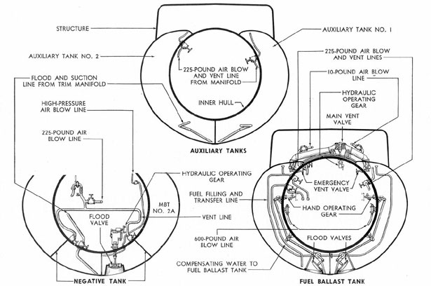
3. Auxiliary tank No. 1 - outside pressure hull
4. Auxiliary tank No. 2 - outside pressure hull
5. After WRT tank - inside pressure hull
6. After trim tank - inside pressure hull
The general location and shape of each of the variable tanks are shown in FigureA-5.
4D2. Function. The variable ballast tanks are used in conjunction with the trim system to
maintain the trim of the submarine. Secondary function of the WRT tanks is to receive water
drained from the torpedo tubes and to furnish water for flooding the tubes prior to firing
operations.
There are no direct sea connections provided for the variable tanks. All pumping and
flooding of these tanks must be done through the trim manifold and the lines of the trim system.
The WRT tanks and the trim tanks can be flooded through the torpedo tubes. Blowing and
venting of the variable tanks are accomplished by the 225-pound service air system, through the
225-pound manifold, and the torpedo tube blow and vent manifold.
E. SPECIAL BALLAST TANKS
4E1. Safety tank. The primary function of the safety tank is to provide a means for
quickly regaining positive buoyancy by blowing the tank when submerged. It follows, then, that
the safety tank must be fully flooded when submerged, otherwise it cannot fulfill its primary
purpose. For this reason, in the design of the tank arrangements, the safety tank has been located
so that it has little or no effect on fore-and-aft trim when fully flooded or when blown dry.
The safety tank is located amidships between fuel ballast tanks 3A and 3B and auxiliary
ballast tanks No. 1 and No. 2 between
the pressure and outer hulls. (See FigureA-6.) It extends from port to starboard. Since the
flooded weight of the safety tank ballast is approximately equal to the weight of water in a
flooded conning tower, the safety tank may be blown to compensate for a flooded conning tower.
The safety tank is provided with two flood valves, normally operated hydraulically from the
control room, with provisions made for hand operation. Indicator lights, operated by a contact at
the valves, show whether the safety tank flood valves are opened or shut. These valves open
outboard and seat with sea pressure.
46
Figure 4-2. Tank connections.
47
One vent valve, with risers located on both the port and starboard sides, is provided for the
safety tank. This vent valve is operated hydraulically from the control room, or locally by hand.
The emergency vent valves provided for the safety tank are located port and starboard at the
tank top, and are gate type valves, with the gates traveling on the threaded operated stem.
The inboard vents for the safety tank are operated manually from the crew's mess room.
These vents located at both the port and starboard sides of the tank connect through a T to one
common outlet in the control room. Therefore, when the safety tank is vented inboard, the vented
air is bled into the control room proper.
The safety tank is blown by the 3,000-pound air system through the high-pressure
distributing manifold in the control room. Like the pressure hull, the safety tank is heavily
constructed to withstand full submergence pressure. It is also connected to the trim system and
can be used as a variable ballast tank.
4E2. Negative tank. The negative tank, located inside MBT No. 2A and No. 2B, is used
to provide negative buoyancy for quick diving.
It is provided with a flood valve which is normally operated hydraulically from the
control room, but can be operated locally by hand. This valve opens against sea pressure. The
tank vents inboard through a quick-opening manually operated valve located in the control room.
(See Figure 4-1.)
The tank is blown through the negative tank blow valve on the high-pressure distribution
manifold. It can also be blown with the 225-pound system.
The negative tank is built to withstand full submergence pressure and can be used as a
variable tank and pumped through the lines of the trimming system.
4E3. Bow buoyancy tank. The bow buoyancy tank is located at the bow of the
submarine in the foremost section of the superstructure, as shown in Figure
A-6. It is used to
correct excessive down angles and to give the ship an up angle during surfacing.
The bow buoyancy tank is free flooding through ports in the superstructure plating along the
outside boundary of the tank.
It is provided with two interconnected vent valves which are equipped for hydraulic or hand
operation and are controlled by a single operating gear in the forward torpedo room.
The tank outboard vent is protected by a grating in the superstructure deck. The bow
buoyancy tank is blown directly with high-pressure air from the 3,000-pound air system.
F. FUEL BALLAST TANKS
4F1. General. There are three fuel ballast tanks, identified as FBT 3A and 3B, FBT 4A
and 4B, and FBT 5A and 5B. All A tanks are located on the starboard side; all B tanks are on the
port side. The primary function of these tanks is to carry ballast, hence they are considered as
ballast tanks. However, the secondary function, which is almost as important as their primary
function, is to carry reserve fuel oil. In any case, they serve as ballast tanks, since they must be
completely full to submerge. With the demand for extended submarine patrols, these tanks are
usually filled with fuel oil and become water
ballast tanks only when they fuel is expended.
The fuel ballast tanks are located between the pressure and outer hulls. (See FiguresA-4
andA-7.) The A and B tanks are connected through limber holes cut in the vertical keel to permit the
flow of ballast between tanks.
All fuel ballast tanks have hydraulically operated vent valves which can be rigged for
hand operation. Each tank has a vent riser extending from the top of the tank in the
superstructure on the ship's centerline. All fuel ballast tanks have emergency vent valves located
at the tank top, with stems for hand
48
Figure 4-3. Tank arrangement.
49
operation extending through and into the pressure hull. These valves serve as stops and enable
the tank to be blown if the main vent valves or risers are damaged. (See Figure 4-2.)
Sea water can be admitted to each fuel ballast tank when used as main ballast tanks, through
flood valves located in the bottom of the tank near the keel. They are rectangular in shape and
open inboard. The fuel ballast tanks are provided with hand-operated flood valves.
When the fuel ballast tanks are used as fuel tanks, the flood valves are locked shut, the vents
disconnected, and a special plate bolted across the vent opening in the superstructure. The fuel
ballast tanks are connected to the fuel system, to the compensating water system, and to the 225-pound air system. (See Figure 4-2.)
The fuel ballast tanks, when used as main ballast tanks, are blown with 600-pound air
through the 600-pound manifold or with 10-pound air from the low-pressure blower through the
10-pound blow manifold.
G. ADDITIONAL TANKS
4G1. Normal fuel oil tanks. There are four normal fuel oil tanks for the storage of oil for
the ship's engines. They are located between the inner and outer hull as shown in Figure
A-7.
These tanks are known as normal fuel oil tanks (NFOT) Nos. 1, 2, 6 and 7.
Each tank has connections for filling, transferring, and admitting compensation water to
replace expended oil, and connections to the 225-pound air system.
Water from the compensating water system is admitted to each fuel tank to compensate for
expended fuel oil, or for changes in the volume of fuel oil caused by variations in temperature,
thereby keeping the tanks always full of liquid. The fuel tanks are open to sea pressure through
the compensating system when submerged.
Try cocks extending into the pressure hull indicate the liquid content of the tank.
4G2. Collecting and expansion tanks. The fuel oil collecting tank, located on the
starboard side between MBT 6C and NFOT No. 6, is used as a settling tank, separating oil and
water in the compensating system to provide a source of oil for the fuel pump. (See
FigureA-7.)
The expansion tank, located on the port side between MBT 6D and NFOT No. 6, is used as
an overflow tank when the fuel
volume expands because of temperature variation, and to supply water to the compensating water
system. It may also be used to receive bilge water.
Both the expansion and collecting tanks are located between the pressure and outer hull.
4G3. Clean fuel oil tanks. The No. 1 and No. 2 clean fuel oil tanks are located inside the
pressure hull; No. 1 is in the after part of the forward engine room, No. 2 is in the after part of the
after engine room. Their purpose is to provide main fuel pump suction and to store purified oil.
4G4. The lubricating oil tanks. There are ten lubricating oil tanks, divided into four
groups as shown in the following table.
The three normal lubricating oil tanks are used for storage of lubricating oil, as is the reserve lubricating oil tank. The tanks are provided with
vents, air connections to the 225-pound air system, and reducing valves set to deliver air at 13
pounds pressure from the 225-pound service lines. Oil may be blown from any storage tank to
any other tank, or discharged overboard, through the lines and manifold of the lubricating system.
The tanks are filled from an outside source by means of a filling connection located on the
superstructure deck.
50
TANK
LOCATION*
Normal lubricating oil group:
Normal lubricating oil tank No. 1
Forward engine room
Normal lubricating oil tank No. 2
After engine room
Normal lubricating oil tank No. 3
Inside MBT No. 7
Reserve lubricating oil group:
After part, portside after
Reserve lubricating oil tank
battery compartment
Main engine sump group:
Main engine No. 1 oil sump
Forward engine room
Main engine No. 2 oil sump
Forward engine room
Main engine No. 3 oil sump
After engine room
Main engine No. 4 oil sump
After engine room
Reduction gear sump group:
Reduction gear oil sump No. 1
Outside pressure hull, inside NFOT No. 7 starboard of centerline
Reduction gear oil sump No. 2
Outside pressure hull, inside NFOT No. 7 port of centerline
*The location of each of these ten oil tanks is shown in
FigureA-7.
4G5. Fresh water tanks. There are four fresh water tanks. Nos. 1 and 2 are forward of
the forward battery compartment, inside the pressure hull. Tanks Nos. 3 and 4 are located in the
after part of the control room. (See FigureA-3.) These tanks are used to store the ship's fresh
water supply.
There are five emergency fresh water tanks, located one each in the after torpedo room,
maneuvering room, control room, and two in the forward torpedo room. The tanks in the
forward torpedo room and the one in the after torpedo room can be filled directly from the fresh
water system; the other tanks must be filled by portable means.
4G6. Battery water tanks. There are eight battery water tanks used to store the ship's
battery water. These tanks are located as follows:
Tanks Nos. 1, 2, 3, and 4-
Forward battery space
Tanks Nos, 5, 6, 7, and 8-
After battery space
These are referred to as the forward group (1, 2, 3, and 4), and the after group
(5, 6, 7, and 8). (See FigureA-8.)
4G7. Sanitary tanks. There are two sanitary tanks, No. 1 located inside MBT No. 1, and
No. 2 located inside the pressure hull in the after starboard end of the after battery compartment.
The purpose of these tanks is to collect drain water and refuse from the ship's sanitary system.
The No. 1 sanitary tank is connected with the officer's head, while No. 2 sanitary tank is
connected with the crew's head in the after battery compartment. (See FigureA-5.)
4G8. Miscellaneous tanks. There are also a number of smaller tanks for special usage.
The following table gives the names and locations of these tanks: