11A1. Importance of the air systems to submarines. The importance of the air systems
to a submarine cannot be overemphasized,
for virtually every function in the diving and
surfacing procedure stems initially from air
provided by one or more of the air system;
to cite a few:
a. The main hydraulic system operates
because of the air pressure maintained in the
air-accumulator flask.
b. Torpedoes are discharged from the
submarine by air.
c. Tanks are blown by air.
d. The main propulsion engines are
started by air.
Air, or more specifically, compressed air,
is necessary to surface, submerge, attack, and
cruise. In addition, compressed air together
with oxygen is used to revitalize the air in
the ship after long periods of submergence.
Pressure in the boat, a test for tightness,
utilizes air.
The air systems represent, therefore, the
most versatile of all systems aboard a submarine, in that they are capable of performing, either as primary or secondary functions,
more operations than any other single
system.
11A2. Basic principles of compressed air.
The actuating force of the air systems is compressed air, which, as the name implies, is
air under pressure confined within the limits
of a container. The force required for compression of the air is provided by the high-pressure air compressors, a simple machine
that compresses air by means of a series of
pistons designed so that one or more pistons
discharges air into another for further compression and finally through lines to banks
for storage. Air can be compressed easily
aboard a submarine, as it requires a relatively small plant and comparatively simple
equipment. It can be stored at any convenient
place and is always ready for use. Its action
can be regulated to produce a low or high-pressure, and yet it has enough elasticity or
compressibility to cushion its impact against
the equipment it operates. It consumes no
valuable materials and can be supplied to any
part of the submarine simply by extending a
line from the air supply. Air, once stored,
requires no further expenditure of energy for
operation, but rather is a source of power to
other equipment.
B. TYPES AND RELATIONSHIPS OF AIR SYSTEMS
11B1. General information. There are five
air systems on the submarine: the 3,000 pound high-pressure and torpedo impulse
system; the 600-pound main ballast tank
(MBT) blowing system; the 225-pound service air system (ship's service air); the 10-pound main ballast tank (MBT) blowing
system; and finally, the salvage air system.
(See FigureA-13.)
The 600-pound MBT blowing system and
the 225-pound service air system receive their
supply of air from the 3,000-pound air system. The 10-pound MBT blowing system is
an independent system with its own low-pressure blower. The internal compartment
salvage air system is dependent upon the
225-pound service air system, while the external compartment salvage air system is
entirely dependent upon an outside source for
its supply of air.
11B2. The 3,000-pound and torpedo tube impulse air system. This system consists of the 3,000-pound high-pressure compressors, the
high-pressure manifold, the interconnecting
piping, valves, and compressed air banks. The
main function of the 3,000-pound air system
is to compress, store and supply air at the
maximum pressure of 3,000 pounds per
square inch for use within the 3,000-pound,
the 600-pound, and the 225-pound systems.
122
The 3,000-pound air system also supplies
air to the hydraulic accumulator air loading
manifold and to the forward and after 600
pound Grove reducing valves which supply
the forward and after torpedo tube impulse
charging manifolds.
The 3,000-pound air system is equipped
with air external charging connection so that
the system may be supplied with air from an
outside source.
11B3. The 600-pound MBT blowing system.
The only function of the 600-pound MBT
blowing manifold and system is to remove
water ballast front the main ballast tanks or
the fuel ballast tanks when used as main ballast tanks. It receives its supply of compressed air from the high-pressure system
through the distributing manifold.
11B4. The 225-pound service air system. The
225-pound service air system or, as it is
sometimes called, ship's service air, is so
called because, in addition to blowing the
variable group of tanks, it provides the compressed air for all the miscellaneous services
aboard the submarine. The 225-pound system
consists of the 225-pound service air manifold, interconnecting piping, and various
valves.
11B5. The 10-pound MBT blowing system.
When the submarine has surfaced, the 10-pound main ballast tank blowing system is
used to conserve the compressed air stored
in the ship's air banks. The system consists
of its own low-pressure blower, control manifold, and piping to the various main ballast
tanks. The 10-pound system is operated only
after the submarine has, surfaced sufficiently
to permit the opening of induction valves and
hatches.
11B6. The salvage air system. This system is actually three separate systems: the
MBT external salvage, the compartment external salvage, and compartment internal
salvage. The external salvage connections
permit compressed air from an outside source
to be supplied to the tanks and/or compartments, while the internal salvage system
utilizes the ship's air for, compartment salvage only.
C. HIGH-PRESSURE AIR AND TORPEDO IMPULSE AIR SYSTEMS
11C1. General description. FigureA-14
shows the location and relationship of the
individual units that comprise the high-pressure 3,000-pound air system. It should be
noted that 3,000 pounds is the maximum
working pressure of the system end not a
constant pressure. Actually, the pressure may
vary between 1,500 and 3,000 psi. The system
is hydrostatically tested to 4,500 psi or 150
percent of the working pressure. The system
extends from the high-pressure air compressors in the pump room to the receiving and
distributing manifolds in the control room,
and from there forward to the torpedo impulse air system in the forward torpedo room,
athwartship to the air banks, and aft to the
after torpedo room.
In Sections 11C1 through 11C4, a more
detailed description is given of the general
layout of the high-pressure air system. The
control room, the air banks, and the torpedo
impulse air system fore and aft of the control
room are discussed.
11C2. Manifolds and lines. The high-pressure
manifold, made up of a receiving manifold
and two distributing manifolds, is mounted
on the starboard side of the control room.
The receiving manifold receives air up to
3,000 psi from two high-pressure air compressors, and directs it to the air banks where
it is stored. The capacity of each compressor is 20 cubic feet per hour at 3,000 psi. As
the air is needed, it flows back through the
same piping to the receiving manifold where
it is directed to the distributing manifold.
This operation is controlled by the valves on
the manifold.
The 3,000-pound service air lines supply
air at a pressure up to 3,000 psi to the forward and after torpedo rooms, to the engine
starting flasks, and to the reducing valves in
each engine room which furnish 500-pound
air used in starting the diesel engines.
The distributing manifolds distribute air
to the safety and negative tank blow lines,
the main ballast tanks blow manifold, the
123
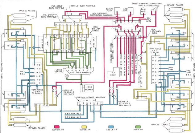
Figure 11-1. Compressed air systems.
124
hydraulic accumulator air flask, the high-pressure air bleeder, the bow buoyancy tank
blow line, the 225-pound service air system,
and the forward and after 3,000-pound service air lines.
11C3. Air banks. Each of the five air banks
consists of seven flasks, with the exception of
the No. 1 air bank which has eight. Each
flask is provided with a drain valve. The
total capacity of the air banks is 560 cubic
feet.
The No. 1 air bank is located inside the
pressure hull, with four flasks in each battery,
compartment. The other four air banks are
located in the main ballast tanks. (See FigureA-14.)
11C4. Torpedo impulse air system. The torpedo impulse air system stores and controls
the air used to discharge the torpedoes from
the tubes.
The 3,000-pound air service line forward,
extending from the distributing manifold,
ends with a 3,000-pound to 600-pound reducing valve, from which a line leads to the
forward torpedo impulse air system. This
system is composed of two impulse flask
charging manifolds and six impulse flasks
connected by lines to the manifolds. The
impulse flasks are mounted above the pressure hull in the superstructure forward. One
impulse flask charging manifold is located on
the port side of the torpedo room and the
other on the starboard side. Each manifold
is used to charge three flasks with 600-pound
air.
The 3,000-pound air service line aft, extending from the distributing manifold, ends
with a 3,000-pound to 600-pound reducing
valve, through which air is furnished to the
after torpedo impulse air system. This system consists of one impulse flask charging
manifold with lines leading to the four impulse flasks provided for the four after torpedo tubes. The impulse flasks are mounted
below the after torpedo room deck; the manifold is located on the starboard side.
In both the forward and the after sections of the torpedo impulse system, a bypass
valve and line are provided, leading from the
3,000-pound air service line to the charging
manifold. The bypass valve and line allow
the charging of the impulse flasks in the
event of failure of the reducing valves.
D. THE 600-POUND MAIN BALLAST TANK BLOWING SYSTEM
11D1. General description. The main ballast
tanks are filled with sea water when the submarine is submerged. These tanks cannot
be pumped. Therefore, when the submarine
is surfacing, compressed air must be used to
blow the water out through the flood ports to
the sea.
Two separate systems are provided to
blow the main ballast tanks. This section describes the first of these, the 600-pound MBT
(main ballast tank) blowing system. The
second system, the 10-pound MBT blowing
system, is used only when the ship is surfaced.
FigureA-15 shows the location of the
lines and component parts of the 600-pound
MBT blowing system. The system is inside
the pressure hull and extends from the MBT
blowing manifold in the control room fore
and aft along the starboard side to the main
ballast tanks and fuel ballast tanks.
The MBT blowing manifold is the
distribution control unit of the system. It is
located on the starboard side of the control
room with its pressure gage next to it. The
piping mounted directly above the manifold
connects the MBT blowing manifold with the
high-pressure air manifold through two hammer valves.
The maximum working pressure of the
600-pound main ballast tank blowing system
is 600 psi. It is tested hydrostatically to a
pressure of 1,000 psi, or 166 percent of the
maximum working pressure.
Air at bank pressure (1,500 to 3,000 psi)
passed through two manually operated hammer valves and two group stop check valves
to the 600-pound MBT blowing manifold.
The flow of the air is regulated by the hammer valves so that it is delivered at the required pressure. Normally, only one hammer
valve is used for blowing; in case one does
not supply enough air or in case of failure,
the other hammer valve can be used. The
125
group stop check valves permit the blowing
of tanks by groups. The manifold is protected by a sentinel valve and two relief
valves set to blow when the pressure in the
600-pound system reaches 750 psi. A sentinel
valve is set to blow at a pressure of 610 psi.
When the sentinel valve opens, it acts as a
relief valve for comparatively small rises in
pressure and gives notice of excessive pressure in the system.
To supply air to the 600-pound MBT
blowing system, one of the hammer valves is
opened. The valve permits air from the 3,000
pound manifold to enter the MBT blow manifold at a reduced pressure. The pressure
gage of the MBT blow manifold is closely
watched to guard against the pressure exceeding 600 pounds.
The depth at which the submarine is
operating will have a direct effect on the
resistance offered to the air in blowing the
main ballast tanks and, therefore, the pressure will be built up within the system more
rapidly at greater depths than it will on the,
surface. Since the hammer valve regulates
the volume of the air entering the 600-pound
MBT blowing system, while the resistance
offered to this air varies with submerged
depth, it follows that, when submerged at
great depths, the hammer valve must be
opened cautiously, otherwise the pressure
within the system will build up rapidly and
exceed the safe working pressure. When the
gage indicates that the pressure is dropping,
the hammer valve is opened wider to
maintain the required pressure. When blowing is
finished, the hammer valve is shut.
Blow lines extend from the forward section of the 600-pound MBT blow manifold to
tanks No. 1 MBT, Nos. 2B and 2D MBT.
Nos. 2A and 2C MBT, and Nos. 3A and 3B
FBT. From the after section of the manifold, blow lines extend to tanks Nos. 4A and
4B FBT, Nos. 5A and 5B FBT, Nos. 6B and
6D MBT, Nos. 6A and 6C MBT, and No. 7
MBT. Any tank or any combination of tanks
can be blown by opening the required individual tank valve, or valves, the group valves,
and finally the hammer valves.
When the submarine is rigged for diving, all the blow valves on the manifold,
except the fuel ballast tanks valves, are open,
as are the two group stop check valves. The
individual regulator valves at the main ballast tanks are open, while the MBT blow
hammer valves on the 600-pound manifold
are shut. The two supply valves to the 600-pound MBT blow manifold on the distributing
manifold are open.
To operate the 600-pound MBT blow
system, the hammer valve is opened and air
is admitted to the blow manifold, from which
it is directed to the main ballast tanks by
the lines of the system.
Each blow line is provided with a regulator valve at the point where it enters the
tank. The regulator valve acts as a combination stop and check valve and is equipped
for securing the stop in any position required
to equalize the flow of air into the tanks.
E. THE 225-POUND AIR SYSTEM (SHIP'S SERVICE AIR)
11E1. General description. The 225-pound
service air system, known as the ship's service air system, performs or controls many operations other than those discussed in the
sections dealing with the 3,000-pound, the
torpedo impulse, and the 600-pound air systems. The 225-pound air system provides the
air for approximately 100 operations. The
system extends from the forward torpedo
room to the after torpedo room, with service
connections in every compartment of the
vessel, and supplies air at pressure ranging.
from 225 psi to 8 psi. The center of direction
of the system, the 225-pound service air manifold, is located in the control room. The 225-pound system is hydrostatically tested to 350
psi, or 155 percent of its maximum working
pressure of 225 psi.
FigureA-16 shows the, location and relationship of the parts of the system, as well
as their nomenclature.
The discussion of the ship's service air
system starts with the control room, describing each component part of the system
located there, and explaining its function in
the operation of the submarine. A similar
126
procedure is followed for each of the compartments of the vessel, proceeding first forward and then aft of the control room.
11E2. Control room. The 225-pound service
air manifold is located in the control room
on the starboard side aft of the high-pressure
manifold. This manifold receives its supply
of air through two Grove pressure-reducing
valves which reduce the high-pressure air
from 3,000 psi to 225 psi. Stop valves are
provided on the low-pressure side of the 225-pound Grove reducers, cutting them off the
225-pound system. This permits removal of
a Grove reducer without impairing the operation of the 225-pound system. The 225-pound
service air manifold can also be supplied from
the 225-pound bypass which is controlled by
a manually operated 225-pound bypass valve
located at the high-pressure distribution manifold. Where the 225-pound bypass is used,
the high-pressure air bypasses the reducing
valves and is admitted directly into the 225-pound system. The bypass valve is only partly opened so that the pressure can be built up
gradually. The 225-pound manifold pressure
gage must be constantly watched and the
pressure must never be allowed to go beyond
225 psi.
The 225-pound service air system is protected by one sentinel valve and two relief
valves located on the line between the Grove
reducers and the 225-pound manifold.
When the air within the 225-pound system reaches a pressure of approximately 250
psi, the sentinel valve opens, allowing the
excess air to escape into the compartment.
The sentinel valve has a comparatively
small capacity and serves primarily to warn
that the normal working pressure is exceeded.
If the rise in pressure is rapid and above the
capacity of the sentinel valve, the two relief
valves, set to operate at 275 psi, open and
allow the excess air to escape into the compartment.
The relief valves and the sentinel valve
shut automatically when the normal working
pressure is restored.
The supply line from the Grove reducing
valves has two branches. One branch
supplies 225-psi and air to the hydraulic oil supply
volume tank, the signal ejector, the drain
pump air domes, the negative tank blow
valve, and the sea pressure and depth gage
blows.
The other branch of the line from the
Grove reducing valves supplies air to the
225-pound service air manifold. This air is
directed by means of valves to the forward
and after service air mains, the auxiliary tank
blow and vent lines, and the forward and
after trim tank blow and vent lines. A hose
connection to the manifold provides for air
supply from the shore or tender.
A reducing valve from the forward service air main furnishes air at pressure of
100 psi to a connection for pneumatic tools.
A bypass is provided for emergency operations, with a relief valve set to open at a
pressure of 110 psi as a protection against
excessive pressure. It also carries a connection supplying air to the whistle and siren.
The after service main has branch connections to the sea pressure gage and to the
compartment air salvage. It also supplies
air through a reducing valve at a pressure
of 12 psi to fresh water tanks No. 3 and
No. 4. A bypass is provided for emergency
operation, with a relief valve set to open at
a pressure of 15 psi.
11E3. Forward battery compartment. In the
officers' quarters, the forward service air
main supplies the compartment air salvage
valve mounted on the after bulkhead. This
valve can be operated from either side of the
bulkhead. A branch of the service line, passing through an 8-pound reducing valve, supplies air at a pressure of 8 psi to the four
battery water tanks Nos. 1, 2, 3, and 4 in
the forward battery compartment. A bypass
line is provided for emergency operation, with
a relief valve set to open at a pressure of
10 psi.
11E4. Forward torpedo room. In the forward torpedo room, the forward service air
main extends to the torpedo tube blow and
vent manifold. The service main is also provided with branch lines to the torpedo stop
cylinders, the escape trunk blow, the volume
127
tank, the sanitary tank, the QC and JK sea
chests, the underwater log, the compartment
air salvage valve, and the fuel oil blow and
vent manifold. Two other branch lines,
equipped with reducing valves and bypass
lines, furnish air to the pneumatic tool connection at 100 psi, and to the No. 1 and
No. 2 fresh water tanks at 12 psi. The line
to the escape trunk supplies air for the ship's
diver's air, connection, and a blow and vent
line for the escape chamber. The forward
trim tank blow and vent line from the 225-pound manifold in the control room terminates at the forward trim tank and connects
with the forward trim tank blow and vent
line from the forward torpedo tube blow and
vent manifold.
11E5. After battery compartment. The galley and mess room compartment has one connection from the after service main which
supplies air to the blow and vent manifold for fuel ballast tanks 3A, 3B, 4A, and 4B. A
second connection enters an 8-pound reducing
valve and supplies air at 8 psi to the four
battery fresh water tanks Nos. 5, 6, 7, and 8
located in the after battery compartment.
Bypass is provided for emergency use with a
relief valve set to open at 10 psi. The lines
for blowing and venting the auxiliary ballast
tanks connect from the 225-pound manifold
to the auxiliary ballast tank and stop valves
located at the tank top in this compartment.
11E6. Crew's quarters. In the crew's quarters, the after service main supplies air to
the crew's forward water closet and the
No. 2 sanitary tank blow line. The sanitary
tank is equipped with a relief valve set to
open at 105 psi.
11E7. Forward engine room. The forward
engine room has direct connecting lines from
the after service main to the compartment
air salvage valve, the No. 5A and No. 5B
fuel ballast tank manifold, the exhaust valve
operating gear, and the lubricating oil tanks
blow and vent manifold. The supply to the
fuel oil manifold is protected by a relief valve
set to open when the pressure exceeds 15 psi.
The air for the lubricating oil manifold is
reduced to 13 psi by a reducing valve. A
bypass is provided for emergency operation,
with a relief valve set to open at 15 psi. In
addition, the forward engine room is provided with a pneumatic tool connection
equipped with a 100-pound reducing valve and
a bypass for emergency. A relief valve, set
to open at 110 pounds, safeguards the line
against excessive pressure.
11E8. After engine room. In the after engine room, the after service main has direct
connections to the compartment air salvage
valve, the auxiliary engine shutdown, and the
air manifold which controls the blowing and
venting of the Nos. 6 and 7 normal fuel oil
tanks, the expansion and the collecting tanks.
A relief valve, set to open at 15 psi, protects
No. 6 and No. 7 normal fuel oil tanks and
the collecting and expansion tanks against
excessive internal pressure. A pneumatic tool
connection is also provided, equipped with a
100-pound reducing valve, 110-pound relief
valve, and a bypass line, to supply air at
100 psi.
11E9. Maneuvering room. The maneuvering
room contains lines extending from the after
service main to the after water closet, the
compartment air salvage valve, and the main
engine shutdown connection.
11E10. After torpedo room. In the after torpedo room, the service air main has branches
leading to the 225-pound compartment air
supply valve for escape hatch, the torpedo
tube stop cylinders, the volume tank, and the
pneumatic tool connection. The pneumatic
tool connection is provided with a 100-pound
reducing valve and a bypass protected by a
110-pound relief valve. The service air lines
terminate at the after torpedo tube blow and
vent manifold.
The after trim tank blow and vent line,
which extends from the 225-pound manifold
in the control room, connects with the after
trim tank by a branch line extending to the
torpedo tube blow and vent manifold, similar
to that of the forward torpedo room.
The compartment air salvage valves are
so mounted on the transverse bulkheads of
each compartment that they may be operated
from either side, releasing air into the compartment from which they are worked, or
into the adjoining compartment. The compartment air pressure gages are also mounted
128
on either side of the bulkheads to permit a
reading of air pressure in the adjoining compartment.
All manifolds and lines equipped with
reducing valves and blow valves are provided
with pressure gages. All fuel oil, lubricating
oil, collecting, expansion, sanitary, and variable tanks are provided with pressure gages
located in the various rooms and compartments.
F. THE 10-POUND MAIN BALLAST TANK BLOWING SYSTEM
11F1. General description. The 10-pound
MBT blowing system is used to remove water
from the main ballast tanks when the submarine is on the surface. It completes the
work started by the 600-pound MBT blowing
system, thus saving high-pressure air.
The 10-pound MBT system (FigureA-17)
consists of a low-pressure blower located in
the pump room, a manifold, and blow lines
to each of the tanks serviced by the system.
The low-pressure blower furnishes compressed air to the manifold in the control
room at a pressure of approximately 10 psi.
The manifold distributes the air supplied by
the blower to the ballast tanks through nine
pipe lines which pass through the hull directly
above the manifold and extend outside the
pressure hull under the superstructure deck.
The air supply to the manifold is controlled by the flapper valve. The manifold
and the valves are designed to withstand sea
pressure if any of the blow lines fail.
The nine low-pressure lines have lever-operated flapper valves (10-pound blow
valves) at the point where they pass through
the hull, and swing check valves where they
join the main ballast tank (MBT) vent risers.
Gate valves, controlled from the superstructure deck, are installed in the lines leading to main ballast tanks 2A, 2B, 2C, 2D, 6A,
6B, 6C, and 6D.
The list control dampers are used to
correct a list during blowing of the main
ballast tanks. The list control dampers adjust the amount of air admitted into the port
or starboard ballast tanks of the No. 2 and
No. 6 MBT group, increasing or decreasing
the rate at which the tank is blown. The
dampers are located at the Y outlet connections on the 10-pound blow manifold.
Both list dampers are attached to a shaft
which runs through the manifold chamber.
The shaft is operated by a hand lever at the
after end of the manifold. The handle assembly consists of a push rod at the top of
the handle, a handle, a spring, a latch, a
name plate, and a bracket. Pressing down
the push rod releases the spring, lifting the
latch, and leaving the lever free to move inboard or outboard. As the shaft turns, the
list dampers are swung to shut one port or
open both ports of the Y.
The movement of the lever and the attached connecting rod turns the shaft by
means of an offset arm. Outboard movement
of the lever causes the damper to restrict the
flow of air to the starboard side. Inboard
movement of the lever causes the damper to
restrict the flow of air to the port side. The
normal position of the damper is neutral,
allowing equal flow to both sides.
G. SALVAGE AIR SYSTEM
11G1. General description. The submarine
is provided with a salvage air system for use,
in salvage operations.
The salvage air arrangements provide
external salvage facilities for use by outside
salvage agencies (divers, and so forth) and
also internal facilities for use by the crew
of the submarine or by a diver, after he succeeds in entering the vessel.
FigureA-18 shows in schematic form
the location and relation of the component
parts that comprise the salvage air system.
Two external high-pressure air connections, located on each side of the conning
tower, provide a means of supplying high-pressure air from the salvage ship to the
high-pressure (3,000-pound) receiving manifold. This air can be directed by personnel
129
COMPARTMENT SALVAGE DECK PLATE MARKINGS *
Compartment
Number of Screw Heads
HIGH CONNECTION
LOW CONNECTION
Officers' quarters
1
2
Forward torpedo and control room
3
4
Crew's quarters
5
6
Forward engine room
7
8
After engine room
9
10
Maneuvering room
11
12
After torpedo room
13
14
TANK SALVAGE DECK PLATE MARKINGS
Tank
Number of Lugs
MBT 2A and 2B
1
MBT 1
2
MBT 2C and 2D
2
MBT 6A and 6B
3
MBT 6C and 6D
4
MBT 7
5
10-POUND DECK PLATE BLOW MARKING
Tank
Number of Lugs
MBT 2A and 2B
2
MBT 2C and 2D
4
MBT 6A and 6B
6
MBT 6C and 6D
8
* The markings used for a particular submarine may be obtained from the vessel's air salvage systems plans.
130
inside the vessel to the 600-pound blow manifold for use in blowing the main ballast tanks.
and to the 225-pound service air manifold
for use in blowing water from flooded compartments by means of the compartment salvage air valves.
Each main ballast tank has an external
salvage valve with a blow line connection
extending up to a plate set in the deck. In
salvaging, air hose lines from the salvage
ship are attached to the pipe fitting and the
valve is opened, thus enabling the rescue
vessel to blow the ballast tanks free of water.
Each compartment of the submarine has
two external compartment salvage valves, one
at either end of the compartment. A salvage
line from each valve extends through the hull
to a deck plate where it is provided with a
capped male fitting, similar to those of the
main ballast tank salvage lines. The valve
can be operated by a socket wrench from the
outside or by a handwheel from within the
compartment. In salvaging operations, air
hoses can be attached to the valve fittings to
supply the ship with air for breathing, pumping, or circulating purposes.
Compartment salvage air valves are
located on each bulkhead between compartments, for use in blowing individual compartments. The 225-pound air is supplied to
these compartment salvage air valves by lines
extending from the forward and after service
air lines. The arrangement of the valves permits the release of air from either side of the
bulkhead into the adjacent compartment.
Pressure gages are installed on both sides
of the bulkhead near this valve arrangement
to indicate the pressure in the adjoining compartment.
All external salvage valve deck plates
are identified by lettering and round screw heads, and special lugs cast on the plates for
touch identification.