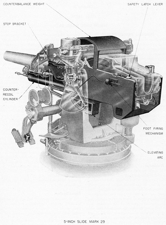
1. The Slide Mark 29, is a large box-shaped steel weldment, pivoted horizontally on trunnions which are supported in roller bearings in the carriage assembly described in chapter 4. Trunnion clips serve to support, and provide a pivot for, the sight assembly described in chapter 8. The arrangement supports the gun assembly and the recoil and counterrecoil cylinders; and includes elements of the breech operating mechanism, the elevating arc, and parts of the firing mechanism. Plate 12 illustrates the slide and attached devices with the rest of the mount shown in phantom.
2. Components. The slide is an assembly of the following parts or subassemblies described in the. sequence below:
Slide weldment
Recoil system
Counterrecoil system
Breech mechanism elements
Housing guides
Elevating arc
Counterbalance weight
Certain elements of the firing mechanism form a part of the slide assembly. They are described in conjunction with the mechanism as a whole in paragraphs 17 to 19, inclusive, of this chapter.
Slide Weldment
3. The main element of the slide (pl. 12) is a 1250-pound, box-shaped steel weldment enclosed at the sides and part of the bottom. An arc-shaped transverse support bracket is bolted to the inside faces of the side plates of the slide for rigidity. Two trunnions, one on each side near the front of the unit and integral with it, form the carriage bearing journals. The lower portion of the weldment has three bored holes through the two transverse vertical plates to form a support for the recoil and counterrecoil cylinders. The bottom of this section has a milled transverse keyway and drilled holes for attachment of the elevating arc bracket (fig. 8). A lug on the front end of the right side plate
forms a positive stop for the slide in depression by coming in contact with a machined lug on the carriage cheek. This stop does not usually function; the training-and-depression stop described in chapter 4 normally stops depression ahead of it. A machined surface on the transverse rear member of the slide comes in contact with a similar surface at the bottom of the carriage to form a positive stop in elevation. A brass arc-shaped plate, called the elevation indicator arc, is stamped in degrees from 10° depression to 40° elevation. It is mounted on the outside of the left side plate in line with a pointer on the carriage to indicate gun elevation angle.* Two lugs welded on the inside of the side plates form positive stops to locate the gun in the battery position. As the gun is brought to rest in counterrecoil movement by the buffing action of the recoil cylinder, the counterrecoil springs force the housing against these stops and hold it there. Trunnion clips bolted to the ends of the trunnions form supports and pivots for the sight mechanism. A pad on the top of each side plate is provided for attachment of gear racks on which the sight moves relative to the slide in setting the sight angle. Longitudinal slots in the side plates, just below the centerline of the trunnions, receive the bearing strips on which the guide rails of the gun-and-housing assembly ride in recoil and counterrecoil. A stop bracket, bolted to the left side of the slide near the front, functions as part of the training and depression stop mechanism described in paragraph 8, chapter 4.
Recoil System
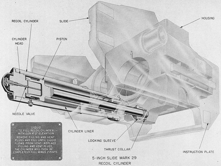
4. The recoil system (pl. 13) is a self-contained hydraulic assembly comprising a cylinder, cylinder liner, piston with integral piston rod, and thrust collar, with necessary bushings, packing, and other
* A shielded red light is to be added by Ordalt to provide illumination for scale and pointer. The Ordalt will also provide a wet type storage battery for energizing the light, and a switch for the circuit.
26
PLATE 12
27
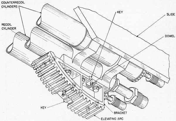
Fig. 8-Elevating Arc
details described in the following paragraphs. The system functions with the counterrecoil system to control the speed and travel of the gun-housing assembly in recoil, and to provide buffing action to bring the assembly to rest in counterrecoil.
5. Cylinder. The recoil cylinder is a steel tube 37.2 inches long, weighing 165 pounds. Its maximum outside diameter is 7.2 inches, but for part of its length it is machined to a diameter of 6.75 inches to form a tight fit in the cylinder supports. A thrust collar screwed on the rear of the cylinder, and a shoulder on the forward cylinder-support, prevent fore-and-aft movement of the cylinder relative to the slide. A lockscrew in the slide engages a hole in the cylinder to prevent rotation. The bore of the cylinder has a diameter of 5.6 inches for the greater part of its length to receive the cylinder liner. A reduction of diameter to 4.79 inches near the rear of the cylinder provides a shoulder against which the liner is seated. The rear of the cylinder is threaded on the outside to receive the thrust
collar, and on the inside to receive the packing nut. The front end of the cylinder is threaded on the inside to receive the cylinder head. Three equally spaced tapped holes are located just to the rear of the cylinder head for the filling, vent, and drain plugs.
6. Cylinder liner. The liner is a 23-pound, centrifugally cast-bronze tube having an overall length of 28.35 inches and an inside diameter of 5.25 inches. Three equispaced longitudinal grooves of varying depth are cut for a distance of 21.6 inches in the center portion of the liner. These grooves function to control the flow of liquid in the cylinder from one side of the piston to the other during its 20-inch recoil and corresponding counterrecoil movement. The throttling action thus obtained, operating in conjunction with the counterrecoil spring, serves to give controlled brake action during recoil and counterrecoil.
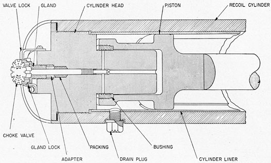
7. Cylinder head. The nickel-copper-aluminum alloy cylinder head is a combination head, buffer
28
PLATE 13
29
plunger, and seat for the choke valve (fig. 9). It is threaded into the front end of the recoil cylinder and takes up against a copper gasket. The plunger acts to displace hydraulic fluid in a cylindrical bore in the piston during the last few inches of piston travel during counterrecoil. The liquid thus displaced is forced through a restricted passage in the cylinder head, and is positively controlled by the setting of the choke valve. The adjustment of this valve, described in paragraph 27, is intended to provide return-to-battery choke action in 1.5 seconds from the full recoil position with the gun at 0° elevation.
8. Piston rod. The piston and piston rod, weighing 82 pounds, are forged integrally, with an overall length of 47.2 inches. The piston head has a cylindrical bore (into which a grooved bronze bushing is screwed) which rides over the 3-inch plunger of the cylinder head in the last few inches of counter-recoil movement. The outer end of the piston rod is threaded to receive the thrust collar. A locking sleeve, just forward of the thrust collar, forces the collar against a shoulder in the gun-housing and locks the piston rod in place.
Counterrecoil System
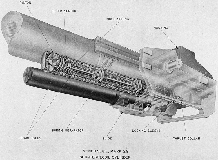
9. The counterrecoil system acts to return the gun to battery at the end of the recoil movement. It also functions with the recoil system to absorb the energy of recoil. It comprises two cylinders with assembled counterrecoil springs, pistons, and counterrecoil rods (pl. 14). The cylinders are mounted adjacent to and on either side of the recoil cylinder.
10. Counterrecoil cylinder. Each cylinder is a forging of nickel-copper-aluminum alloy machined to an outside diameter of 6.7 inches and an inside diameter of 6 inches. The tube is 66.35 inches in length and weighs 107 pounds. Both ends are threaded on the inside to receive a nut in the forward end and a locknut in the after end. A shoulder machined on the after section bears against a recess in the forward slide support for the cylinder. A lockscrew prevents the cylinder from turning in the support. A 6-inch sleeve, which slides over the rear end of the cylinder, is held against a similar recess in the after cylinder support by the locknut which screws into the cylinder. This nut is prevented from turning by the lock plate illustrated in figure 10.
Fig. 9-Recoil Cylinder Choke Valve
30
PLATE 14
31
Fig. 10-Counterrecoil Cylinder Lock Plate
Drain and vent holes are drilled in the bottom and top of the cylinder to drain it after submergence, and to prevent the building up of air pressure or creation of a vacuum during recoil and counterrecoil movement of the piston.
11. Counterrecoil rod. A thrust collar threaded and pinned to the end of each 76.65-inch counter-recoil rod is held in a recess in the gun housing by a threaded locking sleeve. The rod has a diameter of 1.312 inches and weighs 30 pounds. The forward end of the rod has a slightly smaller diameter,
threaded to receive the disc-shaped piston which is pinned in place at assembly. The rim of the piston is scalloped to permit free flow of air from one side to the other during recoil and counterrecoil movement.
12. Counterrecoil springs. There are three pairs of coil springs arranged longitudinally in each cylinder. Two spring separators, which are free to move on the counterrecoil rod, serve to correlate the action of the three pairs into that of one long inner and one long outer spring. Each of the three
32
outer springs requires a force of approximately 200 pounds, and each inner spring a force of approximately 150 pounds for each inch of compression. The springs are assembled with a total compression of about 7500 pounds for each cylinder to hold the gun positively in the battery position. The 20-inch recoil movement of the gun further compresses the springs to produce a working force of approximately 15 tons in the two cylinders to return the gun to battery.
Breech Mechanism Elements
13. The left side plate of the slide is machined to provide an operating recess and pivot bearing (pl. 7) for the cam plate described in paragraph 16, chapter 2. The right side plate is machined to receive the hand-breech-operating mechanism bearings and the operating handle latch bracket (fig. 6). This mechanism is described in paragraph 17, chapter 2.
Housing Guides
14. The inside face of each side plate of the slide is machined its entire length to provide a slot into which a 54-pound bronze bearing strip is push-fitted and secured by screws. This strip is two inches high, and extends approximately one inch out from the plate to form a guide and support for the guide rails of the gun-and-housing assembly. Lubrication is supplied through grease gun fittings in the side plates of the slide. Drilled holes in the bearing strip, connecting with these fittings, convey the lubricant to the bearing surfaces where it is spread by the lubricant grooves in the guide rails (par. 10, ch. 2).
Elevating Arc
15. A large cast-steel weldment is keyed and bolted to the bottom of the slide, as shown in figure 8, to form a bracket for the elevating arc. The 57° arc is a 52-pound aluminum-bronze piece, 6 inches in width, with 19 teeth cut to mesh with the drive pinion of the elevating gear. It is keyed and secured to.. the bracket with cap screws. Adjustment of pitch-line contact of the arc and pinion is obtained by means of shims between the arc and bracket.
Counterbalance Weight
16. The counterbalance weight (pl. 12) is a 354-pound steel weldment mounted on top of the side plates of the slide. It acts to counterbalance the slide, housing, and gun as the assembly is elevated or depressed.
FOOT-FIRING MECHANISM
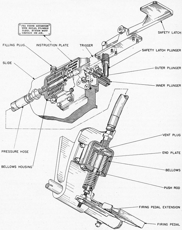
17. Arrangement of the mechanism. To fire the gun, it is necessary to actuate the sear push rod to disengage the sear from the firing pin cocking sleeve, as described in paragraphs 22 to 25, inclusive, chapter 2. In normal operation this is accomplished with the foot-firing mechanism illustrated in figure 11. (The figure shows the inner plunger in position ready to fire when the safety latch is operated by the loader.) The lower elements of the mechanism comprise a pivoted foot pedal and a spring-loaded bellows and plunger. They are attached to the pointer's foot pedal support bracket as shown on plate 3. The rest of the mechanism, consisting of a corresponding bellows arrangement, a trigger, a firing plunger, and a safety latch, is attached to the slide. The two bellows are connected by section of flexible pressure hose..
18. Firing mechanism operation. When the pointer depresses the right foot pedal, a lateral extension of the heel of the pedal forces the bellows push rod up one-quarter inch. When released, the foot pedal and the push rod are returned to position by the push rod spring. As the push rod forces the end plate in the bellows housing upward, hydraulic fluid is forced through the flexible hose into the bellows housing on the side plate of the slide. The bellows itself functions to prevent fluid leakage around the plunger and to ensure a positive flow of the fluid through the hose. (If the action of the mechanism is not positive, there is likelihood that a leak in the bellows exists, permitting fluid to escape through the opening in the housing to the atmosphere.) Flow of fluid into the bellows on the slide forces its end plate and push rod rearward the same distance and at the same speed as the movement of the firing pedal. This push rod acts against the forward lug of the trigger to turn it on its pivot and force its inside lug against the outer firing plunger. The outer plunger acts through the plunger spring to move the inner plunger; the spring being stiff enough to act as a rod in normal operation. The inner plunger engages the sear push rod which, in turn, pushes the sear out of the way of the firing pin cocking sleeve. The action obtained from the depression of the foot pedal to movement of the sear is quick and positive, and is designed to function in as short a time as possible between the pointer's "will to fire" and the ignition of the powder charge. A handle on the
33
Fig. 11-Foot-Firing Mechanism
34
trigger provides a means of firing the gun in case of failure of the hydraulic mechanism.
19. Firing mechanism safety latch. As the gun recoils, a camming surface on the housing forces the inner firing plunger outboard against its spring. A spring-loaded safety plunger extends vertically downward from the top of the side plate of the slide to engage a lug on the top of the inner plunger when the latter is forced back in recoil. This plunger prevents firing the gun until the loader moves clear of the path of recoil and depresses the latch lever. If the pointer has kept his firing pedal depressed, the gun will fire when the loader releases the safety latch. If he has not, the inner plunger will move in just far enough to contact the sear push rod, and the gun will fire when the pointer next depresses the foot pedal.
[ch3] The inner plunger is also forced back and the safety latch engaged by lowering and raising the breech block. This feature was added by Ordalt 2057.
MAINTENANCE AND OPERATING
INSTRUCTIONS
20. General instructions. The slide assembly, including the recoil and counterrecoil systems, is to be operated and maintained, adjusted and exercised, in accordance with the regulations of the Ordnance Manual, the instruction plates on the assembly, and the specific instructions of this chapter. The importance of proper care, complete regular servicing, and frequent, thorough inspection cannot be overemphasized. This applies particularly to the recoil and counterrecoil systems.
21. Maintenance precautions. The following are prescribed for general maintenance care of the slide assembly:
(a) The housing guides must be kept clean and free of corrosion, grit, and gummed lubricant.
(b) Do not deface, alter, or paint over, the legends of name and instruction plates.
(c) Special tools, spanner wrenches, open-end wrenches, etc., are provided for servicing, assembly, and disassembly of the recoil and counterrecoil systems. These tools and no others are to be used in such maintenance.
(d) The recoil system is to be filled with liquid designated by latest revision of Ordnance Data 1914. Always strain the fluid through a wire strainer of 100-mesh or finer.
(e) Maintain the recoil cylinder drain, vent, and filling plugs tight at all times.
(f) Maintain the recoil cylinder head buffer needle valve in adjustment as described in paragraphs 7 and 25.
(g) Air in the foot-firing mechanism will result in faulty operation. Vent air as described in paragraph 24.
[ch2] (h) "The counter-recoil springs should be removed every three months and the plating inspected. In the event the condition of the spring indicates that replating is necessary, the replating process shall be accomplished in strict accordance with O.S. 1083 and the date and overhauling activity recorded on the gun record card."
22. Lubrication. All parts of the assembly must be lubricated according to the frequency, and with the lubricants specified on the lubrication charts appended. See lubrication instructions and references, chapter 10.
23. Recoil cylinder-filling. When the recoil cylinder is correctly filled, it must have a void space to accommodate expansion of the fluid or the gun will not return to battery. When filling the cylinder in - accordance with the instruction plate (pl. 13), sufficient time must be allowed for the liquid to seep by the piston to fill the after portion of the cylinder. If the liquid is not given time to seek its level, it will flow out of the vent hole and indicate that the cylinder is filled to the proper level, when only the front portion is full.
24. Firing mechanism filling. The procedure for filling and venting the firing mechanism for correct performance is as described below. For adjustment see paragraph 26.
(a) Depress gun or manipulate hose so no air is trapped in system.
(c) Fill with recoil cylinder liquid, O.D. 1914; when lower housing is full replace vent plug.
(d) Continue to fill to overflowing, replace upper filling plug, pump foot pedal 20 to 30 times, remove upper filling plug.
(e) Repeat operation (d) two or three times. The last time pull upper bellows push rod out about 1/4 inch and secure while filling and pumping. Allow push rod to return to normal and expel excess liquid. Secure upper filling plug.
[ch3] Record the filling temperature for future reference.
ADJUSTMENTS
25. All elements of the slide are correctly positioned and require no adjustment if installed according to the general arrangement and detail drawings. Adjustments, as described below, are provided for the trigger mechanism and for the recoil cylinder choke valve in case of faulty operation.
[ch3] 26. Foot firing mechanism adjustment. The foot firing mechanism illustrated in figure 11 is adjusted as follows:
35
[ch3] 26. Foot firing mechanism adjustment. The foot firing mechanism illustrated in figure 11 is adjusted as follows:
(a) With foot tread released, the adjusting bolt 253447-4 on rear end of foot tread should contact the push rod, 256908-3, in its furthest extended position.
(b) Changes in temperature will produce expansion or contraction of the hydraulic fluid. If temperatures encountered, or expected to be encountered in the near future, are 40°F or more, above or below the temperature at which the system was last filled or adjusted, the resulting expansion or contraction should be compensated for as follows:
(1) For operation in temperatures considerably above that at which the system was last filled or adjusted. The system should be vented by removing the upper filling plug. This will allow the push-rod to return to the normal position and expel the excess liquid. In the normal position, the collar on the push-rod contacts the upper bellows housing. Any extension of the rod from this position indicates expansion of the liquid.
(2) For operation in temperatures considerably below that at which the system was last filled or adjusted. Liquid should be added to completely fill the system. Entrapped air in the system should be eliminated by following the procedure of paragraph 24(d) and (e).
The temperature at which the above liquid adjustment is made should be recorded for future reference.
(c) The push rod end on the upper bellows plunger is adjusted so that the outer plunger 254025-2 extends 1.125 inch from the slide.
(d) Check action of safety latch as follows: Cock firing pin by lowering and raising the breech block. Lowering or raising the block automatically engages the safety latch. (This feature was added by either 2057). It should now be impossible to fire with either trigger lever or foot tread.
(e) Press handle of safety latch to release. It should now be possible to fire with either trigger lever or foot tread.
(f) Remove firing pin and observe action of sear while performing the checks (c) and (d). With safety latch released, approximately 0.17 inch of sear shoulder should be in position to restrain firing pin.
[ch3 removed old a-f]
27. Recoil cylinder choke valve adjustment. The choke valve illustrated in figure 9 is adjusted to correctly throttle return to battery by measuring
* The firing mechanism is being redesigned so that the inner plunger of the safety latch mechanism will be latched whenever the breechblock rises. This will be accomplished by making the sear push rod longer. Existing assemblies will be modified to agree with the new design by Ordalt 2057. Thus, full protection will be provided for the loader. Figure A illustrates a temporary safety device being used by ships until production begins on the new design. This temporary device permits manual latching of the inner plunger at any time. Note also the instructions of chapter 2, paragraph 31(e).
FIGURE A
the time of return from full recoil. Set the valve when the action is timed at 1.5 seconds from pelican hook release with the gun at 0° elevation.
DISASSEMBLY AND ASSEMBLY
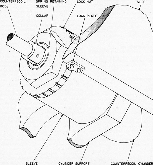
28. Disassembly and assembly of the slide is apparent from the general arrangement and detail drawings, except for the counterrecoil cylinders which are disassembled as follows:
(a) With the gun in battery, remove lock plate 253536-5.
(b) Back off locking sleeve 253538-5. This will permit the spring to expand until collar 253538-7 comes up against spring retaining sleeve 253538-3.
(c) Unscrew nut 253536-4 and lockscrew 253536-6.
(d) Move the counterrecoil cylinder assembly forward sufficiently to remove lock pin 253538-8 and thrust collar 253538-6 from the rod; slip off locking sleeve 253538-5.
(e) Withdraw the cylinder assembly from the slide and slip nut 253536-4 and sleeve 253536-2 off counterrecoil rod 253538-1.
(f) Replace nut 253536-4.
(g) With compressor washer 57627-41 between compressor body 57627-40 and nut 253536-4, turn compressor screw 57627-4 into counterrecoil rod 253538-1. See figure 31.
(h) Holding the compressor screw 57627-4, turn compressor nut 57627-13 clockwise until collar 253538-7 is accessible through the opening in the compressor body.
(i) Remove nut 253536-3 from the forward end of the counterrecoil cylinder.
(j) Remove collar 253538-7 by removing machine screws 12-Z-8-302.
(k) Holding compressor screw 57627-4, turn compressor nut 57627-13 counterclockwise until the counterrecoil springs are wholly decompressed.
(l) Holding the counterrecoil rod from turning, disassemble the spring compressor from the rod.
(m) The springs and rod may now be withdrawn from the cylinder.
To reassemble the unit, follow the above procedure in reverse order.
36
PLATE 15
37
Chapter 4 GUN MOUNT CARRIAGE 5-INCH CARRIAGE MARK 33
GENERAL DESCRIPTION
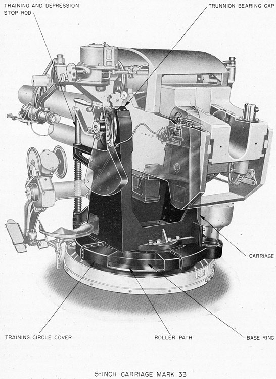
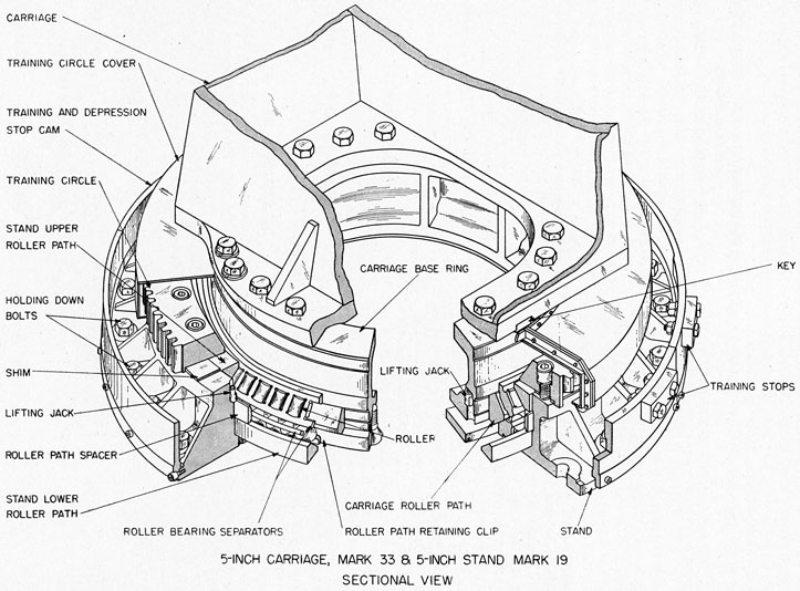
1. The Carriage Mark 33, is an assembly of a large base ring casting, a roller path, a gun carriage weldment, trunnion bearings, a training and depression stop device, and elements of the foot firing mechanism. It provides a trunnion mount for the slide so that the gun may be elevated and depressed; and is itself mounted on roller bearings in the stand so that the gun may be rotated through the desired arc of train. Plate 15,* illustrates the carriage assembly with the other parts of the mount shown in phantom. Roller path details are shown on plate 17, chapter 5, in connection with the stand.
2. Components. The 2100-pound carriage comprises the following designated parts and assemblies. They are described in this chapter in the sequence listed:
Carriage weldment
Base ring
Roller path
Trunnion bearings
Training circle cover
Training and depression stop
Firing mechanism elements
3. Carriage weldment. The gun carriage proper is a 940-pound weldment of five plates-bottom, front, rear, and two sides-forming a rigid structure which is mounted on the base ring. Trunnion blocks are welded to the top of the side plates and are machined to receive the trunnion roller bearings and bearings caps. Three pads, on the front plate near the left side, support the upper and lower brackets for the training and depression stop. Two pads on this same plate are provided to carry the pinion bracket for the elevating gear (see ch. 7). A pad, welded to the right, rear, and bottom plates, supports the pinion bracket for the training gear (see ch. 6). Bolt holes and a transverse keyway are provided in the bottom plate for attachment to the base ring.
* The training circle cover and corresponding parts of the stand have been cut away to show the carriage roller path.
4. Base ring. The base ring is a double-annealed steel casting, having an outside diameter of 34.25 inches and weighing 523 pounds. It is machined to receive the carriage roller path. Drilled and tapped holes are provided for attachment of the carriage weldment and the roller path retaining clips. A transverse keyway and an aluminum-bronze key serve to align the carriage with the base ring. All machined surfaces, including the drilled and tapped holes, are zinc plated and chromate dipped. The ring serves to carry the load of the carriage assembly and transmit it to the stand (described in ch. 5) through the carriage roller path and roller bearings.
5. Roller path. The carriage roller path is a 203-pound forged ring of nickel-copper-aluminum alloy, with the roller bearing surfaces ground and polished. The ring is a shrink fit onto the lower part of the base ring, which is equipped with lifting jacks for removing the ring (pl. 17). Four heavy clip's made from steel plate are secured to the bottom of the base ring and serve as retainers for the roller path. Each of the two polished bearing surfaces is cut at an angle of 45° with the horizontal to conform to the upper and lower roller paths of the stand. Thus the load of the carriage, slide, and gun is transmitted to the stand through the roller bearings.
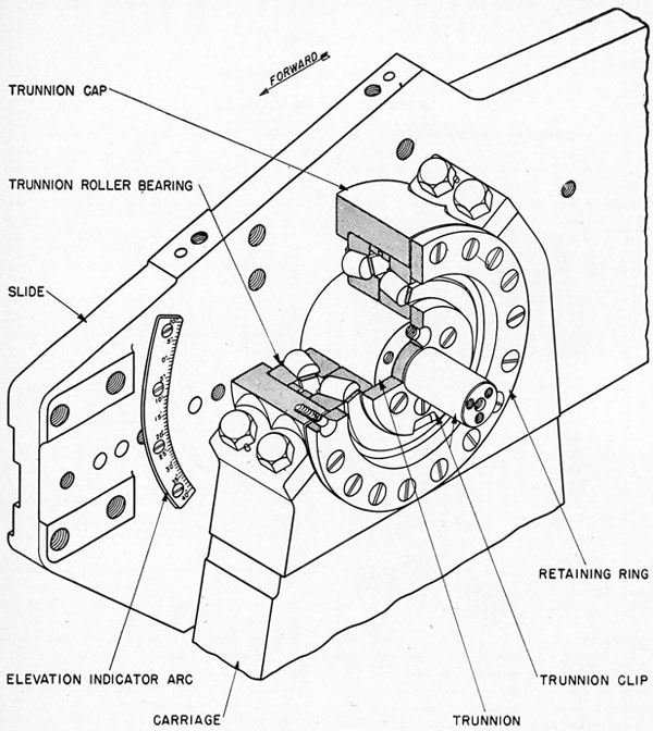
6. Trunnion bearings. Double, tapered roller bearings, mounted in the gun carriage cheeks in the arrangement illustrated in figure 12, provide frictionless bearings for the slide trunnion journals. These special bearing assemblies are of commercial design and manufacture, and transmit radial and axial thrust of the slide assembly to the carriage. The latter transmits these thrusts through the roller paths, and thence to the ship's structure. The bearings are held in place by the trunnion caps and trunnion clips, which also serve to exclude weather and retain the lubricant. Lubrication is furnished through grease fittings and the grease slots in the roller spacer.
7. Training circle cover. The training circle cover
38
Fig. 12-Trunnion Bearing
is designed to protect the training circle from damage incidental to operating the mount or to handling equipment around the mount. It is neither pressureproof nor watertight and does not completely enclose the training circle on the bottom.
It is made up in four welded sections bolted together and secured with machine screws to the base ring of the carriage. One of the sections has a radial extension open at top and bottom for passage of the training circle pinion and its shaft.
39
Plate 15 and plate 16 illustrate its assembly to the carriage.
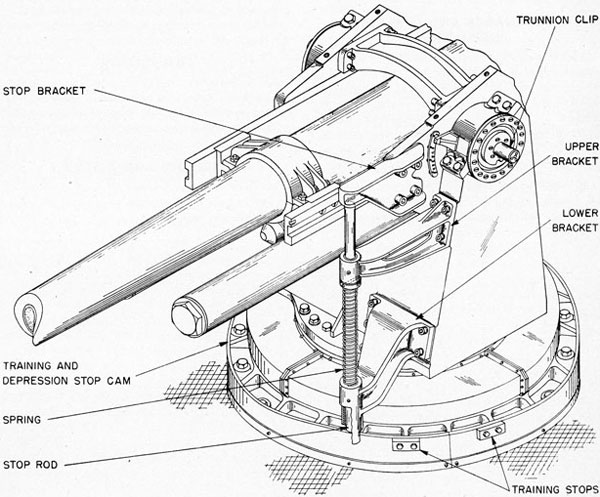
8. Training and depression stop (fig. 13). This assembly functions to stop the train of the mount and the depression of the gun to prevent firing into the ship's structure. A vertical stop rod is mounted to slide in two brackets which are attached to the front of the carriage. A machined surface is provided on each side of the lower bracket to contact one of the training stops attached to the training and depression stop cam (described in ch. 5), and thus limit movement in train. The depression stop bracket on the slide makes contact with the top of the vertical rod and forces it down against the cam on the stand (see par. 7, ch. 5), thus limiting
the depression. The cam surface is cut at assembly so that, as the gun is swung clear of the ship's structure, the possible depression is increased up to a maximum of 10 degrees. A compression spring holds the stop rod up in its brackets so that the top of the rod is in contact with the stop bracket on the slide when the gun is at 0° elevation. This spring also gives some buffing action. when the rod is forced down against the cam. Figure 13 shows the gun trained near the left training stop, with the stop rod over the highest part of the cam.
9. Firing mechanism elements. The pointer's foot pedal bracket is bolted to the elevating gear worm-wheel bracket (ch. 7) and forms a mounting for the bellows housing of the foot firing mechanism
Fig. 13-Training and Depression Stop
40
(described in ch. 3), as well as the foot pedals. Hydraulic tubing of the foot firing mechanism is attached to the brackets and the left side plate of the carriage, as illustrated on plate 3.
10. The pointer's and trainer's seat brackets are secured to the left and right carriage cheeks, respectively. A triangular pointer, secured to the left trunnion bearing cap, aligns with markings on the elevation indicator arc on the slide to indicate the angle of elevation of the gun.
MAINTENANCE AND OPERATING INSTRUCTIONS
11. General. The carriage assembly is to be operated and maintained, lubricated, and exercised in accordance with the instructions of the Ordnance Manual and of chapter 10 of this pamphlet. Maintenance of the carriage assembly consists principally of regular inspection and servicing to ensure that all components and attached devices are secure, free from corrosion, and properly lubricated.
12. Lubrication. The lubrication charts appended specify the points of lubrication, the required lubricant, and frequency of application for each
point or mechanism of the carriage assembly. Lubrication of the roller path bearings and the trunnion bearings is essential for preservation of those units; preservation has been anticipated, insofar as practicable, through extensive use of noncorrosive alloys and chromium or cadmium plating of the finished surfaces. Pitting and wear of plated surfaces can and will occur, however, if lubricating film is not maintained. It is, therefore, imperative that these bearings be inspected frequently as to adequacy of lubrication. Cold weather dilution or substitution, if employed, must be according to the directions and restrictions prescribed in chapter 10.
ADJUSTMENTS
13. A correctly installed carriage assembly, mounted on a stand that has uniform flange bearing on the foundation, should require no subsequent adjustment. Trunnion bearings are nonadjustable and should not be shimmed.
DISASSEMBLY AND ASSEMBLY
14. Disassembly and assembly of all elements of the carriage are apparent from the general assembly and detail drawings.
41
Chapter 5 GUN MOUNT STAND 5-INCH STAND MARK 19
GENERAL DESCRIPTION
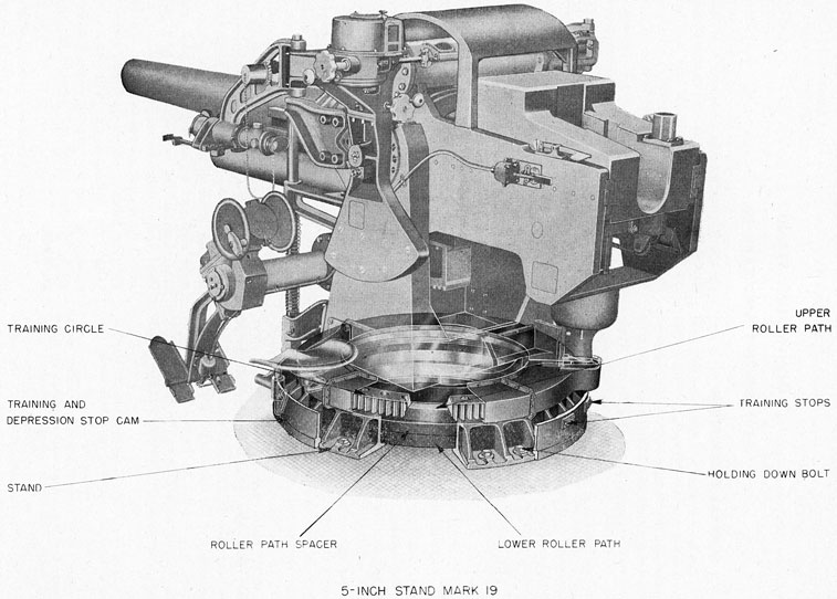
1. The gun mount stand is a large, circular, steel casting providing the deck flange and seats for the roller paths and the training circle. Plate 16 illustrates the arrangement of the major components of the stand relative to the mount as a whole.* Plate 17 illustrates the details of the stand and the mounting of the carriage in it.
2. Components. The stand assembly comprises parts and assemblies described in this chapter in the following sequence: **
Stand casting
Roller bearing assembly
Lifting jack
Training circle
Training and depression stop cam.
3. Stand casting. The 736-pound, double-annealed steel casting, which forms the support for the carriage, slide, housing, and gun, is secured to the ship's structure with 24 1-1/2-inch holding-down bolts which are embedded in a wood foundation. Lockscrews are located at assembly to prevent the holding-down bolts from turning. A flat surface is machined on the top of the stand to provide a mounting for the training circle. The inside diameter is 40.50 inches, machined to receive the upper and lower roller paths, Four holes are counterbored into the top of the stand to receive the lifting jacks for disassembly of the upper roller path; and four drilled and tapped holes are located in the base of the stand to receive jackscrews for disassembly of the lower roller path. The periphery of the base of
* The training circle cover is included with the stand in this plate to show its relation to the training circle. It is actually a component of the carriage.
** An azimuth scale, located around the stand, and a pointer secured to the carriage near the trainer, are to be added by Ordalt. The Ordalt will also provide a small shielded red light, a wet type storage battery, and a switch for illuminating the scale and pointer. The switch will also control the circuit to the elevation scale lamp - see footnote to ch. 3, par. 3.
the stand is machined to a diameter of 54.75 inches with drilled and tapped holes to provide a mounting for the training and depression stop cam. A cast, or stamped, arrow is aligned with a corresponding arrow on the foundation when the stand is mounted in the ship; the arrows point in the direction of the gun muzzle when the gun is in the stowed position.
4. Roller bearing assembly. This assembly consists of an upper and a lower roller path, rollers, two roller bearing separators, and a spacer ring. The two roller paths are identical rings of nickel-copper-aluminum alloy, either hot-rolled or forged, and heat treated. Each has an outside diameter of 40.502 inches and an inside diameter of 36.50 inches, and weighs 115 pounds. Their inside faces are finished, with fine-grinding and polishing, at an angle of 45° with the horizontal so that, when mounted in the stand, they present opposing surfaces to the carriage roller path (pl. 17) . They are shrunk into place in the stand, and are properly spaced with reference to each other by a 31.5-pound cast-bronze spacer ring. The rollers are made of the same material as the roller paths, and are cold-drawn and heat treated. Each is two inches long, weighs 1.1 pounds, and is finished by fine-grinding to a diameter of 1.5 inches. Each of two 36-pound cast-bronze separators holds 56 rollers equally spaced in pockets, with sufficient clearance to prevent friction between the rollers and the separator. One separator is assembled between the stand upper roller path and the carriage roller path, and the other between the carriage roller path and the stand lower path. Sixteen pads equally spaced around the separator serve to position and support the ring between the carriage and stand roller paths. The separators turn with respect to the roller paths, but they are light enough so that the sliding friction introduced through the pads is negligible.
5. Lifting jack. The lifting jacks illustrated on plate 17 are cylindrical bronze pieces placed 90° apart in counterbores in the inside circumference
42
Plate 16
43
Plate 17
44
of the stand casting. Lugs on the jacks project under the lower surface of the stand upper roller path. A tapped hole in each jack receives a one-half inch jackscrew at disassembly. When the screw has been turned into the jack until it bears against the stand, further turning forces the lifting jack up, and with it the roller path.
6. Training circle. The circular rack, with which the training gear pinion meshes to turn the carriage on the stand, is called the training circle. It is a 495-pound bronze casting with an outside diameter of 48.3 inches. It has 120 teeth cut on its outer face with a diametral pitch of 2.5. The circle is doweled and bolted to the stand, and has a stamped arrow on the top face which is aligned with a similar arrow on the stand at assembly. Four quadrant-shaped shims between the circle and the stand are machined at assembly to make the circle a tight fit against the top surface of the stand upper roller path, and thus the training circle acts as a retainer for the roller path.
7. Training and depression stop cam. Two 125-pound, semicylindrical cam blanks are mounted on the edge of the bottom flange of the stand and secured with cap screws. The two bronze blanks fit together to form a continuous, horizontal, flat ring three-fourths of an inch in width. The depression stop rod (described in ch. 4) strikes the upper surface of this ring when the gun is depressed to the allowable limit (fig. 13). The blanks are cut when the mount is first installed, so that their contour will ensure that firing will clear the ship's structure as determined by bore sighting. A thicker segment of the blanks is provided for the mounting of the training stops, which consist of brass lugs secured by through bolts. The centerline between the stops is off the fore-and-aft centerline of the ship by an amount equal to the horizontal distance between
the training and depression stop rod and the longitudinal centerline of the gun. An arrow stamped on the top of one blank indicates the proper position at assembly; the arrow points toward the muzzle when the gun is in the stowed position.
MAINTENANCE AND OPERATING
INSTRUCTIONS
8. General. Maintenance of the stand assembly consists mainly of the preservation of its component parts. Preservation has been anticipated, insofar as practicable, through extensive use of noncorrosive alloys, and chrome or cadmium plate of the finished surfaces. Pitting and wear of plated surfaces can and will occur, however, if a lubricating film is not maintained. It is imperative that the stand be inspected and lubricated according to the frequency and with the lubricants specified on the lubrication charts appended. Inspect more often if kerosene dilution of lubricants has been necessary. (See instructions of ch. 10.)
9. Holding-down bolts. Tap each holding-down bolt for indication of looseness or fracture as soon as practicable after engagement or operation in a heavy sea.
ADJUSTMENTS
10. The stand assembly has no adjustable elements. Shimming is not to be used to compensate for wear or deformation. Worn or deformed parts must be replaced with parts having the proper dimensions.
DISASSEMBLY AND ASSEMBLY
11. Disassembly and reassembly of the stand are apparent from the general arrangement and detail drawings. Lifting of the carriage from the stand is an operation for base or repair ship supervision, with appropriate equipment.
45
Chapter 6 TRAINING GEAR 5-INCH TRAINING GEAR MARK 16
GENERAL DESCRIPTION
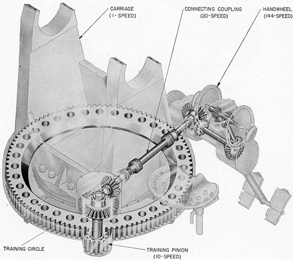
1. The Training Gear Mark 16 is a pinion drive machine operated by handwheels to rotate the carriage relative to the stand. Plate 18 illustrates the
gear in relation to the mount, with the brackets and casing phantomed to show the shafting and gears. Figure 14 shows the action and gear ratios of the mechanism.
Fig. 14-Training-Gear Arrangement
46
PLATE 18
47
2. Components. The training gear consists of the following assemblies, which are described in this chapter in the sequence listed:
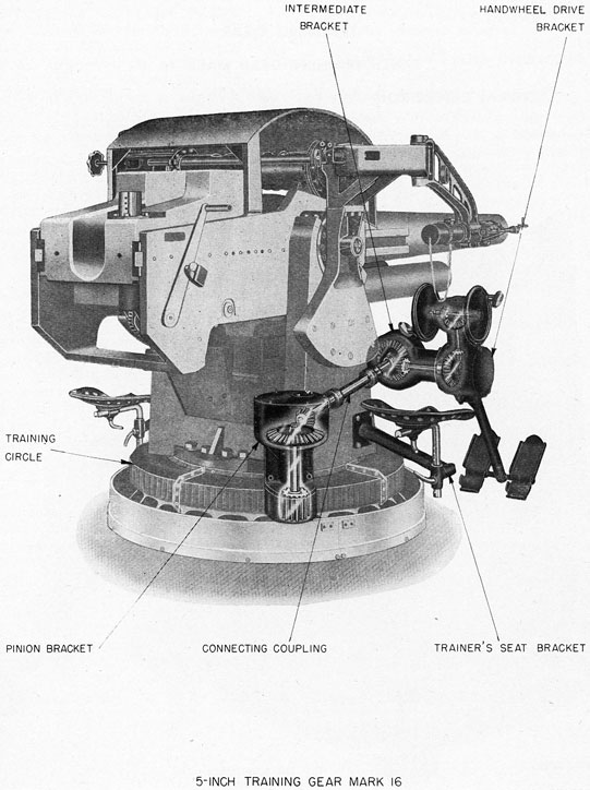
3. Handwheel drive assembly. The handwheel bracket (fig. 15) is a 24-pound bronze casting. Cast bronze bushings in two opposed cylindrical holes in the top of the casting support the handwheel shaft. This bronze shaft is splined at both ends to receive the 11.5-pound handwheels, which are cast-bronze discs 10 inches in diameter. The splines prevent the wheels from turning on the shaft, and retaining screws in the ends of the shaft secure the wheels in place. A handle is secured to the outer rim of each handwheel by a bolt on which the handle is free to turn. A 15-tooth bevel pinion is secured by a taper pin on a splined section of the handwheel shaft just inside the left bushing. This pinion meshes with a bronze bevel gear, which is held in place on a vertical bronze shaft by means of a locknut and lock washer. The gear has 27 teeth, so that one turn of the handwheels produces five-ninths of a turn (200°) of the vertical shaft. The shaft is held in two sleeve bushings in the bracket by the bevel gear and spacer on its top splined portion, and a collar near the lower end. This end is splined and carries a 15-tooth bevel pinion, meshing with a 30-tooth bevel gear pinned to the horizontal shaft of the intermediate bracket. The gear ratio from the handwheels to this shaft is 5 to 18, so that one turn of the handwheels results in 100° turn of the shaft. Clockwise rotation of the hand-wheels, as viewed from the right, produces right train. The bracket casting has a machined face on the front surface near the bottom for attachment of the trainer's footrest assembly.
4. Intermediate bracket assembly (fig. 16). The housing for that portion of the training gear between the handwheel bracket assembly and the connecting coupling is called the intermediate bracket. It is a 56-pound bronze casting, bolted on the right to the handwheel bracket flange and on the left to the elevating gear pinion bracket (described in ch. 7). The horizontal shaft extending from the handwheel bracket is supported in bushings in the
intermediate bracket, and carries a 16-tooth bevel pinion on its splined inboard end. The 14-pound bracket cover carries two bushings, which form the support for a flanged shaft extending downward and rearward to the connecting coupling assembly. A 32-tooth bevel gear, splined to the shaft and secured by a locknut, is driven by the pinion on the horizontal shaft. The gear ratio from the handwheels to the shaft out of the intermediate bracket is 5 to 36. That shaft therefore turns 50° for every full turn of the handwheels.
5. Connecting coupling assembly (fig. 17). This assembly consists of a hollow shaft (called the connecting coupling), two end couplings, and two coupling discs. The connecting coupling is a hollow cylindrical casting of aluminum bronze, having a flange on each end. On the face of each flange are two lugs, 180° apart, to engage with slots in the coupling disc. Each end coupling is an aluminum-bronze casting, having a flange with two lugs similar to those on the connecting coupling and a splined bore. The upper end coupling is secured by a taper pin to the end of the splined shaft extending from the intermediate bracket. The lower end coupling is mounted on the splined shaft extending from the pinion bracket. Each of the coupling discs has four slots, 90° apart, and fits between a flange on the connecting coupling and that on one of the end couplings; the lugs on the flanges engaging with the slots in the disc. This arrangement forms a direct connection between the intermediate bracket and the pinion bracket, and permits independent disassembly of one portion of the training gear.
6. Pinion bracket assembly (fig. 17). The pinion bracket is a 100-pound steel casting secured to the carriage weldment by 3/4-inch cap screws. The splined shaft which connects with the lower end of the connecting coupling is held by an integral thrust collar riding against a bronze bushing in the bracket. A second bushing inside the bracket forms the other bearing for the shaft. A 15-tooth bevel pinion is splined on the inner end of the shaft and secured by a locknut. This pinion meshes with a 30-tooth bevel gear which is splined, and secured by a locknut, to the upper end of a vertical shaft mounted in two bushings in the bracket. The main pinion, which meshes with the training circle on the stand, is an integral part of the lower end of this shaft. Thus, the gear ratio from the handwheels to the main pinion is 5 to 72, giving a rotation of 25°
48
of the main pinion for one turn of the handwheels. This pinion has 12 teeth, and the training circle 120 teeth, which results in 2.5° of carriage movement in train for each complete turn of the handwheels.
7. Trainer's seat bracket assembly. The trainer's seat is supported by the carriage, as shown on plate 18. The lever screws permit adjustment of the seat horizontally and vertically.
8. Footrest assembly. Two fixed foot pedals are mounted on braces welded to a support bracket which is bolted to the trainer's handwheel bracket, as shown on plate 18.
MAINTENANCE AND OPERATING INSTRUCTIONS
9. The training gear is to be maintained, operated, lubricated, and exercised in accordance with the regulations of the Ordnance Manual and the lubrication instructions of chapter 10 of this pamphlet.
ADJUSTMENTS
10. Elements of the training gear as initially erected are fitted in fixed adjustment. However, each set of gears is provided with laminated shims
Fig. 15-Handwheel Drive Assembly
49
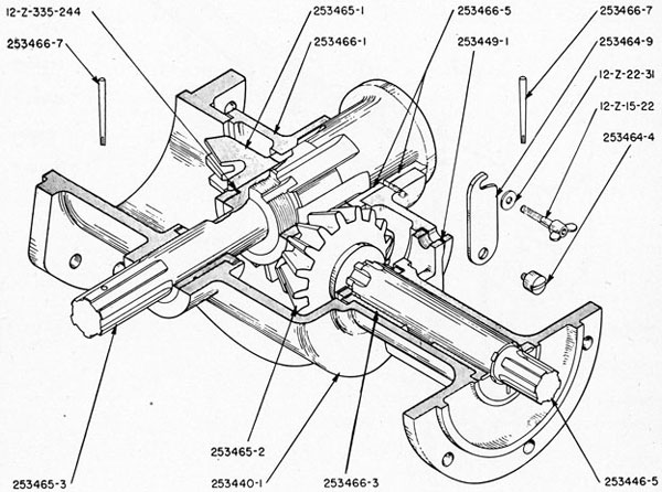
(253449-1 to 253449-6, inclusive) which may be modified as necessary to provide proper meshing of gears, if wear or shock of firing has affected the fitted adjustment. Change of shims must not be attempted to correct for misalignment due to sprung gears or shafting. Defective parts should be replaced.
DISASSEMBLY AND ASSEMBLY
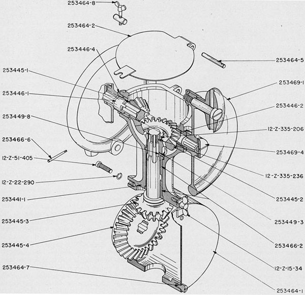
11. Disassembly of the handwheel drive assembly is accomplished as follows (fig. 15):
(a) Slack off on thumbscrew 253464-8 to unlock handwheel bracket cover plate 253464-2; swing the cover plate open.
(b) Pinch the slotted ends of the taper pin 253466-6 together, and pull the pin free of pinion 253445-1 and shaft 253446-1.
(c) Unscrew handwheel retaining screws 253469-4 and pull handwheels 253469-1 off splined shaft 253446-1.
(d) Tap the outboard end of shaft 253446-1 lightly with a leather maul to drive it out through the inboard bushing 253446-4. (Pinion 253445-1 should be supported as the shaft clears it.)
(e) Remove pinion 253445-1 from the bracket.
(f) If it is necessary to remove bushings 253446-2 and 253446-4, they should be cooled with dry ice until they can be forced out of the bracket, as they have diameters 0.0004-inch greater than the bores in which they fit.
(g) Remove handwheel bracket 253441-1 from intermediate bracket 253440-1 by unscrewing cap bolts 12-Z-51-405. Be careful to pull the handwheel bracket out horizontally to disengage pinion 253445-3 from gear 253445-4.
(h) Loosen pivot screw 253464-7, unclamp thumb screw 12-Z-15-34, swing side cover 253464-1 down clear of the bracket opening, and tighten the pivot screw.
Fig. 16-Intermediate Bracket Assembly
50
it Remove locknut 12-Z-335-206 and lock washer 12-Z-335-236 from the vertical shaft.
(j) Remove gear 253445-2, spacer 253449-8, and shim 253449-3 from the top of the shaft.
(k) Remove pinion 253445-3 and shim 253449-3 from the bottom of the shaft, and withdraw the shaft through the bottom of bracket 253441-1.
(l) Bushings 253466-2 are 0.0004-inch greater in diameter than the bore in which they fit. As no jackscrew holes are provided for disassembly, it is necessary to cool the bushings with dry ice until they can be driven out with a maul and fibre cylinder.
12. Disassembly of the intermediate bracket assembly figure 16, and the connecting coupling assembly, figure 17, is as follows:
(a) Withdraw taper pin 253466-7 from gear 253445-4 in the handwheel drive assembly, and slip the gear off shaft 253446-5.
(b) Withdraw taper pin 253466-7 from end coupling 253461-3.
(c) Move end coupling 253461-3 forward on shaft 253465-3; remove coupling discs 253461-4 and connecting coupling 253461-1.
(d) Remove intermediate bracket 253440-1 from the elevating gear pinion bracket by taking out cap screws 12-Z-51-408.
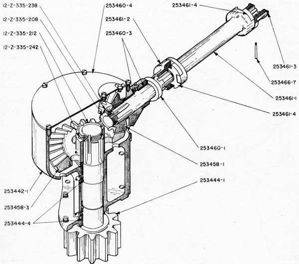
Fig. 17-Pinion Bracket and Connecting Coupling
51
(e) Unscrew locknut 12-Z-335-244 clear of threads on shaft 253465-3.
(f) Unscrew cap screws and pull cover 253446-1 and shaft 253465-3 clear of bracket 253440-1 and gear 253465-1.
(g) Bushings 253466-5 are 0.0009-inch oversize in the bore in bracket 253440-1 and must be cooled with dry ice to permit withdrawal.
13. Disassembly of the pinion bracket assembly (fig. 17) is performed as follows:
(a) Remove end coupling 253461-2 from shaft 253460-1.
(b) Remove cover plate 253460-4 from pinion bracket 253442-1.
(c) Remove locknut 12-Z-335-208 and lock washer 12-Z-335-238 from shaft 253460-1.
(d) Withdraw shaft 253460-1 from the pinion bracket and pinion 253458-1.
(e) Remove all cap screws from and lift pinion bracket 253442-1 vertically to clear pinion 253444-1 from the training circle.
(f) Remove locknut 12-Z-335-212, lock washer 12-Z-335-242, and gear 253458-3 from the pinion shaft, and withdraw pinion 253444-1 from the pinion bracket.
(g) Bushings 253444-4 are 0.0008-inch and bushings 253460-3 are 0.0006-inch oversize in the corresponding bores in the pinion bracket. They must he cooled with dry ice to permit withdrawal.
14. Reassembly of the training gear is performed by reversing the order of the steps given for disassembly.
52
PLATE 19
53
Chapter 7 ELEVATING GEAR 5-INCH ELEVATING GEAR MARK 16
GENERAL DESCRIPTION
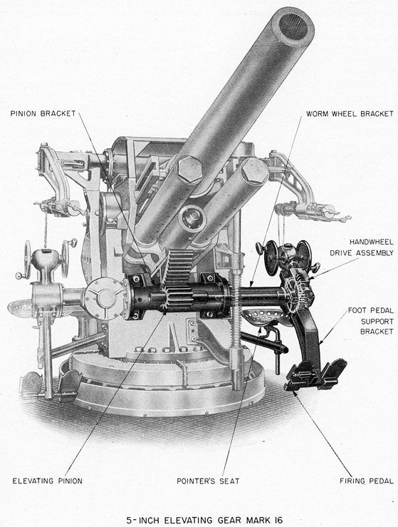
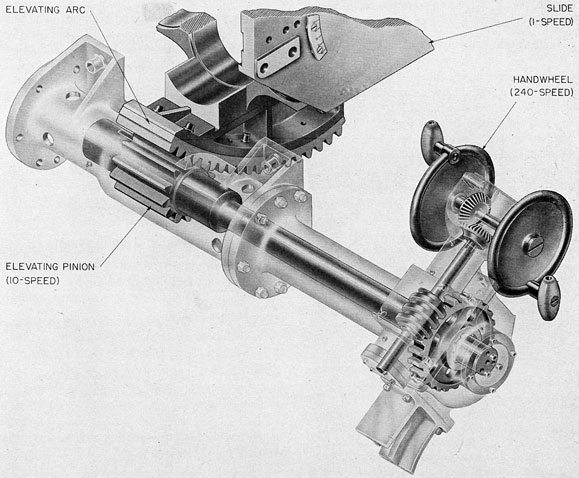
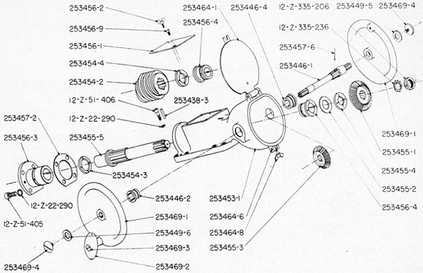
1. The Elevating Gear Mark 16 is a pinion drive machine operated by a handwheel mechanism to rotate the slide, and with it the gun, about the trunnion axis. Plate 19 illustrates the gear in relation to the mount, with the brackets and casings phantomed to show the shafting and gears. Figure 18 shows the action and gear ratios of the mechanism.
2. Components. The elevating gear consists of
the following assemblies, which are described in this chapter in the sequence listed:
3. Handwheel drive assembly. The handwheel bracket is a 34-pound steel casting bolted to the wormwheel bracket described in paragraph 4. Two
Fig. 18-Elevating Gear Arrangement
54
handwheels and a handwheel shaft are similar to, and are mounted on the handwheel bracket in the same manner as those of the training gear described in chapter 6. (Fig. 19 shows the parts of the handwheel drive assembly disassembled.) A 28-tooth bevel pinion on the shaft meshes with a 28-tooth bevel gear which is splined to the end of a worm shaft and secured by a locknut. The worm shaft extends forward and downward, and is supported in three bearing bushings in the bracket. The forward one of these bearings is held in the end of the bracket by cap screws. A single thread right-hand worm is splined on the worm shaft and rests against a collar which is integral with the shaft. End thrust is taken by three thrust washers, one in front of the bevel gear, one behind the worm, and one in front of the shaft collar; all bearing against the bearing bushings. Clockwise rotation of the handwheels, as viewed from the right, causes gun depression.
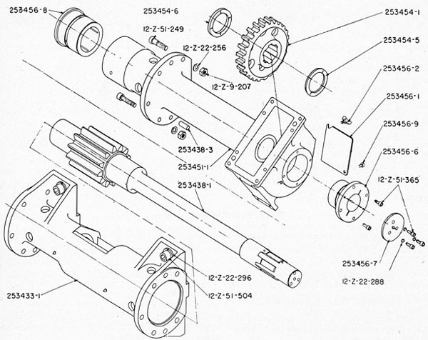
4. Pinion bracket assembly. The pinion bracket is a 105-pound steel casting extending across, and bolted to, the carriage. Plate 19 illustrates the general arrangement of this assembly, and figure 20 shows the parts disassembled. A flange on the right end of the pinion bracket supports the training gear assembly. The wormwheel bracket is an 88-pound steel casting, part of which extends into the bore of the pinion bracket. It is secured to a flange on the left end of the latter. The pinion is integral with its shaft, and a spline near the left end of the shaft carries the wormwheel. The shaft is mounted in four bearing bushings-one in the pinion bracket and three in the wormwheel bracket. The 24-tooth wormwheel is driven by the worm of the handwheel drive, and thus turns through 15° for one revolution of the handwheels. The 12-tooth pinion meshes with the elevating arc to give a gun elevation of 1.5° for one complete turn of the hand-wheels.
5. Pointer's seat bracket assembly. The pointer's seat is mounted on a pipe weldment assembly bolted to the carriage, as illustrated on plate 19. The lever screws permit adjustment of the seat horizontally and vertically.
6. Foot pedal support bracket assembly. The 34- pound steel foot pedal support bracket is bolted to the lower front flanged surface of the wormwheel bracket, as illustrated on plate 19. A cross shaft
at the bottom of the bracket supports the fixed left pedal and forms a pivot for the right, or firing, pedal. The firing mechanism bellows housing is mounted on the back of the bracket, so that the foot lever attached to the right foot pedal will operate the bellows plunger as the pedal is depressed by the pointer. A sleeve welded to the underside of the pedal carries -a spring-loaded plunger. This plunger enters a hole in a small bracket attached to the pedal support bracket, and thus prevents accidental depression of the pedal. A foot lever attached to the plunger extends up through a slot in the pedal. By shifting his foot to the right, the pointer can withdraw the plunger so that the pedal can be depressed to fire the gun.
MAINTENANCE AND OPERATING INSTRUCTIONS
7. The elevating gear is to be maintained, operated, lubricated, and exercised in accordance with the regulations of the Ordnance Manual and the instructions of chapter 10 of this pamphlet.
ADJUSTMENTS
8. The elevating gear is installed with fixed adjustments. It may be necessary to adjust the meshing of gears by the use of shims where wear or shock of firing has caused improper meshing, but such adjustment must not be used to correct for misalignment due to warping or springing of shafting or gears.
DISASSEMBLY AND ASSEMBLY
9. Disassembly of the handwheel drive assembly (fig. 19) is accomplished as follows:
(a) Slack off thumb screw 253464-8 and swing cover 253464-1 open.
(b) Remove taper pin 253457-6 from pinion 253455-3 and shaft 253446-1.
(c) Remove handwheel retaining screws 253469-4 and slip handwheels 253469-1 off the splined ends of shaft 253446-1.
(d) Tap the outboard end of shaft 253446-1 lightly with a leather maul and withdraw the shaft inboard free of the bracket 253453-1 and pinion 253455-3.
(e) Remove pinion 253455-3 through the rear opening of the handwheel bracket.
55
Fig. 19-Handwheel Drive Assembly
(f) Remove bushing 253456-3, using jackscrews-in the two 3/8-inch tapped holes in the bushing flange.
(g) Remove locknut 12-Z-335-206, lock washer 12-Z-335-236, gear 253455-1, shim 253455-4, and thrust washer 253455-2 from shaft 253455-5.
(h) Open cover plate 253456-1.
(i) Force shaft 253455-5 forward out of bracket 253453-1 and worm 253454-2.
(j) Remove worm 253454-2 and thrust washer 253454-4 through the opening exposed by removing cover plate 253456-1.
(k) Bushings 253446-2 and 253446-4 are 0.0005- inch and bushings 253456-4 are 0.0004-inch oversize in their respective bores, and must be cooled with dry ice for removal.
10. Disassembly of the pinion bracket assembly (fig. 20) is performed as follows:
(a) Remove the handwheel bracket from the wormwheel bracket. Also remove the firing
mechanism bellows housing from the pedal support bracket.
(b) Remove cap screws 12-Z-51-249 holding wormwheel bracket 253451-1 to pinion bracket 253433-1.
(c) Withdraw wormwheel bracket 253451-1, its assembly, and the pinion shaft 253438-1 as a unit outboard and clear of the mount.
(d) Bushing 253438-2 may be withdrawn by cooling with dry ice-it is a force fit into bracket 253433-1.
(e) Remove cap screws 12-Z-51-365, retainer 253456-7, and end bearing 253456-6 from the worm-wheel bracket.
(f) Withdraw pinion shaft 253438-1 (toward the pinion end of the shaft) from the wormwheel bracket and wormwheel 253454-1.
(g) Remove wormwheel 253454-1 and thrust washers 253454-5 and 253454-6 from the worm-wheel bracket through the opening where the worm-
56
wheel engages the worm of the handwheel drive assembly.
(h) Bushings 253456-5 and 253456-8 are force fits in the wormwheel bracket, and may be removed
by cooling with dry ice.
11. Reassembly of the elevating gear assemblies is performed by reversing the order of the steps given for disassembly.