5-INCH GUN MOUNT MARK 40, OP 1029, 1944, describes the five inch, 25 caliber, wet mount gun used on U.S.N. submarines near the end of WW II.
In this online version of the manual we have
attempted to keep the flavor of the original layout while taking advantage
of the Web's universal accessibility. Different browsers and fonts will cause
the text to move, but the text will remain roughly where it is in the original
manual. In addition to errors we have attempted to preserve from the original
this text was captured by optical character recognition. This process creates errors that are compounded while encoding for the Web.
We thank the USS Cod for the loan of the original document used to create this online version.
Please report any typos, or particularly annoying layout issues with the Mail Feedback Form for correction.
Requests for additional copies of OP 100 Change 3, OP 553 (3rd Rev.) Change 4, OP 589 Change 3, OP 700 Change 5, OP 735 (1st Rev.) Change 5, OP 745 Change 3, OP 748 Change 4, OP 805 Change 7, OP 868 Change 4 OP 895 Change 4, OP 1013 Change 2, OP 1029 Change 1 should be submitted on NAVORD FORM 1, ORDNANCE PUBLICATIONS AND FORMS REQUISITION, to the nearest Ordnance Publications Distribution Center: Navy Yard, Wash. 25, D.C.; Adak, Alaska; Mare Island, Calif.; Pearl Harbor, T.H.; Guam Island, Marianas; Manus Island, Admiralty Islands. Distribution Center mailing addresses should be obtained from List 10nn of the Standard Navy Distribution List, or from the reverse side of NAVORD FORM 1.
Standard Navy Distribution List No. 28 (C) and 31 (R)
2 copies unless otherwise noted.
1. a-e, g-1; 2. b, c, 1, h, k, r, w; 3.* b, b(1), c, c(l), e, f, f, (1), g, h-m, q, u, (1), v(l), u, x, aa, bb, dd, ee, ff, ii, kk, ll, pp, qq, uu; 3.* (5 copies) a, d; B3. (5 copies), LIONS, CUBS, ACORNS; 4.*; 5. b(London only); 6. a; 7. f, h, i, k, x, aa; 7. (5 copies), b, c, j, 1; 7. (10 copies), a; 8. g, h*, j, n (SPECIAL LISTS K, M, 0, S, V, AA, GG,) q, u, x, z; 8. (10 copies), r; 10. m, qq, ss; 10. (10 copies), s; 10. (25 copies),nn* 11. a(CNO, CqmdtMarCorps); 12. a, b (Revision 1); 13. c(3), (4), (6); 14. a, b, i, j, q.
*Applicable addressees.
Change 2 - Page 1
RESTRICTED
NAVY DEPARTMENT BUREAU OF ORDNANCE WASHINGTON 25, D. C.
OP 1029 Change 2
18 Feb 1947
1 Page - Page 1
To all holders of ORDNANCE PAMPHLET 1029
insert change; write on cover 'Change 2 inserted'
Approved by The Chief of the Bureau of Ordnance
ORDNANCE PAMPHLET 1029
is changed as follows:
5 INCH GUN MOUNT MARK 40
25 CALIBER - SINGLE PURPOSE -
SUBMARINE MOUNT.
Page 34:
Paragraph 21 is changed by adding paragraph 21 (h) as follows:
(h) "The counter-recoil springs should be removed every three months and the plating inspected.
In the event the condition of the spring indicates that replating is necessary, the replating process shall be accomplished in strict accordance with O.S. 1083 and the date and overhauling activity recorded on the gun record card,"
Insert change 2 instruction sheet after change 1 before title page.
DISTRIBUTION
Requests for additional conies of OP 1029 Change 2 should be submitted on NAVGEN 47, Stock Forms end Publications Requisition, through the District Publications end Printing Office by which an addressee is serviced. Mailing addresses may be obtained from List 10.VV of the Standard Navy Distribution List.
DISTRIBUTION:
Standard Navy Distribution List No. 46 (Part l) and Edition No. 4 (Part 2) to Catalog of Activities of the Navy
2 copies unless otherwise indicated.
1.A1,F,H,I,M; 2.U; 3.BBBB, EEEE; 6.A; 7.(6 copies), D1; 7.(5 copies), R; 7.L,M,T,GG,SS; 7.(40 copies),V; 8.U10,T40,T42,T43,T35,T60,CC,QQ;
10(25 copies),VV - 12th, 14th and PRNC only; 11.(CNO,BuOrd*); 12, BuOrd SPECIAL LIST 12.A
*Applicable Addressees
Change 3 - Page 1
RESTRICTED
NAVY DEPARTMENT BUREAU OF ORDNANCE WASHINGTON 25, D. C.
OP 1029 Change 3
16 July 1947
2 Page - Page 1
To all holders of ORDNANCE PAMPHLET 1029
insert change; write on cover 'Change 3 inserted'
Approved by The Chief of the Bureau of Ordnance
ORDNANCE PAMPHLET 1029
is changed as follows:
5 INCH GUN MOUNT MARK 40 -25 CALIBER -
SINGLE PURPOSE - SUBMARINE MOUNT.
1. Insert Change Sheet between cover and title page and make the following changes:
(b) Page 34, Paragraph 19 - Add the following:
The inner plunger is also forced back and the safety latch engaged by lowering and raising the breech block. This feature was added by Ordalt 2057.
(c) Page 34, Paragraph 24 - Add subparagraph (f) as follows: (f) Record the filling temperature for future reference.
(d) Pages 34, 35. Cancel paragraph 26 and rewrite as follows: 26. Foot firing mechanism adjustment. The foot firing mechanism illustrated in figure 11 is adjusted as follows:
(a) With foot tread released, the adjusting bolt 253447-4 on rear end of foot tread should contact the push rod, 256908-3, in its furthest extended position.
(b) Changes in temperature will produce expansion or contraction of the hydraulic fluid. If temperatures encountered, or expected to be encountered in the near future, are 40°F or more, above or below the temperature at which the system was last filled or adjusted, the resulting expansion or contraction should be compensated for as follows:
(1) For operation in temperatures considerably above that at which the system was last filled or adjusted. The system should be vented by removing the upper filling plug. This will allow the push-rod to return to the normal position and expel the excess liquid. In the normal position, the collar on the push-rod contacts the upper bellows housing. Any extension of the rod from this position indicates expansion of the liquid.
(2) For operation in temperatures considerably below that at which the system was last filled or adjusted. Liquid should be added to completely fill the system. Entrapped air in the system should be eliminated by following the procedure of paragraph 24(d) and (e).
The temperature at which the above liquid adjustment is made should be recorded for future reference.
Insert Change 3 instruction sheet after Change 2 before title page.
Change 3 - Page 2
(c) The push rod end on the upper bellows plunger is adjusted so that the outer plunger 254025-2 extends 1.125 inch from the slide.
(d) Check action of safety latch as follows; Cock firing pin by lowering and raising the breech block. Lowering or raising the block automatically engages the safety latch. (This feature was added by Ordalt 2057). It should now be impossible to fire with either trigger lever or foot tread.
(e) Press handle of safety latch to release. It should now be possible to fire with either trigger lever or foot tread.
(f) Remove firing pin and observe action of sear while performing the checks (c) and (d). With safety latch released, approximately 0.17 inch of sear shoulder should be in position to restrain firing pin.
DISTRIBUTION
Requests for additional copies of OP 1029 Change 3 should be submitted on NAVGEN 47, Stock Forms and Publications, through the District Publications and Printing 0ffice by which addressee is serviced. Mailing addresses may be obtained from List 10.VV of the Standard Navy Distribution List,
Standard Navy Distribution List No. 48 (Part 1) and Edition No. 5 (Part 2) to Catalog of Activities of the Navy
2 copies unless otherwise indicated.
1.A1,F,H,I,M; 2.U; 3.BBBB, EEEE;, 6.A; 7.(6 copies),D; 7.(5 copies),R; 7.L, M, T,GG,SS; 7.(24 copies),V; 8.U10,T40,T42,T43,T35,T60,CC,QQ; 10.(25 copies), VV - 12th, 14th and PRNC only; 11.(CNO,BuOrd*);
12. BUORD SPECIAL LIST 12.A.
*Applicable Addressees
A-102
RESTRICTED
5-INCH GUN MOUNT MARK 40 25-CALIBER-SINGLE PURPOSE-SUBMARINE MOUNT
22 AUGUST 1944
This publication is RESTRICTED and will be handled in accordance with Article 76, United States Navy Regulations, 1920
ii
NAVY DEPARTMENT
BUREAU OF ORDNANCE
WASHINGTON, D. C.
22 August 1944
RESTRICTED
ORDNANCE PAMPHLET 1029
5-INCH GUN MOUNT MARK 40
1. Ordnance Pamphlet 1029 describes, illustrates, and provides operating and maintenance instructions for a new, single-purpose, 5-inch 25-caliber mount designed for installation on submarines.
2. This publication sets forth specific directions as to the operation and maintenance of all 5-inch Mount Mark 40 assemblies. These instructions supplement the general regulations of the Bureau of Ordnance Manual.
3. This pamphlet supersedes Ordnance Pamphlet 1029 (Tentative), which should be destroyed.
4. This publication is RESTRICTED and should be handled in accordance with Article 76, U. S. Navy Regulations, 1920.
G. F. HUSSEY, JR.
Rear Admiral, U. S. Navy
Chief of the Bureau of Ordnance
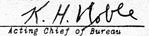
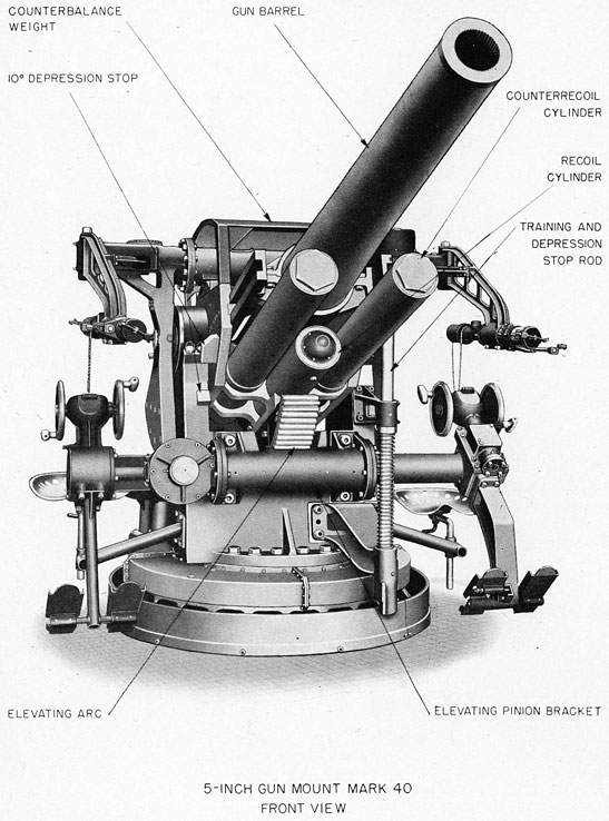
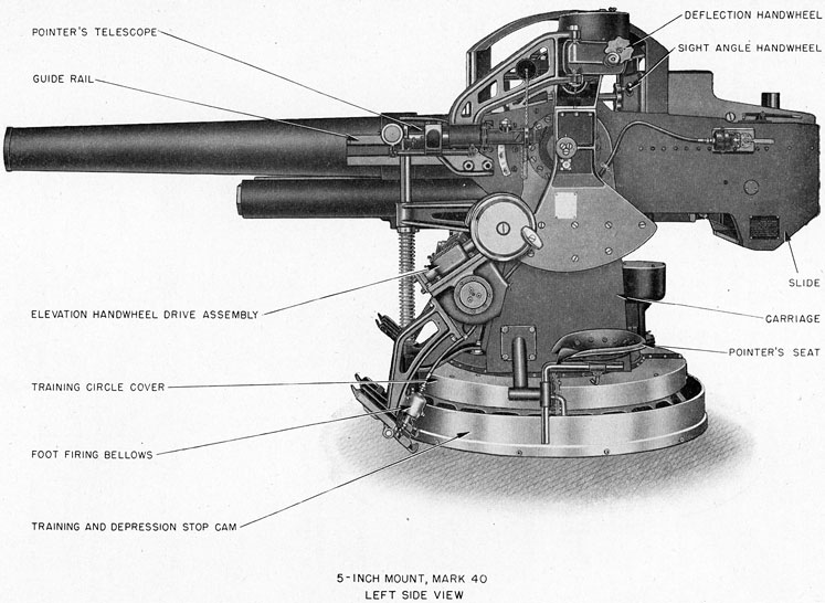
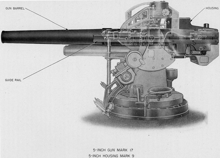
1. The Ordnance assembly described in this book is a new gun mount design for submarine deck installation. It is a single purpose, pedestal type, open gun mount for 5-inch 25-caliber gun. The assembled arrangements are illustrated by plates 1 to 4, inclusive.
2. Functional arrangements. The gun assembly of this mount, together with elements of the slide, comprises a semiautomatic, rapid-fire piece capable of sustained fire of 20 rounds per minute.* It is a gun assembly with semiautomatic sliding breech mechanism, hydraulic recoil and spring counter-recoil systems, arranged for hand loading of ammunition with automatic ejection of the empty cartridge case in counterrecoil. Ammunition is fixed, one-piece, comprising a 53.85-pound projectile and an 11.4-pound case; the powder charge is 9.75 pounds. The initial velocity with service round is 2110 feet per second; maximum range is 14,500 yards.** The assembly is arranged for mechanical percussion firing by the pointer or loader. There is no salvo latch.
3. Ammunition is manually served from the magazine to the gun and is rammed by hand. The breechblock is of the sliding-wedge type which is designed to ensure seating of the projectile and sealing of the powder chamber.
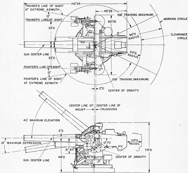
4. Gun elevation and mount train are manually driven from the pointer and trainer stations, respectively. The limits of gun laying motion are from 10° depression to 40° elevation and the maximum train is approximately 316 degrees.
5. Mount foundation. The gun mount foundation consists of a wood platform mounted on top of a cylindrical steel footing in the deck false work above the submarine hull. The holding-down bolts of the stand are embedded in the wood foundation.
6. Components of mount assemblies. The 5-inch Mount Mark 40, is an assembly of 5-inch Ordnance units. The Bureau of Ordnance designations for all components of the mount assembly described in this text are as follows:
* Rate of fire of 22 rounds per minute has been obtained.
** For other ballistic data and references, see page 7.
ORDNANCE ASSEMBLIES OF 5-INCH MOUNT MARK 40
Gun Mark 17 or Mark 17 Mod. 1
Housing Mark 9
Slide Mark 29
Carriage Mark 33
Stand Mark 19
Training Gear Mark 16
Elevating Gear Mark 16
Sight Mark 42 or Mark 42 Mod. 2
Fire Control Equipment:
Telescope (Trainer) Mark 39 any Mod. or Mark 91
Telescope (Pointer) Mark 39 any Mod. or Mark 91
7. These units have design features, mount arrangements, and other characteristics as indicated in the following subparagraphs:
(a) Gun. The gun is a two-piece assembly consisting of a forged tube and a forged liner. It is chambered for fixed ammunition. The bore is chromium plated. The breech shoulder is threaded for bayonet type attachment in the housing.
(b) Housing. This is a right-hand design of a counterbalancing breech assembly which supports the gun assembly in the slide. The housing, together with the gun barrel, forms a semiautomatic piece which, with slide arrangements, comprises a rapid-loading, rapid-firing, semiautomatic gun. It includes a sliding dropblock, case-wedging breech mechanism with breech operating gear. Copper-silicon alloy guide rails are attached to the gun and housing to guide the assembly in recoil and counter-recoil movement in the slide.
(c) Slide. The slide is a box weldment assembly, pivoted on trunnions which are supported in the roller bearings of the carriage. Smaller diameter trunnions, located outside the slide trunnions and integral with the trunnion clips, serve to support the sight assembly and form a pivot for sight elevating movement. Inset bearing strips support and guide the housing and gun assembly during recoil and counterrecoil. The slide assembly also includes the hand lever for manual operation of the
2
PLATE 2
3
breech elements of the firing mechanism, the depression stop bracket, the elevating arc and arc bracket, and the recoil and counterrecoil systems.
(d) Carriage. The carriage assembly consists of the base ring, the carriage roller path, the carriage weldment, elements of the firing mechanism, and the training and depression stop. Trunnion bearings in the cheeks of the carriage weldment provide support for the slide trunnions. The base ring, on which the carriage roller path is mounted, provides the major structure of the rotating assembly.
(e) Stand. The stand is a deck-flange, ring-shaped assembly. It includes the upper and lower roller paths, the annular training circle rack, the
training and depression stop cam, and the training stops.
(f) Training gear. The training gear is a pinion-to-rack drive which is driven by a manual hand-wheel mechanism. The gear-train housings, the handwheel mechanism, and the trainer's seat bracket are bolted to the carriage, and the training circle rack is secured to the stand.
(g) Elevating gear. The elevating gear is a hand-wheel drive through worm, wormwheel and pinion to the elevating arc on the slide. It is mounted on the carriage with handwheels located at the pointer's station in the arrangement illustrated by plate 3.
Fig. 1 - Working Circle
4
Plate 3
5
Plate 4
6
(h) Sight. The sight assembly consists of two optics (pointer's and trainer's) mounted in brackets which are connected by, and pivoted on, a cross tube. Input from the deflection handwheel is received simultaneously and equally by each bracket through individual gear trains operated by worms on the handwheel shaft. The brackets are rigidly connected by the cross tube for movement in elevation; two pinions operating on slide-mounted racks introduce sight angle as the elevation handwheel is turned.
8. Mount design data. The principal data and specification features of the mount are as tabulated below and as indicated in the working circle diagrams of figure 1.
Weight of mount assembly
14,000 lbs.
Gun caliber
5 ins.
Length of bore and chamber
25 cals.
Weight of gun
2,163 lbs.
Ballistic data
see page 7
Chamber pressure, service round
37,500 p.s.i.
Weight of recoiling parts
5,030 lbs.
Trunnion pressure, max., service round
58,025 lbs.
Weight of oscillating parts
8,388 lbs.
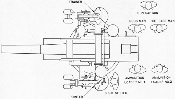
9. Personnel arrangement. Gun crew stations for operation of 5-inch Mount Mark 40 are illustrated in figure 2; minimum crew of eight men is required for normal rapid fire operation.
10. Ballistic data. Ammunition and gun ballistic data and references for 5-inch 25-caliber Guns Mark 17 and Mark 17 Mod. 1 are tabulated in the Gun and Ammunition Data of chapter 2, page 7.
11. Detail descriptions and instructions. Full descriptive information and maintenance instructions for all components of the mount assembly listed in paragraph 7 are given in the chapters following. Chapters 2 to 8, inclusive, contain descriptions, instructions, and references for the gun assembly, slide, carriage, stand, training and elevating gears, and sight. Chapter 9 describes the use of tools and accessories and chapter 10 includes general instructions as to care and maintenance of the mount.
12. Drill machines. Submarine tenders and bases are equipped with 5-inch Loading Machines Mark 20, which are special machines for loading drill. Their use with appropriate drill ammunition prevents unnecessary erosion of the band slope and origin of rifling, as well as "battering" of the gun housing. These machines are described in Ordnance Pamphlet 1126.
Fig 2- Personnel Arrangement
7
Chapter 2 GUN ASSEMBLY 5-INCH GUN MARK 17 OR MARK 17 MOD. 1 5-INCH HOUSING MARK 9
GENERAL DESCRIPTION
1. The gun assembly comprises a 5-inch Gun Mark 17 or Mark 17 Mod. 1 and a 5-inch Housing Mark 9. These form, with the slide, a semiautomatic 5-inch 25-caliber gun assembly of the arrangement illustrated by plate 5. It is a sliding, wedge-type breechblock design equipped with percussion firing device. The assembly is supported in the slide by two longitudinal parallel guide rails, rigidly attached to the gun and housing. These rails ride in guides of rectangular cross section inset in the side walls of the slide. The design prevents rotation in the slide and provides equal travel in recoil and counterrecoil for all positions of gun elevation.
GUN
2. The gun consists of a forged alloy-steel tube and a shrunk-in forged copper nickel liner. The bore of the liner is rifled and chromium plated 0.0005 inch thick. It is chambered for fixed ammunition.* The chromium plating extends for a distance of 102 inches from the muzzle and covers all of the rifling, the projectile band slope, and the forward portion of the powder chamber. The breech shoulder is provided with an interrupted screw thread which engages with a like thread in the gun socket of the housing. The screw threads and breech shoulder are copper plated and are coated with gun-slushing compound when being assembled in the housing. A keyway, one inch wide and one-quarter inch deep, is milled longitudinally in the top of the rear cylinder to receive the gun-and-housing locking key. Guns Mark 17 and Mark 17 Mod. 1 are identical except that the tube for the latter is a radially-expanded Gun Mark 13, bored out to receive liner.
3. Key. The gun-and-housing locking key (fig. 3) prevents rotation of the gun barrel in the housing, and positions the barrel properly at assembly.
* One-piece: 53.85-lb. projectile, with brass-cased service charge 9.75 lbs.
It is a copper-nickel-aluminum alloy piece one-half inch thick, one inch wide, and 3.80 inches long. An integral lug at its front end, for attachment to the housing by a one-half inch cap screw, has a tapped holt for a jacking-out screw.
4. Two clearance recesses are milled, 180° apart, in the breech face at the cartridge rim seat. They permit the extractor levers of the breech mechanism to move forward of the breech face, and thus remain in engagement with the case rim as the breech is closed.
5. Assembly arrangement. The provisions for assembly of the barrel to the housing permit regunning the mount without dismantling the breech mechanism, slide, or other parts. Full details as to preparation and sequence of operations for regunning are prescribed in the disassembly routine of paragraph 38.
6. Gun and ammunition data for all gun assemblies.
Gun barrel:
Length, overall
125.0 ins.
Diameter, breech shoulder
11.440 ins.
Diameter, rear cylinder
11.497 ins.
Diameter, muzzle cylinder
8.030 ins.
Weight (without housing)
2163.0 lbs.
Center of gravity (from breech face)
52.49 ins.
Powder chamber:
Length
28.25 ins.
Diameter at breech
5.38 ins.
Diameter at band slope
5.16 ins.
Volume
431 cu. ins.
Rifling:
Length
98.113 ins.
Grooves and lands
45
Twist
right, uniform, one turn in 25 cals.
Chromium plate (from muzzle)
102.0 ins.
Projectile travel
103.03 ins.
Ammunition:
Projectile (5-inch AA Common, Mark 36):
8
Plate 5
9
Weight
53.85 lbs.
Length
4.14 cals.
Fuze
Mechanical Time Fuze, Mark 18
Cartridge case (Mark 4, Mod. 2):
Weight, powder charge
9.75 lbs.
Weight, complete
21.15 lbs.
Primer
percussion
Ballistics (Service):
Initial velocity
2110 ft./sec.
Maximum range
14,500 yds.
Range table
Sk. 108389
HOUSING
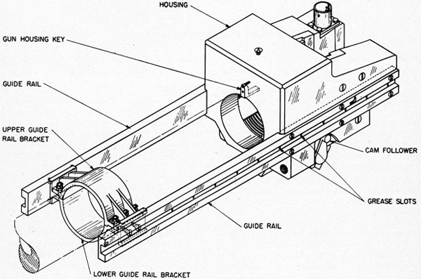
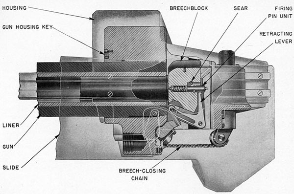
7. Housing Mark 9 is a gun mounting and breech assembly unit which includes the breechblock, firing mechanism, and guide rail subassemblies shown in figure 3. These units, assembled and mounted with the gun barrel in the slide, function to open and close the gun breech; to seat, fire, and extract cartridge cases; and to support and guide the travel of the piece in recoil and counterrecoil. The components of the housing are described in the text below in the sequence of the following list of subassemblies:
8. The main element of the housing assembly is an irregular block-shaped steel forging of the form and arrangement indicated in figure 4. It is 30 inches long and 20.75 inches across its parallel side faces. The forward portion is machined to provide the bore and interrupted screw thread in which the breech shoulder and rear cylinder of the gun barrel are assembled. Immediately to the rear of the screw threads, a broached vertical breechblock way extends through the housing from top to bottom providing mounting and operating space for the breechblock and breechblock guides. A trough-like space, aligned with the front bore, is machined in the rear portion of the housing to act as an ammunition tray. Three tapped holes in the lower part of the front face receive the locking sleeves of the recoil and counterrecoil piston rods. Longitudinal
Fig. 3-Housing and Guide Rails
10
Fig. 4-Breech Assembly-Vertical Section
rectangular slots are machined in the parallel side faces of the housing to hold the guide rails which support the housing in the slide. Two lugs on the bottom provide bearings for the breechblock operating shaft, which extends across the bottom of the housing just in front of the breechblock way. A third lug, between the first two, acts as a stop to limit the rotation of the operating shaft. A vertical bore from top to bottom of the right rear section forms a space for the breech mechanism operating spring and its housing.
9. Breechblock guides. The two breechblock guides (pl. 6) are aluminum-bronze forgings. They are machined for a force fit in the sides of the breechblock way and are secured by cap screws. A kidney-shaped slot cut through the lower front section of each guide carries an extractor lug, and a drilled hole extends from the rear face of the guide to the kidney slot to receive a spring-loaded extractor plunger. A rectangular slot, in which the breechblock operates, extends from the top to the bottom of each guide. These slots are inclined
slightly from the vertical to provide a wedging action as the breechblock closes.
Guide Rails
10. Two rectangular aluminum bronze guide rails, shown in figure 3, are secured to the gun housing and to steel brackets clamped around the gun. The steel cap screws which fasten the rails are cadmium plated and chromium dipped. The rails are mounted with their longitudinal axes 0.375 inch below, and parallel to, the centerline of the gun. Each rail is 80 inches long, 5 inches wide, and 1.75 inches deep, and has a rectangular slot, 2.01 inches wide and one inch deep. These slots extend the full length of the rails to form bearing surfaces for the bearing strips in the slide which support the gun and housing assembly. The vertical face of each guide rail slot is provided with 11 vertical grease slots, spaced 5.6 inches apart, interconnected by a longitudinal groove, to ensure uniform lubrication of the bearing surfaces. Longitudinal grease slots are cut in the horizontal bearing surfaces.
11. The breech mechanism (pl. 7*) is of the vertically sliding, wedge-block type which has mechanically semiautomatic action in loading, firing, and gun recoil-counterrecoil. Initial opening of the breech is accomplished by a manually actuated lever on the slide but, during firing, hand operation is used only in the event of failure of the semiautomatic feature. The assembly operates to seat the cartridge case when closing the breech, to eject the case when opening the breech, and to hold the breechblock down until a case has been loaded into the gun. These functions are performed by the components of the breech mechanism, described below in the following sequence:
Breechblock
Operating shaft
Operating spring
* The extractors and extractor plungers have been omitted from this plate for clarity of other details. They are shown on plate 8.
Operation of the mechanism as a whole is described in paragraphs 25 to 27, inclusive.
12. Breechblock. The breechblock (pl. 6) is a 122-pound forging of copper-nickel alloy, and is machined on all surfaces. It wedges the cartridge case and seals the gun breech when closed and, as it opens, operates the cartridge case extractors. Its parallel side faces have rectangular ribs, inclined slightly from the vertical, which slide in the breechblock guides. Forward of the ribs, slots are provided to receive the inner lugs of the extractors. Two transverse bearings, in the bottom of the block, position the retracting lever which cocks the firing mechanism. A recess between these bearings provides a working space for the lower arm of the retracting lever, and for the center crank arm of the operating shaft. Inclined slots are machined through the block adjacent to this recess to receive
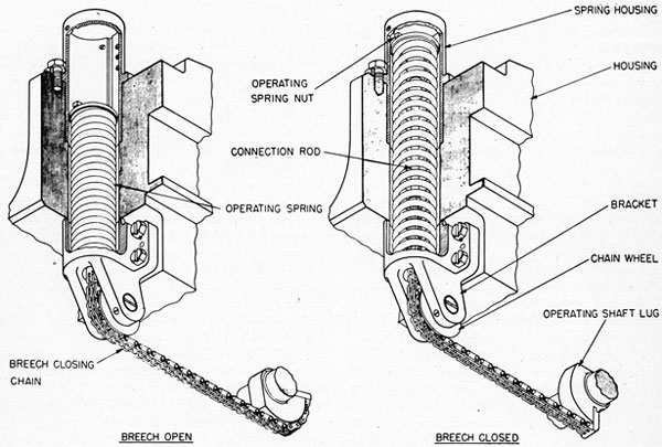
Fig. 5-Breech Operating Spring
12
the bearing blocks which translate the rotating movement of the operating shaft into vertical movement of the breechblock. A shallow trough in the top of the block is continued to the rear in the attached extension tray, to form a cradle for the projectile and cartridge case in loading. A bore from the front to the rear face, and a transverse bore connecting therewith, provide housings for the firing pin mechanism and the sear, respectively.
13. Operating shaft. The operating shaft (pl. 7) is a 27-pound forging of copper-nickel-aluminum alloy, mounted in transverse bearings on the bottom of the housing. An integral, lever-type lug on the left end of the shaft engages, in counterrecoil, a cam attached to the slide to turn the shaft and, through it, actuate the breechblock. A cam-type lug on the other end of the shaft engages with the hand-operating mechanism for manual operation of the breech mechanism. A center crank-arm lug is machined to form a fork with drilled, transverse bearings which support the bearing block pin. A fourth integral lug, to the right of the center crank arm, forms a cam attachment for the breech closing chain.
14. Operating spring. The operating spring (fig. 5) is a coil spring located in a spring housing which fits into the vertical bore in the right rear section of the gun housing. The spring housing is a hollow cylinder with a square flange about midway of its length for attachment to the top face of the gun housing. A bracket attached to the bottom of the gun housing forms a continuation of the bore and carries a wheel which guides the breech closing chain. A shoulder in the bore of the bracket forms a seat for the lower end of the spring. The operating spring nut bears on the top of the spring, and is screwed onto a connecting rod whose lower end is pinned to the chain. The other end of the chain is pinned to a connecting piece which is attached to the cam lug on the operating shaft. Thus rotation of the shaft to open the breechblock compresses the spring and provides energy for raising the block. Initial compression of the spring, obtained by adjusting the connecting rod in the nut, regulates the closing of the breech. Two diametrically opposed lugs on the nut ride in slots in the spring housing to keep the unit from turning. Vertically spaced holes in the upper part of the spring housing permit the insertion of a rod to hold the spring in compression during assembly or disassembly. A rod
inserted in the upper set of these holes prevents the spring assembly from flying out if the chain or rod should break.
15. Bearing blocks (pl. 6). Two pentagonal bronze blocks are mounted on the ends of the pin in the center crank arm of the operating shaft. These blocks are free to turn on the pin as they slide in inclined slots in the bottom of the breechblock. As the shaft turns, movement of the blocks in the slots translates the rotary motion of the shaft into vertical movement of the breechblock.
16. Cam plate (pl. 7). A flat plate, attached by means of a vertical pivot to the inside of the slide, acts with the cam follower on the operating shaft to actuate the breech mechanism. The rear edge of the plate is cut as a cam, along which the follower operates in counterrecoil. A slanting surface is machined on the face of the plate opposite the position of the follower when the gun is in battery. This allows the follower to rise as the breechblock is closed, and also to force the plate back against the slide. A coil spring between the plate and the slide forces the cam out again when the follower clears the end of the plate during recoil. The cam plate may be retracted for single round fire by inserting a 1/2-inch bolt through a hole in the left side of the slide and screwing the bolt into a tapped hole in the plate.
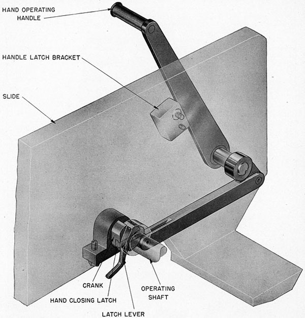
17. Breech hand-operating mechanism (fig. 6). A hand lever, pivoted on the right face of the slide, operates a crank through a link to engage the lug on the right-hand end of the operating shaft when the breechblock is closed. Movement of the lever to the rear and down thus opens the breech against the compression of the operating spring. As the crank does not engage the lug for closing the breech in normal operation, the hand lever is free to be returned to its forward position where it is held by a non-positive, spring-loaded detent (pl. 2) during automatic operation of the breech. A sliding latch in the crank may be positioned, through a manually operated lever, to engage the operating shaft lug for manual closing of the breech if the operating spring fails. Figure 6 illustrates the latch in this position with the breechblock in the closed position. When the breech is thus closed it is important that the hand operating handle be returned all the way to its stowed position before the gun is fired. After manual closing of the breech it is not necessary to disengage the sliding latch by pulling
13
Fig. 6-Breech Hand-Operating Mechanism
aft on the latch lever, since disengagement is automatically accomplished during counterrecoil.
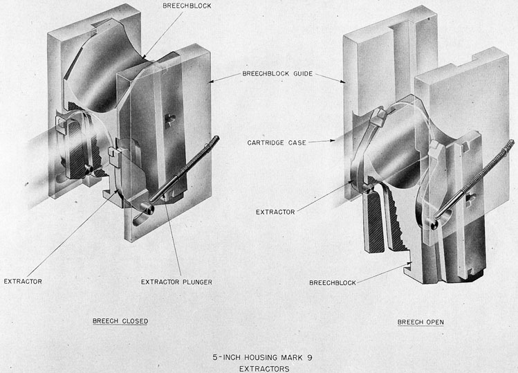
18. Extractors. The extractors (pl. 8) are right and left steel elements (identical but of opposite hand) located, one on each side of the breechblock, in spaces formed by the breechblock guides and corresponding recesses in the block. They are actuated by downward movement of the block to eject a
cartridge case, and have the additional function of holding the block in the open position until they are tripped by the ramming of a case. A cylindrical lug on one side of the extractor fits into a kidney-shaped slot in the corresponding breechblock guide. Spring-loaded extractor plungers in cylindrical bores in the breechblock guides push these lugs forward in the slots. A cam-shaped lug, eccentric
14
PLATE 8
15
Fig. 7-Breech Firing Mechanism
with the first, on the other side of the piece, rides in a slot in the side of the breechblock.
Firing Mechanism
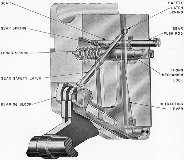
19. The firing mechanism (pl. 9 and fig. 7) actuated by the breech mechanism retracts and cocks a firing pin, and fires cartridge primers by percussion when actuated by a foot-firing device. The mechanism consists of components described in the following sequence:
Firing pin unit
Retracting lever
Sear
Sear safety latch
Sear push rod
20. Firing pin unit (pl. 9). This unit consists of a chromium-molybdenum alloy steel firing pin, a firing spring, a bearing ring, a bronze lock, a steel cocking sleeve and cocking handle, and a safety latch. The assembly is secured in the longitudinal bore in the breechblock by the firing mechanism lock, which forms a casing for the unit and has two radial lugs engaging a groove in the breechblock. The firing pin shaft carries the firing spring and spring bearing ring, the cocking sleeve, and the cocking handle. This assembly is held together as a unit
16
by a nut threaded on the end of the firing pin shaft which takes up against the cocking handle body. The nut is locked by a cotter pin and permits adjustment of the firing spring. On the top of the cocking sleeve is a vertical lug of rectangular cross section, which is free to move longitudinally in a slot in the firing mechanism lock. It is held in the cocked and latched positions by the sear and safety latch, respectively. The cocking handle is a sleeve with a vertical lug extending downward into the path of the toe on the retracting lever. It has two cocking-tool grab hooks at the rear to permit manual cocking or latching. The safety latch, secured by a screw to the lock, is manually swung into position to engage a cutout section in the forward end of the cocking handle sleeve. When so positioned, the latch holds the firing pin retracted from the sear.
21. Retracting lever. The retracting lever (pl. 7) consists of a bell crank lever with its arms extending from its fulcrum axis. It is mounted on a shaft which is free to turn in the transverse bearings in the bottom of the breechblock. Its lower arm extends beneath the breechblock into the fork of the center crank arm on the operating shaft. The central part of the bearing block pin (par. 15) rides in a cam slot in the lower arm to transmit relative motion between the crank on the operating shaft and the breechblock to the retracting lever. The upper arm of this lever extends upward at the rear of the breechblock and has a toe which engages the vertical lug of the cocking handle of the firing pin unit. Thus movement of the bearing block pin in the cam slot of the lower arm, when the breech is opened, shifts the retracting toe and the firing pin rearward to cock the mechanism.
22. Sear. The sear (pl. 9) is a straight rod extending, through a drilled hole, horizontally from the left side of the breechblock across the longitudinal bore of the firing pin unit. Its end is seated against a compressed coil spring which positions a notch in the sear in front of the cocking sleeve lug when the firing pin unit is cocked, and thus holds the firing pin in the cocked position. A slot in the sear, contiguous with the notch, allows the cocking sleeve lug and firing pin to move forward when the sear is pushed to the right against the sear spring. The sear is kept from rotating by a lug on its outer end which rides in a slot in the breechblock.
23. Sear safety latch. An annular groove in the
sear is engaged by a lug on the sear safety latch to lock the sear in the cocked position while the breechblock is open. This latch is a rod, extending upward from the bottom of the block, which seats against a spring in the block. The spring positions the lug of the latch in the annular groove of the sear until the latch is pushed upward by the operating shaft center crank arm as the breech closes, and thus disengages the sear.
24. Sear push rod. To fire the gun, the sear is pushed clear of the firing pin cocking sleeve by a rod which operates in a drilled hole in the gun housing and left guide rail. Both the end of this rod and the end of the sear which it engages have specially machined edges which function to ensure that engagement will occur only when the breech is fully closed. The outboard end of the push rod is engaged by the firing plunger of the foot firing device mechanism. Its end surface has similar special form which functions to prevent engagement except when the gun is completely in battery.
OPERATION
25. A cycle of operation of the breech and firing mechanisms in semiautomatic action, commencing with the gun loaded, breechblock closed, and firing mechanism cocked, is illustrated on plates 7, 8, and 9 and described in the following subparagraphs:
(a) The foot-firing device (described in ch. 3) actuates the sear push rod to force the sear out of engagement with the firing pin cocking sleeve lug (pl. 9). This permits the firing spring to snap the firing pin, cocking sleeve, and cocking handle forward with sufficient force to detonate the percussion cap of the cartridge primer.
(b) A recoil and two counterrecoil cylinders (described in ch. 3) serve to limit the gun recoil and return the gun to battery.
(c) As the gun recoils, the lug on the end of the operating shaft (pl. 7) wipes rearward across and off the inside face of the cam plate, clearing and releasing it. The cam plate spring then forces the cam plate out into the path of the counterrecoil movement of the lug. This is the only action of the breech mechanism in recoil.
(d) In counterrecoil, as gun and housing approach the battery position, the lug engages the end surface of the cam plate. Continued forward movement of the housing forces the lug to follow the cam (lower) surface and thus to rotate the operating shaft.
(e) As the operating shaft turns, the bearing blocks, carried by the center crank arm, pull the breechblock down. These blocks turn on their supporting pin as they slide in the inclined slots in the block, and thus transform the circular motion of the center crank arm into the straight-line motion of the breechblock.
(f) Rotation of the operating shaft against compression of the operating spring (fig. 5) stores up energy in the spring, and this energy is subsequently used to raise the breechblock.
(g) The circular motion of the bearing block pin in the slotted arm of the retracting lever, combined with downward motion of the breechblock, moves the retracting lever toe to the rear to engage the vertical lug of the firing mechanism cocking handle. The slot in the lower arm of the retracting lever is shaped to cause a quick initial movement of the firing pin with respect to movement of the breechblock. This prevents shearing of the pin or scoring of the primer base.
(h) As the retracting lever moves the cocking handle to the rear, the firing spring is compressed and the vertical lug of the cocking sleeve slides through the slot in the sear. When the lug clears the slot, the sear spring forces the sear to the left to hold the firing pin unit in the cocked position, and the sear safety latch is forced down by its spring to lock the sear in place.
(i) Further rotation of the operating shaft and downward motion of the breechblock causes the bearing block pin to ride on the lower surface of the retracting lever slot, and thus moves the toe of the retracting lever forward out of engagement with the cocking handle.
(j) During the downward movement of the breechblock, the inner extractor lugs ride in the slots in the sides of the block (pl. 8*). The slots allow the extractor lugs to be given a slight initial movement to "start" the cartridge case. Thereafter, movement of the lugs is prevented, and the outer lugs are held in the rear of the kidney-shaped slots in the breechblock guides, until the block nears the end of its downward movement. At this point, the forward curved portion of the breechblock slots forces the inner lugs rapidly downward and forward onto the pallets as the spring-loaded extractor plungers force the outer lugs forward in the kidney
* The extractors and extractor plungers have been omitted from plate 7 for clarity of other details.
slots. Final movement of the block, combined with the forward movement of the extractor lugs, causes the curved front edges of the extractors to act as movable pivots as they turn against the breech face. This gives the upper ends of the extractors rapid straight-line movement toward the rear and ejects the empty cartridge case.
(k) When the inner extractor lugs move forward on the pallets, they act to hold the block down against the compression of the operating spring. As this occurs, the lug on the operating shaft moves clear of the cam surface and comes to rest below the slanting cut on the inside face of the cam plate. Thus the lug is no longer held down by the cam, but cannot move upward as long as the breechblock is held open by the extractors. This condition is illustrated on plate 7, "breech open." The lower half of the breechblock has been cut away in this illustration to show details of the operating parts.
(l) Ramming of a cartridge case pushes the tops of the extractors into the recesses in the breech face, and thus forces the inner extractor lugs back across the pallets into line with the vertical slots in the breechblock. This allows the breechblock to be raised by the operating spring, acting through the operating shaft and the bearing blocks.
(m) As the operating shaft turns, the lug rotates upward across the slanting cut in the cam plate and forces the plate back against its spring.
(n) As the block reaches its closed (raised) position, the center crank arm pushes the sear safety latch out of engagement with the sear, the latter is brought into alignment with the sear push rod, and the gun is again ready to fire when the loader operates the safety latch described in paragraph 19, chapter 3.
26. Initial opening of the breech. This is accomplished by the hand-operating mechanism (fig. 6). Such operation of the breech mechanism, in opening, is identical with that of semiautomatic operation except in the method of forcing the operating shaft to rotate. In manual operation, the hand-operated crank engages the lug on the right end of the operating shaft to turn it, whereas in semiautomatic operation the energy of the gun counterrecoil is used for this purpose, as described in paragraph 25. After opening the breech, the hand-operating lever is returned to its forward position where it is held by its non-positive, spring-loaded latch.
27. Hand closing of breech. In the event of failure
18
of the operating spring, the breech must be closed by hand. To accomplish this, the manual breech operating hand lever must be moved to the "breech open" position. Then the hand-closing latch must be moved to the engaged position by reaching under the slide and moving the latch lever, shown in figure 6, forward by hand. In this position, the latch will engage a flat surface on the operating shaft lug and enable the breechblock to be raised by the manual breech operating lever.
MAINTENANCE AND OPERATING INSTRUCTIONS
28. General instructions. The gun barrel, breech mechanism, and the attached parts of other units are to be operated and maintained in accordance with the regulations of the Ordnance Manual, the directions of instruction plates on the assemblies, and the instructions of this chapter. The importance of proper care, complete regular servicing, and frequent, thorough inspection cannot be overemphasized.
29. Breech mechanism operating casualties. These are usually due to one of the causes discussed in the subparagraphs below. Maintenance, care, and operating precautions to prevent or remedy each class of casualty are prescribed in separate, lettered paragraphs following each designated case.
(a) Jamming of the breechblock. The is generally caused by foreign matter or by "seized" parts of the breech mechanism. Occasionally, it may be due to an oversize cartridge case. If there is a slight jam of the block when closing, it may be forced by light taps with a rawhide mallet; greater force should not be applied except in emergency. In such emergency, special precautions shall be taken to clear all unnecessary personnel from the vicinity.
CAUTION: Forcing the block in either direction may result in a serious accident from firing of the charge when the breechblock is not in the fully closed position. The block must not be forced to either open or close unless it can be ascertained positively that there is no projecting metal on the face of the breechblock, nor any foreign matter between the face of the breechblock and the base of the case which might, in any way, be wiped or drawn across the base of the primer. In case of a jam before the base of the primer has been covered, the block may be lowered without danger of dragging
across the base of the primer. If the base of the primer has been covered, lowering of the breechblock introduces a reversal of motion which may be extremely dangerous. Forcing the block closed may result in galling parts of the mechanism, and thus put the breech mechanism out of commission until repairs can be made. Each case is individual and, therefore, a careful study must be made to determine the safest method of procedure. Nothing in these instructions is to be construed in any way as affecting the provisions of Article 927 (63) (3) of U. S. Navy Regulations, which prohibit the opening of a breech within 30 minutes after the last attempt to fire.
(b) Stiffness of operation. This may be caused by the galling or scoring of any of the operating parts of the breech mechanism, but such damage will usually be found on the cam plate and cam follower of the operating shaft, or blocks and block guides. Examination of the cam plate and operating shaft cam follower can be made by feeling. after removing the grease from the camming surface of the plate. If the surface feels rough, it has galled. If the cam plate has galled, the follower will usually be found to have galled also. Scoring may be removed by stoning, but in the event of galling the affected parts must be replaced.
(c) Improper lubrication. Casualty due to improper lubrication will occur if lubrication is inadequate, or if a substitute lubricant has been used. The most satisfactory lubricant for breechblock operation is that covered by O. S. 1165. See paragraph 32 for directions as to use of this lubricant.
(d) Failure of breechblock to latch open. If the breechblock fails to remain in the open position after counterrecoil, the pallets and extractor lugs should be inspected for excessive wear. If the pallets are worn, they must be replaced with a new set -it is not possible to refit worn pallets.
30. Maintenance precautions. The following are prescribed for general maintenance care of these assemblies:
(a) The guide rails of the gun-housing assembly, the breechblock ways, and all parts of the breech mechanism must be kept clean, free from corrosion, grit, and gummed lubricant.
(b) Do not deface, alter, or paint over the legends on name and instruction plates.
(c) Special tools, spanner wrenches, open-end wrenches, etc., are provided for servicing, for
Change 1 - Page 2
PREVENTION OF CASUALTIES TO BREECH MECHANISMS
OF 5"/25 AND 5"/38 CALIBER MOUNTS
1. Reports of recent 5-inch breech mechanism casualties indicate the most prevalent causes to be material failures, loss of adjustments, wear and galling of parts, lubrication difficulties, and faulty ammunition. The information given herein concerns procedures considered effective in reducing occurrences of breech mechanism casualties, and is offered for guidance.
2. Breech Closing Mechanism Casualties. Failures of breech operating springs, spring connecting rods, chains, and chain connections can be minimized by careful and frequent adjustment checks of the operating spring tension. The operating spring should first be so adjusted that when compressed with the breechblock lowered, there is just sufficient energy to close the breech slowly at zero degrees gun elevation when a dummy cartridge (weighted to service weight and fitted with a wooden plug) is rammed. One more turn (occasionally two) of the spring connecting rod into the spring nut is then added to obtain a good working adjustment whereby the breech closes smartly on the dummy cartridge case.
(a) The ".68 setting of the operating spring nut, noted on the instruction plate (Dwg 133768-8), is recommended for an initial trial adjustment. This setting may be readily obtained by screwing the spring connecting rod into the operating spring nut until the rod rear end is flush with the rear face of the nut, and then backing the rod out seven and one-half turns. Due to the condition of wear and variations in the breech mechanism parts, it is often desirable to further adjust the operating spring tension either way from the ".68 initial setting. One vessel has used operating spring settings varying from ".312 to "1.312, and reported no material failures in 26,418 total rounds fired on its fourteen guns, except for one breech closing spring failure attributed to a burred breechblock and housing. (The ".312 to 1".312 range of settings when compared to the ".68 value represents extremes of screwing the spring connecting rod approximately four turns further into the operating spring nut or backing it out of the nut approximately seven turns from the ".68 initial setting.)
(b) The proper operating spring tension may also be judged by experience from the sound of breechblock closure, and should be determined while using the power rammer. The breech operating hand lever may be used as an additional check. If tension is too great, the lever tends to drag the operator toward the latch position. When tension is satisfactory, the lever (when released from the midpoint position) will go to forward position and engage the latch smartly. If tension is too light, the hand operating lever fails to latch, often stopping at mid-position.
(c) A new straight type spring connecting rod (Dwg 253519-1) has been approved to supersede the helical type rod (Dwg 133768-3) in new manufacture. The straight type rod has proven satisfactory in extended recent firing tests and is considered less susceptible to breaking or taking a permanent set. However, the helical type spring rods are not obsolete, and may be expected to have long service life if excessive operating spring tensions are avoided. The length of the operating spring and the spring connecting rod should be regularly checked, and the rod should be replaced when significant permanent set has occurred. It is to be noted that the design does not permit the operating spring to be compressed solid even when the spring rod is screwed as far as possible into the operating spring nut.
(d) Care should be exercised when adjusting the rammer buffer in order to relieve the breech operating spring as much as possible from the work of forcing the cartridge case home. The rammer pressures for 5"/38 singles are 650 p.s.i. maximum and 600 p.s.i. minimum, with the desired setting of the relief valve at 630 p.s.i. The rammer pressures for 5"/38 twins are 850 p.s.i. maximum and 790 p.s.i. minimum, with the desired setting of the relief valve at 830 p.s.i.
(e) Keeping the breechblock in its open position as a readiness measure, and over-tensioning the operating spring to insure complete closure, are believed to contribute considerably to material failures. It is also probable that the use of heavy breechblock lubricants tends to facilitate the collection of debris and foreign material in the breech mechanism and contributes to excessive drag on the operating spring, resulting in breechblock stoppages. Frequent applications of breechblock lubricant OS 1165 (OS 1350 Grease is permissible in climates where OS 1165 dissipates rapidly) to prevent galling, and early replacement of unsatisfactory operating springs, connecting rods, and other component parts, is recommended.
PAGE NUMBER
OP 100
Page 12 after paragraph 33
OP 553 (3rd Rev.)
Page 32 after paragraph 35
OP 589
Page 22 after paragraph 39
OP 700
Page 23 after paragraph 10
OP 735 (1st Rev.)
Page 44 after paragraph 23
OP 745
Page 15 after paragraph 10
OP 748
Page 17 after paragraph 38
OP 805
Page 21 after paragraph 10
OP 868
Page 36 after paragraph 32
OP 895
Page 18 after paragraph 10
OP 1013
Page 28 after paragraph 22
OP 1029
Page 19 after paragraph 32
Change 1 - Page 3
3. Breech Operating Spring Assembly and Disassembly. When it is necessary to remove the operating spring from the operating spring housing, the following simplified procedure that requires no spacing links or special tools is recommended:
(a) Lower the breechblock by the hand operating lever, thereby compressing the spring.
(b) Insert a pin in the 3/8-inch drilled holes in the spring housing behind the spring nut.
(c) Close the breechblock and engage the salvo latch. Disconnect the chain connection from the operating shaft and turn the connecting rod out of the spring nut until there is engagement of approximately four threads between the parts. To insure that there is an engagement of four threads, the connecting rod should first be disassembled from the nut and then reassembled, turning the rod four turns after initial engagement of the threads.
(d) Connect the chain connection to the operating shaft, trip the salvo latch and lower the breechblock slowly by the hand operating lever, thereby compressing the operating spring slightly.
(e) Remove the pin behind the spring nut.
(f) Close the breechblock with the hand operating lever, and engage the salvo latch.
(g) Disassemble the spring nut from the connecting rod. The spring may then be removed from the spring housing.
(h) For reassembling the spring, reverse the above procedure.
4. Paint in the Breech Mechanism. Painted witness lines are considered desirable for indicating "gun in battery" and "breech completely closed." The use of paint on any other sliding or bearing surfaces in the breech mechanism should never be permitted.
5. Galled Operating Shafts and Cam Plates. Attention is invited to Ordalt 1143 which substitutes operating shaft cam plates embodying an overlay of aluminum bronze, in place of steel cam plates. Accomplishment of Ordalt 1143 is particularly recommended in 5"/38 mounts showing appreciable galling of the cam plates. Attention is further invited to Ordalt 2011 which provides for the use of a modified operating shaft and the installation of flanged operating shaft bushings to reduce galling between the operating shaft thrust surfaces and the side walls of 5"/38 housings. Accomplishment of Ordalt 2011 helps to minimize sluggish breech operation, and may readily be performed by ships' forces upon receipt of the bronze bushings.
6. Breechblock Guides. Occasional occurrences of a cracked 5"/38 breechblock guide in service have been noted in aluminum bronze guide plates of early manufacture. A cracked guide plate should be replaced when practicable, but has ordinarily had no effect on gun performance. A cracked guide plate was deliberately broken in two pieces, replaced in the housing, and fired 5000 rounds satisfactorily at the Naval Proving Ground. If a cracked aluminum bronze guide plate is replaced with a steel guide plate, tests have shown that no adverse effects are to be expected. Improvements in manufacture are such that guide plates of recent manufacture are not believed susceptible to cracking. Ordalt 2019, which provides for drilling access holes in the slide, should be performed at the first removal of cracked breechblock guides so that future replacement of guide plates may be accomplished without removing the housing from the slide.
7. Breech Jams - Miscellaneous Information. The following precautions are recommended for keeping the occurrence and seriousness of breech jams at a minimum:
(a) Use all practicable care in handling cartridges to avoid denting the cases.
(b) Steady the projectile and cartridge in the tray before ramming, to assure smooth entrance into the gun.
(c) Do not attempt to ram a cartridge known to be dented or deformed; one known to have an undersize, oversize, or loose cork plug; or one which has been extracted after a failure to seat.
(d) Extract promptly any cartridge which does not permit closure of the breech block except by light taps of a rawhide maul on the block. Forcing the breech closed is likely to result in a tight jam. Extracting and using a fresh cartridge, will minimize delay in resuming fire.
(e) Do not leave a live projectile in a hot gun bore any longer than absolutely necessary. If impossible to fire the projectile out, cool the barrel with fire hoses both inside and out, keeping personnel clear of the gun as well as possible when danger of a "cook-off" exists. "Cook-offs" in 5"/38 guns have occurred in 34 minutes, after 167 rounds at 10 r.p.m.; and in 98 minutes, after 120 rounds intermittent fire.
(f) Short cartridges (described in NAVORD OCL A72-43) for clearing guns, also "crowbar-and-chain" type cartridge case extracting tools (described in NAVORD OTI G9-44) for extracting jammed cartridge cases should be kept available at the guns for prompt application.
Change 1 - Page 4
8. Breech jam Clearance Procedure. The following generalized steps are recommended as effective in clearing most types of breech jams and loading casualties wherein the breech does not close:
(a) Shift to local control (keep gun trained on a safe bearing).
(b) If breechblock is within two inches of complete closure attempts to close it with light taps of a rawhide maul are permissible.
(c) Engage the breech operating lever latch, then use the hand lever to assist closure of the breech, and if it still refuses to close -
(d) Open the breech with the breech operating hand lever.
(e) Use the "crowbar-and-chain" cartridge case extractor as necessary to extract, and throw the extracted cartridge over the side.
(f) Unload the gun with the special short cartridge. But, if the breech cannot be opened, and the gun is hot
(g) Cool the gun barrel with fire hoses directed down the muzzle, on the outside of the barrel, and on the breech mechanism.
(h) Clear the mount of all personnel.
9. Misfire Procedure. The following generalized steps are recommended as effective in clearing most types of misfire:
(a) Attempt to fire by local battery (several times).
(b) Attempt to fire by percussion (further attempts to fire electrically are usually ineffective after the first percussion blow).
(c) Shift to local control (keep gun trained on a safe bearing).
(d) Check the firing cut-out mechanism, then recock the firing mechanism and attempt to fire by percussion.
(e) Check firing pin mechanism safety latch, then replace the firing pin mechanism and attempt to fire by percussion.
(f) When in combat, wait (20) seconds after the last attempt to fire, then open the breech and throw the misfired cartridge over the side. (The possibility of a hangfire of more than (20) seconds duration exists but is very remote.)
(g) Unload the gun with a short clearing charge.
Note: In practice firing, guns should not be sufficiently hot to produce cook-offs, hence the standard 30-minute waiting period before opening the breech must be observed.
10. Miscellaneous Breech Casualties. Firing failures have sometimes been caused by the bronze
bearing blocks (Dwg 116018-4) being incorrectly installed in the slotted ways of the breechblock. These bearing blocks must be oriented with the bevelled edge forward and downward (oil holes up and aft), since they strike the breech face of the gun when installed inverted. Such interference can restrain the operating shaft from attaining the fully locked position (although the breechblock appears completely closed), thereby preventing the sear safety latch from releasing the sear and also preventing the retracting lever from allowing the firing pin to contact the primer for electric firing. An incorrectly installed bearing block may be readily detected by sighting along the breech face from above and noting its protrusion, after closing the breech on an empty powder chamber. Other firing failures are caused by sluggish firing pin mechanisms, possibly due to the use of heavy lubricants. Most firing pin mechanisms have been modified in accordance with Ordalt 1707, which generally opens up the clearances of the firing pin parts to prevent binding in percussion firing. Ordalt 1707 has been accomplished on any firing mechanism whose firing pin cocking handle (Dwg 134991-3) bears the revision letter "N" or later. Lubrication with light mineral oil is recommended for maintaining the firing pin mechanism in satisfactory operating condition.
19
assembly, and for disassembly; these tools, and no others, are to be used in such maintenance. (See ch. 9.)
(d) Never operate the breech mechanism with the operating spring disconnected; to do so may wreck the assembly. Maintain the spring in the load adjustment indicated in paragraph 35.
(e) Perform the exercise and tests specified in paragraphs 31 to 33, inclusive.
(f) Follow the directions in paragraph 31 before loading and firing the gun assembly.
31. Preparation for firing. The following servicing, testing and checking operations should be performed in sequence, prior to loading and firing the gun assembly:
(a) Check all lubrication.
(b) Open the breech by hand and check the action to see that it is normal, particularly the firing pin retraction.
(c) Ram a dummy cartridge case, and depress the foot-firing pedal. Check the breech-closing and firing pin movements to see that they are normal.
(d) Open the breech by hand for initial loading and return the hand operating handle to the stowed position.
(e) Before loading the gun, verify that the safety latch is set, or reset this latch (located at the left rear of the gun slide) to prevent firing until the first loader is clear of the recoiling parts. (A special mechanism to permit manual resetting is under design at date of publication. See footnote to par. 26 in ch. 3 for temporary device.) Improper adjustment and/or premature operation of the safety latch may result in firing of the gun upon breech closure and possible injury to the first loader.
The safety latch is intended to prevent firing of the gun until the first loader has stepped clear of the recoiling parts, at which time he should- operate the latch lever permitting the gun to be fired at will, or causing the gun to fire if the foot pedal is held depressed. If the safety latch lever is operated prior to loading, the gun may fire on breech closure and the recoiling parts strike the first loader. The safety latch is automatically reset by gun recoil for succeeding rounds, so that manual resetting or checking of the safety latch setting is necessary prior to the first round only.
32. Lubrication. All parts of these assemblies must be lubricated according to the frequency and with the lubricants specified on the lubrication
charts appended, and in accordance with the instructions of chapter 10. Lubricants other than those specified, if used as temporary substitutes, must be completely removed from the parts when the correct material is replaced. The use of substitute lubricants at certain points (notably the breechblock guides) may result in erratic performance and damage. Before applying the special lubricant specified for the breechblock guides, the block and the guideways should be cleaned thoroughly. The lubricating compound should be completely washed from all parts of the breech assembly with the appropriate petroleum solvent at least once every two months, and then the parts wiped with a clean cloth saturated with alcohol.
33. Care of the gun barrel. As indicated in the descriptive text, the breech shoulder and rear cylinder are copper plated. This provision against corrosion is supplemented at assembly with a coat of gun-slushing compound, applied hot. Replenishment of that coating during the life of the barrel is not essential, but is possible by means of a Zerk gun applied to the grease fitting located on the top of the housing near the front end. The chromium-plated bore and the chamber surface to the rear of the plated area must be kept coated at all times (except during firing) with a film of light mineral oil, applied with clean toweling wrapped on the bristle bore sponge. Replenish this film weekly. After firing, the gun bore should be cleaned as soon as practicable, gauged to indicate any constrictions, cleared of constrictions, and oil-coated. Ordnance Circular Letter G25-44 of 17 May 1944 discusses the care and preservation of gun bores, including the following procedure.
(a) Clean the bore with one of the following:
(1) Laundry-soda solution (1 lb. laundry soda to 4 qts. water, preferably hot). Then rinse the bore and chamber with fresh water and dry with clean toweling.
(2) Diesel oil, or light lubricating oil. If oil is used, vigorous swabbing should be employed, preferably with cloth-wrapped sponges, for mechanical removal of powder residue.
(3) A caustic soda solution (3 oz. caustic soda to 4 qts. water, preferably hot) may be used for cleaning gun bores, but is ordinarily unnecessary and must be handled with caution because it can seriously injure skin and clothing, and is particularly injurious to the eyes.
20
(b) Pass the bore gauge if possible. If it passes freely, oil the bore, unless decoppering is to be accomplished.
(c) If the bore gauge will not pass freely, remove steel (very unlikely) or copper constrictions with emery abrasive, a wire brush, or an approved decoppering tool. Emery should be used sparingly, and only by experienced personnel, to avoid excessive removal of metal from the liner. Rinse, dry, and oil the bore.
ADJUSTMENTS
34. The gun barrel and housing assemblies described in the preceding text are of such design that, when installed as shown on their general arrangement drawings, they do not require adjustment of parts other than prescribed in paragraphs 35 and 36.
35. Breechblock operating spring (fig. 5). The breechblock operating spring should be so adjusted that, when compressed with block lowered, it has just sufficient energy to lift the block and wedge a case. The spring tension may be varied as follows:
(a) Close the breech.
(b) Unbolt the operating spring housing.
(c) Pry the housing up until it can be rotated in its seat.
(d) Turn the spring housing clockwise (looking down) if it is desired to increase the spring compression; turn in the opposite direction if less compression is desired. Secure the spring housing in place.
(e) Screw the spring connecting rod into or out of the nut to change the adjustment as desired. [Change 3]
36. Firing pin spring (fig. 4). This spring should be so adjusted that the firing pin will protrude 0.075 inch beyond the front face of the breechblock when the pin is in the fired position. This adjustment is correct when the travel of the pin forward from the cocked to the fired position is 0.85 inch. The adjustment may be determined and corrected as follows:
(a) With the breechblock in the closed position, are the firing pin cocked, measure the distance from the front. front face of the vertical lug on the cocking handle to the rear face of the block. The measurement should be 0.88 inch.
(b) Depress the foot-firing pedal to release the firing pin, and repeat above measurement. It should be 0.03 inch.
(c) If adjustment is found to be necessary, withdraw the cotter pin from the threaded end of the
firing pin and slack off or take up the castellated locknut to obtain the correct adjustment. Replace the cotter pin.
DISASSEMBLY AND ASSEMBLY
37. General instructions. With the exception of the firing mechanism and elements of the breech-operating gear, which must be disassembled for inspection after firing, the gun assemblies do not ordinarily require disassembly during the accuracy life of the gun barrels. Disassembly and assembly of most parts are apparent from a study of the general arrangement and detail drawings; other parts are disassembled and assembled as described in the following paragraphs.
38. Gun replacement. The regunning operation is best performed by removing the gun and housing from the slide, as a unit, to deck of tender or repair ship or to shore base shop. The open rear end of the slide design facilitates withdrawal from the mount; the operation does not require extensive dismantling but does require home yard or repair ship crane, crane attachments and personnel familiar with such work. The usual method of disassembling 5-inch bayonet-joint guns, unlocking the gun from the housing while installed in the mount, cannot be accomplished with conventional assembly-disassembly clamp mounted on the gun due to interference of other parts of the mount. The preferred regunning routine is as follows:
(a) Position the gun at 0° elevation, trained to port or starboard for convenient rearward sliding-out movement.
(b) Place substantial cribbing beneath the rear end of the slide.
(c) Remove breechblock shell tray extensions so that a sling can be attached around the loading tray.
(d) Attach sling to chase of gun.
(e) Lubricate the guide rail and housing ways.
(f) Uncouple recoil and counterrecoil rods.
(g) Slide the gun assembly rearward to remove it from the slide. During this operation it is necessary to shift slings several times before the gun assembly can be removed.
(h) Support the assembly on special cribbing.
(i) Disassemble the guide rails and the breech mechanism.
(j) Remove the gun and housing locking key.
(k) Attach the special clamp (sk. 79760 or sk.
21
PLATE 10
22
111881) furnished for unlocking the barrel. Unlock the gun from the housing.
(l) Withdraw the gun forward from the housing onto horizontal skids using wire pendant.
39. Installation of gun in housing. To install a gun in the housing follow the disassembly procedure in the reverse order with the following variations.
(a) With barrel supported for sliding in, place the wire pendant through the bore and secure it at the muzzle end. Pass the free end through the housing to a chain fall mounted on adjacent structure. Before drawing the gun into the housing, clean the rear cylinder, threads and the bore of the housing and coat them with hot gun-slushing compound.
(b) After installing gun-housing key, force gun-slushing compound O. S. 627 through the fitting in the top of the housing until compound exudes at the front of the housing.
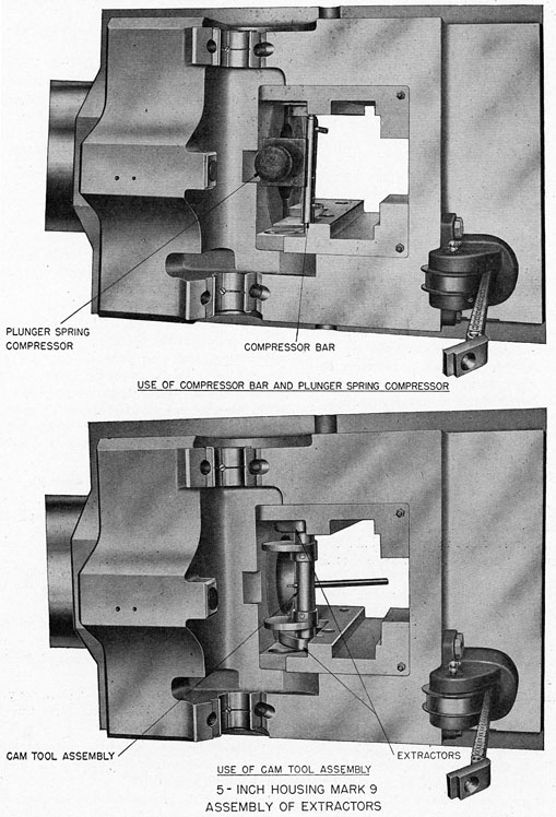
40. Disassembly of the breech mechanism. To facilitate assembly and disassembly of the breech mechanism certain special purpose tools are provided. These serve to assemble or to retain elements of the block assembly during removal or installation of the block. They are designated:
Compressor bar assembly
Plunger spring compressor
Cam tool assembly
They are used as indicated in the disassembly instructions in the following subparagraphs, and the assembly instructions of paragraph 41.
(a) Withdraw the firing pin assembly.
(b) With the breechblock up, trip the hand closing latch to engage the crank at the right end of the operating shaft.
(c) Remove the operating spring housing.
(d) Rotate the operating spring nut counterclockwise (looking down) until all the compression is taken off the spring.
(e) In this position the breechblock is supported only by the hand-closing latch.
(f) Unshackle the chain from the operating shaft.
(g) Pull the chain and connecting rod out of the housing.
(h) Screw dismounting tool 8-Z-911-13 into the tapped hole in the top center of the breechblock.
(i) Lower- the block until it can be supported by the breechblock support 8-Z-956-1 which is placed in the housing projectile trough beneath the shell-tray extension.
(j) Remove the operating-shaft bearing caps and swing the shaft clear of the bearings.
(k) Remove the bearing bushings.
(l) Remove the pin from the center of the retracting lever.
(m) Drive out the retracting lever shaft, piece 253510-2, through the breechblock extension.
(n) Slip the bearing blocks, 253510-3, forward in the slots in which they operate, then draw the retracting lever down and rearward to free the lever and shaft assembly from the breechblock. The bearing blocks thus come out of the bottom of the slotted ways.
(o) Push out bearing block pin, piece 253510-4.
(p) Attach the cam tool assembly to hold the extractors in closed position, as shown on plate 10.
(q) Lift the breechblock out of the housing.
(r) Remove the extractors, extractor springs, and plungers.
(s) Remove the sear and sear spring.
(t) Pull out sear safety latch and latch spring. If dismantling of the operating spring assembly is not required, omit operations (b) through (g) and proceed as follows: Open the breech manually. Insert a 3/8-inch rod through the two holes in the spring housing immediately above the spring nut. Close the breech manually. Unshackle the chain from the operating shaft. Proceed with disassembly operations (h) through (t).
41. Assembly of the breech mechanism. In performing the routine below, the special tools required are those designated in paragraph 40 and those called for on Naval Gun Factory List No. 20228. (See pls. 22 and 23, ch. 9.)
(a) Place the sear spring in the sear hole.
(b) Place the safety latch spring in the safety latch hole.
(c) Insert the safety latch, aligning its slot to clear the sear hole.
(d) Place the sear in place, securing it by manipulating the sear safety latch.
(e) Insert the two assemblies of extractor plunger springs and plungers into their respective holes, after greasing the plungers.
(f) Insert the pin ends of the compressor bar in the hole of each extractor plunger. The tool position is shown on plate 10.
(g) Thrust the plunger spring compressor up between the compressor bar and the breech face as shown on plate 10.
23
PLATE 11
24
(h) Place the two extractors in position and remove the plunger spring compressor and the compressor bar.
(i) Place the ends of the cam tool over the extractor lugs and rotate the cam until the largest radius of the cam presses against the breech face.
(j) Enter the breechblock into the housing using the dismounting tool and lower it until it rests on the extractor lugs.
(k) Remove the cam tool.
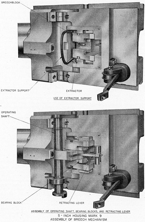
(l) Insert the extractor support as shown on plate 11. Set the breechblock support in place beneath the shell tray extension.
(m) Holding the breechblock up with the dismounting tool, pull the lower end of the extractor support towards the gun muzzle until the inner extractor lugs can enter the slotted ways in the block.
(n) Lower the breechblock until it rests on its support and remove the extractor support.
(o) Insert the slotted arm of the retracting lever in the fork of the operating shaft center crank arm, and install the bearing block pin.
(p) Place the bearing blocks on the pin and orient each as shown on plate 7.
(q) Hold the operating shaft transversely below and to the rear of the breechblock; with retracting lever forward on the pin, enter the bearing blocks into their slotted ways.
(r) Insert the retracting lever shaft through the breechblock extensions and the retracting lever pivot bearing.
(s) Secure the shaft with the cotter pin.
(t) Place the half-bearing bushings in the housing lugs.
(u) Place the operating shaft journals in the bearings.
(v) Assembly the other halves of the shaft bearings in place. Insert the lockscrews.
(w) Hold the breechblock up by means of the hand-operating mechanism. Place the operating spring in its housing and run the chain down through the spring and the chain-wheel bracket.
(x) Turn the chain connecting rod in the spring nut until the chain can be fastened to the operating shaft. Turn the spring nut until all slack in the chain is taken up.
(y) Place the operating spring housing over the spring, entering the nut in the housing keyways.
(z) Rotate the spring housing clockwise (looking down) to compress the spring; three full turns give correct spring compression. Bolt the spring housing in place.
(aa) Verify correct spring adjustment as outlined in paragraph 35.