A. How to cut cable to length and prepare for pulling
1. Introductory information
Cables are always shipped on reels with size and type marked
on the reel. The reels are set on cable jacks or horses so
that they will turn freely. The worker can then reel off
cable and cut to any length desired. Under no condition
must the cable be twisted, bent sharply, or kinked.
2. Supplies, tools, and equipment
Proper size and type of cable
Cable jacks or horses
Length of proper size pipe
Hacksaw
Screw driver
Rule
3. Procedure
a. DETERMINE FROM THE BLUEPRINT THE PROPER SIZE AND TYPE
OF CABLE FOR THE RUN.
b. SELECT A CLEAR SPACE IN WHICH TO REEL OFF THE CABLE.
c. ROLL THE REEL OF CABLE TO ONE END OF THE CLEARED SPACE.
1) Put a pipe through hole in the center.
2) Jack up on cable jacks or horses.
3) Put a mark about three feet in front of the reel
and from this mark measure off the desired length.
4) Mark the space off in five-foot lengths.
5) Pull off free end of cable and reel it out to the
proper mark.
d. CUT OFF AT THE BEGINNING MARK IN FRONT OF THE REEL.
(USE HACKSAW FOR CUTTING.)
Note: If the cable is to be carried some distance to
the job, it should be rolled up again into a roll
and the two ends tied to the roll with a piece of
marlin.. On the job it should be unrolled and
laid out straight before starting the pull in.
e. PREPARE ONE END OF THE CABLE FOR PULLING IN BY FORCING
BACK SEVERAL INCHES OF THE ARMOR WITH A SCREW DRIVER.
18
A. How to cut cable to length and prepare for pulling (continued)
1) Cut off the remaining lead and cable with a hacksaw.
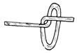
f. PULL THE ARMOR BACK OVER THE END AND TWIST TO A POINT
IF IT IS TO BE PUSHED IN.
1) If it is to be pulled in, form the armor into an
eye and tie a rope into it.
Note: Small cables are pushed in, and larger cables
are pulled in.
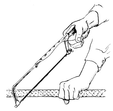
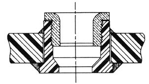
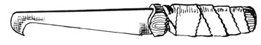
4. Illustration
a. The proper method of cutting cable by hand.
19
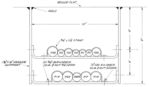
B. How to rack cable and strap it in place in cable hanger
1. Introductory information
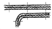
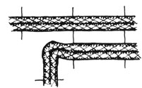
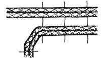
All cables in any one run are laid parallel. Special care
should be taken not to damage the cable in any way. Small
cables may be bent to a radius of two diameters and the
larger cables should be bent to a radius of eight diameters.
(See accompanying illustrations.) Regardless of size, all
the cables in one run must be bent to conform to the largest
cable. Do not bend the cables sharply away from packing
or stuffing tubes. (See illustration on page 35, Chapter V.)
They must come through the tube straight for at least one
inch before beginning the bend. Cables must not cross one
another.
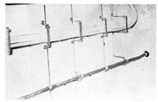
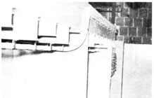
Overhead View of Cable Run
Side View of Above Cable Run
Showing Bend
20
B. How to rack cable and strap it in place in cable hanger (continued)
21
B. How to rack cable and strap it in place in cable hanger (continued)
2. Supplies, tools, and equipment
Soft-headed hammer
Wood prybars
Rope or marlin
3. Procedure
a. SKID ONE END OF CABLE. (SEE INFORMATION ON "HOW TO SKIN
CABLE" PAGES 45 - 50 INCLUSIVE.)
1) Enter it into stuffing tube of outlet box.
b. BEGINNING AT ONE END, DETERMINE TAE ORDER IN WHICH
CABLE WILL BE LAID.
c. FORCE ALL THE CABLES UP BETWEEN THE FIRST HANGING LUGS.
1) Bolt hanger into place.
d. CONTINUE ALONG THE RUN UNTIL ALL CABIES ARE IN THE RACKS.
e. START AT THE FIRST HANGER AGAIN AND SEE THAT EACH CABLE
CONES OUT OF ITS STUFFING TUBE STRAIGHT.
1) If any offset is to be made, make it about one inch
from the tube.
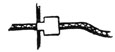
f. SECURE THE CABLE OR CABLES IN PLACE IN THE FIRST HANGER
WITH A CABLE STRAP FASTENED TO THE HANGER WITH MACHINE
SCREWS.
g. IF ANY CABLE OR CABLES BREAK AWAY 1,',ROM THE MAIN RUN,
BEND THEM TO THE PROPER RADIUS FOR THE LARGEST CABLE
THE RUN.
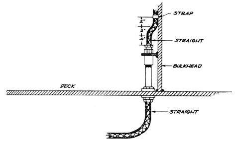
h. OFFSETS FOR DECK OR BULKHEAD TUBES SHOULD BE MADE AS
IN THE ABOVE PROCEDURE.
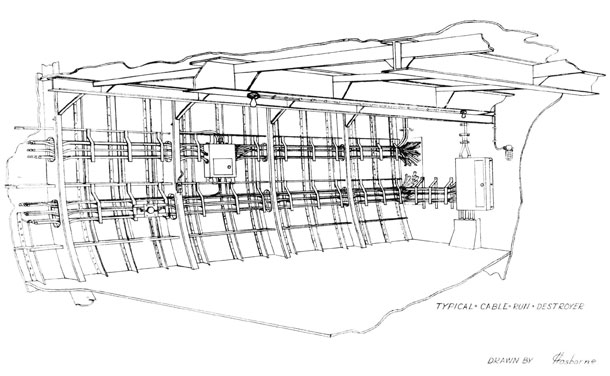
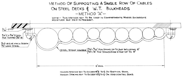
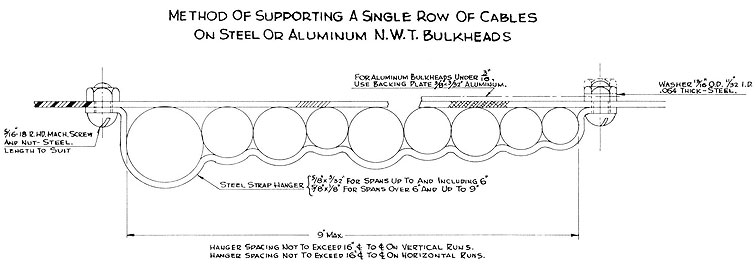
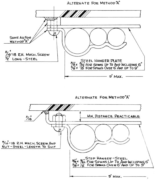
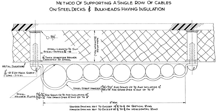
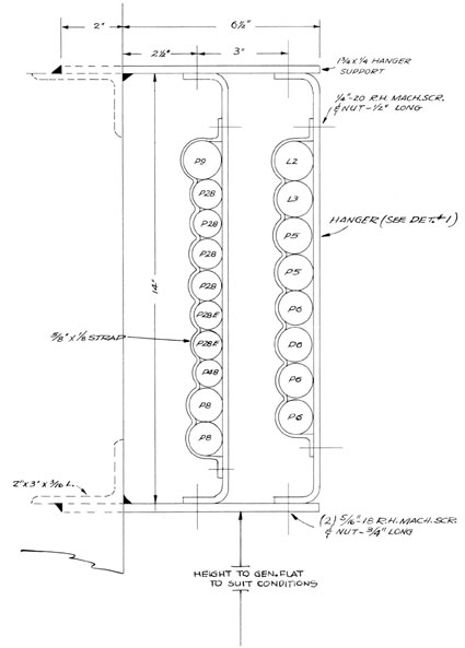
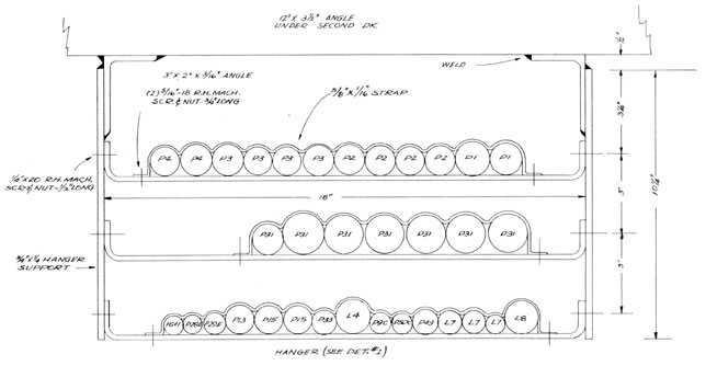
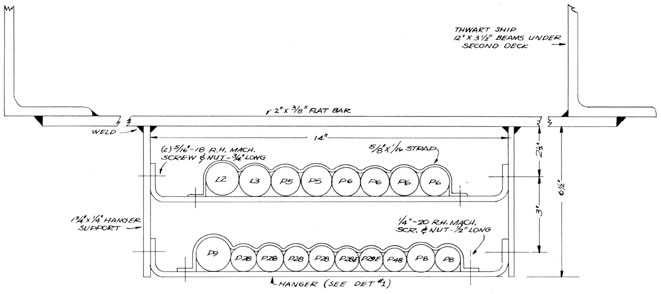
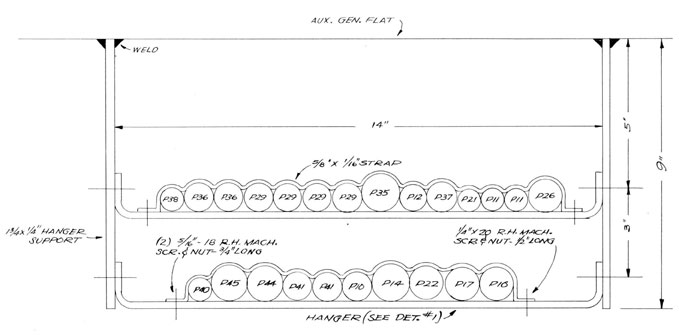
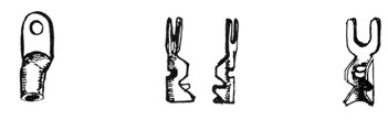
4. Illustrations
The following are some types of hangers used in marine
wiring; these include Section 1--single racks, and Section 2--double and triple racks (as required by specification of
the job).
22
B. How to rack cable and strap it in place in cable hanger (continued)
a. Section 1
23
B. How to rack cable and strap it in place in cable hanger (continued)
24
B. How to rack cable and strap it in place in cable hanger (continued)
25
B. How to rack cable and strap it in place in cable hanger (continued)
26
B. How to rack cable and strap it in place in cable hanger (continued)
b. Section 2
27
B. How to rack cable and strap it in place in cable hanger (continued)
28
B. How to rack cable and strap it in place in cable hanger (continued)
29
B. How to rack cable and strap it in place in cable hanger (continued)
30
B. How to rack cable and strap it in place in cable hanger (continued)
31
C. How to form and strap cable
1. Objectives
a. To point out the factors to be considered in forming
and strapping cable.
b. To show how to form and strap cable.
2. Introductory information
After all cables in a particular rack have been pulled in
and racked, the cable is ready to form and strap.
3. Supplies, tools, and equipment
Rubber mallet
Channel locks
Screw driver
Drift
6" crescent wrench
Pry
Straps
Machine screws (if clearance holes are used)
Nuts
Drill (either a tap size or clearance drill for bolt that
is to be used. If straps are to be bolted, use clearance
drill.)
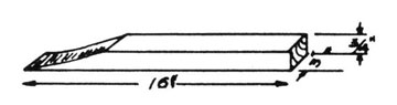
Rope, 6 feet and 3/8 inches long (if cable is larger than 3/0)
A piece of hard wood 16 inches long, 3/4 inches thick, and
3 or 4 inches wide, which is tapered on one end.
4. Procedure
a. ASCERTAIN FROM WHICH POINT THE STRAPPING IS TO BE
STARTED.
1) Strapping may be started at some given point and
strapped both directions from the point, or may
be started at one end of the run and strapped
through to the other end.
2) Never start strapping from both ends and work toward
the center, for this procedure would cause an
accumulation of slack, and there would be no
possibility of disposing of it.
32
C. How to form and strap cable (continued)
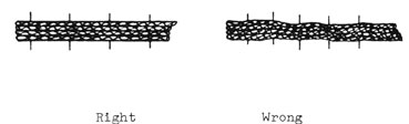
b. DRILL HOLES IN SPREADER TO SECURE STRAPS.
1) See that the holes are located in such a manner
that when the strap is fastened the cable will
lie in a straight line.
Note: In illustration above of wrong method the
holes are not drilled in the proper line;
therefore the cable is not lying straight.
Before cinching a strap tight, all waves
in the cable should be worked out.
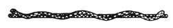
c. LOOK AT CABLE RACK FROM THE SIDE.
1) Waves illustrated below will always be apparent.
2) These waves can be worked out by tapping with the
rubber mallet on the peak of the bend.
3) In some instances it is necessary to hold a flat
board against the opposite side of the cable in
order to make the cable flex. The 16" hard wood
will generally suffice.
d. THE SLACK GAINED IN THIS PROCESS MUST BE WORKED IN THE
DIRECTION THE STRAPPING IS BEING DONE.
e. WAVES IN THE HORIZONTAL PLANE MUST ALSO BE WORKED IN
THE DIRECTION THE STRAPPING IS BEING DONE.
1) At this point, if the rack has some cables that
are a great deal more rigid than others, it is best
to shape the rigid cables first.
2) If the lighter cables are straightened first, they
are likely to be pushed out of shape in the process
of shaping the stiffer cables.
33
C. How to form and strap cable (continued)
3) Because there are a number of cables side by side
in the rack, it is not practical to try to get the
waves out by means of the rubber mallet alone.
f. USE TAPERED END OF HARD WOODWORKED BETWEEN THE CABLE.
1) Do the hammering on the wood.
2) If the cable to be straightened is the third or fourth
cable from the outside, do not hammer on the outside
cable to straighten it. This may damage the outside
cable before you straighten the other cable.
3) Never hammer a cable hard enough or long enough in
one place to flatten it, because this might result
in serious damage to the insulation and sheathing
as well as ruin the appearance of the job.
4) For the same reason, do not use a metal-faced
hammer.
g. A GOOD BEND SHOULD BE MADE IN THE CABLE WHEN A POINT IS
ENCOUNTERED WHERE THE CABLE IS TURNING INTO THE RACK OR
OUT OF IT.
1) A bend with a radius equal to eight times the
diameter of the cable should be made.
2) If there are different sized cables, the stiffer
cables should be shaped first and the lighter
cables shaped to fit the stiffer cables.
3) The bend should be shaped in such a manner that it
does not distort the shape in the rack. (See the
following illustrations.)
34
C. How to form and strap cable (continued)
Right procedure
Wrong procedure
Bend throws cable out of line before it leaves rack.
Wrong procedure
Bend is too abrupt. It is likely to damage insulation or armor. It does not show neat workmanship.
h. PUT AT LEAST ONE STRAP ON THE BRANCH RUN TO HOLD SHAPE
OF BEND WHEN COMPLETED.
1) Continue one strapping of the main run unless
instructed differently.
i. WHEN ENCOUNTERING A BULKHEAD, PASS THE CABLES BEYOND
IT THROUGH THE STUFFING TUBES.
1) Shape from the last hanger to tube in such a way
that the cable is on the same plane as the tube.
Right
Wrong
35
C. How to form and strap cable (continued)
Note: In illustration showing wrong method, the cable,
in entering the tube so abruptly, does not lend
itself to easy access of the tube for packing,
nor does it permit proper finishing of packing
tube with white lead.
2) Along the path of the cable there may be places
where one or more cables are to go through the
deckhead inside of kickpipes. Never assume that
any cable will be all right in any kickpipe that is
of proper size, for invariably there is a definite
cable to enter a specific kickpipe.
j. USE A ROPE OR PRY WHERE A BEND IS TO BE MADE ON HEAVY
CABLE.
1) This will make the process much easier. The method
of applying the pry or rope will depend upon prevailing conditions.
k. CONTINUE THIS PROCESS UNTIL CABLE IS STRAPPED FROM ONE
EXTREMITY TO THE OTHER.
1. CABLE MUST ENTER KICKPIPE STRAIGHT.
1) Cable that breaks out of a kickpipe must be kept
straight for about 3 or 4 inches; then it should
break against the bulkhead. (See illustration
below.)
36
D. How to pack tubes
1. Objectives
a. To point out factors to be considered in the packing
of tubes
b. To show how to pack tubes
2. Introductory information
The packing of tubes consists of few details, but is in
itself a very important job.
In most instances the packing of a tube calls for a water-tight job.
3. Supplies, tools, and equipment
Channel locks
Hammer
Packing tool
Knife or pliers
Improvised fishing tool or screw driver
White lead
Packing
4. Procedure
a. BACK PACK-NUT OUT OF TUBE AND FASTEN ON CABLE, OUT OF
THE WAY.
b. LIFT OUT PACKING RING.
Note: This usually can be accomplished by hooking with
a narrow-bit screw driver. If the ring fits too
closely around the cable, it may be necessary to
flatten an end of a piece of wire and use it for
a fishing tool.
c. AFTER THE RING HAS BEEN FISHED OUT, FASTEN IT OUT OF
THE WAY.
Note: The tube is now ready for packing. The size of
the packing will be governed by the size of cable
and tube. In most cases 1/4-inch and 3/8-inch
packing is used.
d. MEASURE LENGTH OF THE PACKING TO BE USED BY PUTTING ONE
TURN AROUND THE CABLE.
1) Cut this turn about 1/16 inch shorter than the
circumference of the cable.
Note: If the packing is cut the same length as the
circumference of the cable, the ends will lie
as shown in illustration.
37
D. How to pack tubes (continued)
This creates a condition that makes it almost
impossible to start the pack-nut when the proper
amount of packing is in the tube.
When the packing is cut slightly short, the ends
will lie flat as shown below.
If the proper size of packing is used there will
be room for two to three rings of packing in each
tube.
e. PUT EACH RING OF PACKING IN SEPARATELY BY MEANS OF
HAMMER AND PACKING TOOL.
f. CUT PACKING WITH EITHER A KNIFE OR PLIERS.
g. PLACE PACKING IN SUCH A WAY THAT THE CUT ENDS OF ANY
TWO RINGS ARE NOT TOGETHER.
Note: When the packing tool is being used, great care
should be taken to prevent damaging of the
threads on the inside of the tube.
h. PUT PACK RING IN POSITION AFTER THE PROPER AMOUNT OF
PACKING HAS BEEN PLACED.
38
D. How to pack tubes (continued)
Note: The starting of the pack-nut can be made much
easier if the pack ring is set by driving with
the packing tool and hammer. Care must be
taken in starting the pack-nut in order that
the threads are not crossed. If nut tightens
with two or three twists of the nut, one may
assume that the threads are crossed and the
nut should be backed off and started over. The
threads are fine; as they are made of brass, they
damage very easily. A pair of channel lock
pliers is a good tool to use for tightening the
pack-nut.
If the proper amount of packing is used in
filling the tube, the nut should be tight before it screws all the way down. (See illustrations below.)
There should be 1/8-inch to 3/16-inch space
between nut and tube when the pack-nut is
tight on the packing. (See illustration.)
If the nut is tight on tube it is impossible
to tell whether nut is tight against packing
or tube.
39
D. How to pack tubes (continued)
i. AFTER THE PACK-NUT IS TIGHT, FILL GROOVE BETWEEN NUT
AND CABLE WITH WHITE OR RED LEAD. THIS WILL MAKE A
WATERTIGHT JOB.
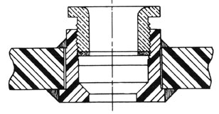
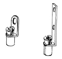
5. Illustrations
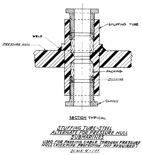
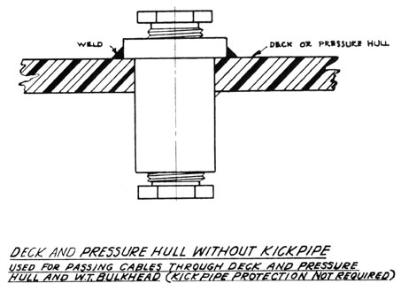
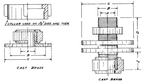
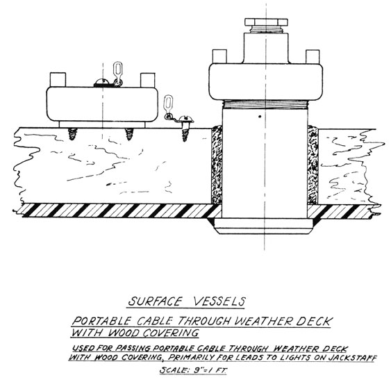
The following illustrations show various types of stuffing
tubes used in marine electrical wiring:
40
D. How to pack tubes (continued)
Deck and Bulkhead Flanges
41
D. How to pack tubes (continued)
42
D. How to pack tubes (continued)
Stuffing Tube
Terminal Tube
43
D. How to pack tubes (continued)
44
E. How to skin cable
1. Introductory information
The outside sheath of cable must be removed before the
individual wires can be terminated. Care must be taken
to cut the cable the proper length.
Caution: It must not be cut too short.
2. Supplies, tools, and equipment
Hacksaw
Rule
Line or side-cutter pliers
Cable-skinning tool (patented or linoleum knife)
Friction tape
Screw driver
3. Procedure
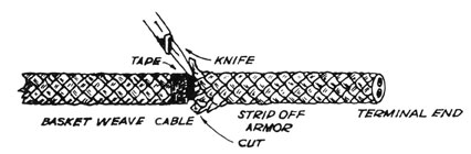
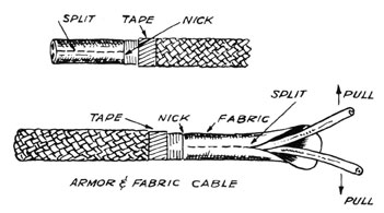
a. ARMOR FABRIC-COVERED CABLE
1) Wrap a turn or two around the cable to serve as a
marker and to keep the armor from fraying.
2) Cut through the armor.
3) Do not cut too deep.
4) Lift armor at cut with screw driver and strip off
by grasping at cut and pulling towards terminal
end. (See illustration.)
5) Make a cut around the cable with the knife about
1/4 inch to 1/2 inch from the armor. This cut
should be no more than two-thirds through the fabric.
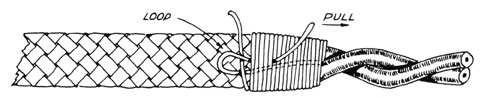
6) Pull the skinning knife or tool lengthwise of the
cable and skin out the wires. Sometimes the wires
can be skinned out for a few inches at the end and
pulled in opposite directions. (See accompanying
illustrations.)
45
E. How to skin cable (continued)
Note: Do not make the cuts too deep as it is very
easy to nick the insulation on the wires.
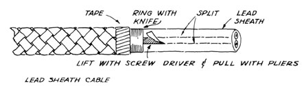
b. ARMOR LEAD-COVERED CABLE
1) With the skinning tool, ring the lead sheath about
1/4 inch to 1/2 inch from the armor and split towards the end.
2) Make another split about 1/4 inch to 1/2 inch from
first split. This forms a strip running lengthwise
of the cable.
3) Break the lead at the ring by moving back and forth.
4) Pry up the strip with a screw driver and pull out
with pliers.
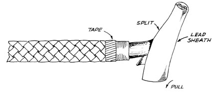
5) Sometimes the lead may be taken off with one split
as shown in illustration below. Start the opening
with. a screw driver.
46
E. How to skin cable (continued)
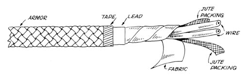
Note: Do not cut through the armor as this may
injure the wire underneath.
c. UNWIND THE FABRIC TAPE UNDER THE LEAD.
1) Cut off jute packing at the end of the lead or
fabric sheath. (See illustration.) This jute is
placed in the cable to make it hold its round shape
and to serve as protection.
47
E. How to skin cable (continued)
d. OTHER TYPES OF ARMORED CABLE ARE HANDLED IN MUCH THE
SAME WAY AS DESCRIBED.
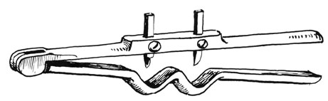
e. DIFFERENT TYPES OF SKINNING TOOLS ARE ILLUSTRATED BELOW:
Cable Skinning Knife
Tool for Ringing and
Stripping Marine Cable
48
E. How to skin cable (continued)
End View
Side View
Cable Skinning Tool (2 Views)
49
E. How to skin cable (continued)
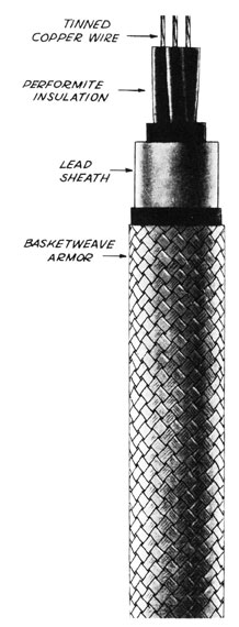
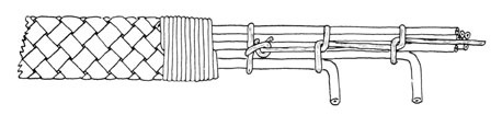
f. A STANDARD-TYPE MARINE ARMOR CABLE, CUT SECTIONALLY
TO SHOW CONSTRUCTION, IS ILLUSTRATED BELOW:
50
F. How to serve and lace cable
1. Introductory information
Any cable that terminates in the open and is therefore
subject to damage should be served or laced, or both.
In open switchboards it is desirable to insulate the
cables by serving from the point of entry to the terminal
lugs and laceing it into a form. Varnished cambric insulation, and types of insulation that may unwind and leave the
conductor bare, should be served for protection.
2. Supplies, tools, and equipment
Diagonal pliers
Lacing twine
Tape
3. Procedure
a. PREPARE THE CABLE AS DESCRIBED IN SKINNING CABLE.
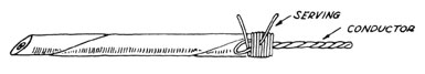
b. LAY ONE END OF LACING TWINE ALONG THE CABLE.
1) Wrap back the cable from the wire towards the
armor and over it.
2) Be sure the twine is held tight. (See illustration.)
c. DOUBLE BACK THE EXCESS TWINE THAT WAS LOOPED UNDER
THE WRAPPING IN ORDER TO FORM A LOOP.
1) Take five or six more tight wraps and run the end
through the loop.
2) Pull the loop under the wraps until the end is held
securely. (See illustration.)
3) Tape wrapped under serving helps to make a smooth
job.
51
F. How to serve and lace cable (continued)
d. VARNISHED CAMBRIC INSULATION IS SERVED IN THE SAME WAY
AS ORDINARY CABLE. (SEE ACCOMPANYING ILLUSTRATION.)
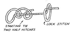
e. LACING CABLE FORMS IS ACCOMPLISHED BY A LOCK STITCH
AS SHOWN IN ILLUSTRATION BELOW.
1) The starting tie is two half hitches taken around
the line.
2) Do not use a half hitch for lacing as this tie is
apt to come loose. (See illustration.)
3) The accompanying illustration shows a typical form
with conductors broken out for termination.
52
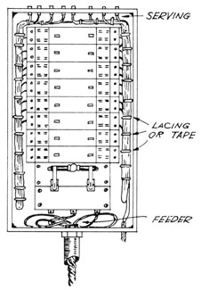
F. How to serve and lace cable (continued)
4) The illustration below shows how cable is laced in
a panel.
Note: Tape can be used for lacing. (Sometimes
it is required.)
53
G. How to connect and hook up cable
1. Objectives
a. To slow the necessity of tight and solid connections
b. To show the proper method of preparing wire for
soldering
c. To make good electrical connections
2. Introductory information
The process of connecting wires together or connecting lugs
to wires is done by soldering. It is also done with solderless connectors or lugs. Either method is satisfactory and
the one used depends upon job specifications and material
furnished.
3. Supplies, tools, and equipment
Presto torch or plumber's furnace
Solder pot and ladles
Cloth or pad for wiping
Knife
8" crescent wrench
Allen wrench
Terminal strip
Assorted cable--stranded and solid with various types of insulation
Solder
Flux
Solder type lugs
Solderless type lugs
Solderless connectors
4. Procedure
a. REMOVE ALL PARTICLES OF RUBBER, INSULATION, DIRT, OR
FOREIGN MATTER THAT MAY BE ON THE SURFACE OF THE BARE
WIRE AFTER THE WIRE HAS BEEN CUT TO PROPER LENGTH AND
SKINNED.
Note: Do not handle the bare wire any more than necessary, as any oil or grease from the hands or
gloves that gets on the surface of the wire before soldering may result in a poorly soldered
connection. The wire must be thoroughly clean
and bright; if necessary, it should be scraped.
b. JOIN WIRES TO BE SPLICED AND SERVE AS PREVIOUSLY SHOWN.
c. SPREAD THIN COAT OF FLUX OVER ENTIRE SPLICE.
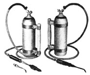
d. USE WIRE SOLDER IF A PRESTO TORCH IS USED. (SEE
ILLUSTRATION BELOW.)
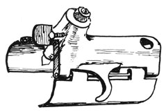
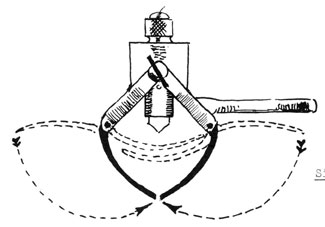
54
G. How to connect and hook up cable (continued)
Note: The lineman's outfit as shown in the above
illustration is a combination of soldering copper
and open-flame torch stem with an interchangeable
torch handle and a handle for carrying an MC Tank.
This outfit answers all requirements--soldering,
brazing, and splicing on wire, cables, transformers, switchboards, generators, and lighting
fixtures.
1) Heat splice carefully and thoroughly.
2) When the wire solder upon contact with splice will
run without the flame touching the solder, the
splice is hot enough to apply solder.
e. FEED THE SOLDER INTO THE SPLICE ON ALL SIDES.
1) Keep the flame constantly on the joint until the
splice is thoroughly saturated with solder.
f. TURN OFF TORCH AND WIPE OFF ANY EXCESS SOLDER WITH PAD
OR CLOTH WHILE STILL HOT.
g. INSPECT SOLDERING JOINT WHEN FINISHED TO RE SURE IT IS
THOROUGHLY SOLID AND TIGHT.
Note: The full size of wire must always be maintained.
Never remove any strands of the wire to accommodate
a connector or lug. If necessary, get a larger
connector or lug to fit the full size of the
cable used.
If a plumber's furnace is used, heat bar solder
in pot. Splice is prepared as above and flux
applied. Two ladles are used. The solder is
55
G. How to connect and hook up cable (continued)
poured over the splice from one ladle and the
other ladle held below to catch solder. The
solder must be poured over splice several times to
insure thorough heating of the wire. Determine by
observation when the splice is thoroughly impregnated with solder and wipe off excess solder while
still hot. Inspect work carefully.
Solder-type lugs (see illustration) should be of
proper size to accommodate the full size of the
cable to be used. Cable should be skinned so that
it will fit into the lug recess as deeply as
possible; it also should be thoroughly cleaned and
scraped.
h. HOLD LUGS FIRMLY IN A VERTICAL POSITION.
1) Apply a small amount of flux in recess of lug and
apply flux to bare wire.
i. APPLY HEAT FROM TORCH TO SIDE OF LUG AND INSERT WIRE
SOLDER UNTIL ALMOST FULL.
1) Put bare wire into recess of lug, while keeping
lug hot.
2) Keep heat on lug for several seconds.
j. REMOVE WIRE TO SEE IF IT IS THOROUGHLY TINNED AND
SATURATED WITH SOLDER.
1) When it has reached this state, apply heat again to
lug and add more solder to fill recess of lug.
2) Insert tinned wire and keep flame on lug until all
solder visible is in a liquid state.
k. REMOVE FLAME AND WIPE ANY EXCESS SOLDER AWAY IMMEDIATELY.
56
G. How to connect and hook up cable (continued)
1. HOLD BOTH LUG AND WIRE FIRMLY UNTIL SOLDER COOLS.
1) Any movement of wire or lug during the cooling
period will result in a poor electrical connection.
Note: The cooling can be speeded up by the application of a wet cloth or brush.
Solderless lugs and connectors of many types
(see accompanying illustration) are now in
general use, and the same care in preparing
and cleaning the wire is necessary. The
full size of the wire must be maintained;
the nuts, set screws, and Allen screws must
be tightened as much as possible to insure
a good electrical connection.
A loose or poor electrical connection may
be caused by a poor soldering job, dirty or
greasy wire, or solderless lugs or connectors
which are not properly fitted or tightened.
This usually results in a high-resistance
joint or in a partial or an intermittent open
circuit, both of which are sometimes very
difficult to locate. The importance of clean
wire, proper soldering, and the making of
tight connections, therefore, cannot be treated
lightly.
Connecting the lug to the terminal is usually
done with a nut or locknut.
Caution: Terminal studs and nuts should be
checked and made tight before
attaching lugs as they sometimes
work loose in shipping.
After making sure that whole assembly is
tight, lug may be attached to terminal and
terminal nuts tightened.
57
G. How to connect and hook up cable (continued)
Solderless Lugs
H. How to weld a pad
1. Supplies, tools, and equipment
A supply of pads of the proper size
Screw driver
Pliers
Hammer
Rod 2' long, with screw (of same thread as the pad) welded
on one end
Goggles (dark glass)
Gloves
Leather sleeves
2. Procedure
a. OBTAIN PADS FROM THE ELECTRIC SHOP.
1) Ask your leaderman to tell you the size of the pads
to be used.
2) Estimate the number of pads needed by counting the
places on the job which are marked in white chalk.
These marks are usually made by a dot, or by an x
with a circle.
3) Obtain requisition from your leaderman to secure
the pads from the electrical supply shop.
b. DETERMINE WHERE TO PUT THE PADS.
58
H. How to weld a pad (continued)
1) Check over job to be done. All installations are
laid out ahead of time by a layout man, and white
chalk marks will show the location of all pads to
be welded.
c. HAVE WELDING FOREMAN FURNISH A TACKER.
1) Ask your leaderman what procedure to follow in
securing a welder. He will usually take care of
this himself; if not, he will advise you where to
get one.
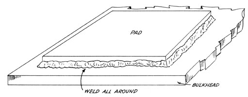
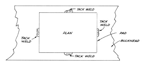
d. EXPLAIN TO WELDER HOW THE PAD IS TO BE WELDED.
1) To assure a level surface tack-weld the pad on
all four sides before welding.
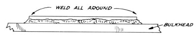
2) The weld should extend all around the pad.
Note: The top of the bead should be below the
surface of the pad in order that this
surface be left smooth. Should the bead extend
above the surface of the pad, the cable will
not strap in place as it should and the projecting bead is likely to damage the cable.
(See following illustrations.)
Perspective View of a Correctly Welded
Pad on the Bulkhead of a Ship
59
H. How to weld a pad (continued)
End View of a Correctly Welded
Pad on the Bulkhead of a Ship
Side View of a Correctly Welded
Pad on the Bulkhead of a Ship
e. ASSIST WELDER BY HOLDING THE PAD IN PLACE WHILE HE
TACKS THE PAD TO THE METAL OF THE SHIP.
1) Assist the welder in order to promote speed and to
insure that pads are welded on straight. The welder
is unable to see the pad after he pulls his hood
down over his face.
f. WATCH WELDING CAREFULLY TO SEE THAT ALL PADS ARE WELDED
ON STRAIGHT AND THAT NO WELD IS ALLOWED TO GET INTO THE
THREADS OF THE PAD.
60
H. How to weld a pad (continued)
1) Make sure the pads are straight; if they are not
straight, cable will not fit properly.
2) Keep threads in the pad free from weld; otherwise
screw will not fit.
3) If pad is damaged while welding, have the chipper
chip the damaged pad off and weld a new pad in its
place.
g. HAVE WELDER HIT EACH PAD HE WELDS WITH HIS HAMMER.
1) Do this to make sure that the weld is a good one
and that the pad will not come off when the cable
is strapped on.
h. SEE THAT ALL PADS ARE WELDED ON IN A STRAIGHT LINE.
1) Strive to have all installations done as neatly as
possible.
I. How to secure a power panel to foundation
1. Supplies, tools, and equipment
2 wrenches
Rule
Level
Declevity board
6 bolts (size per blueprint)
6 nuts (size per blueprint)
6 lockwashers (size per blueprint)
Power panel
2. Procedure
a. SECURE BLUEPRINT AND PANT, TO BE MOUNTED.
1) Secure blueprint from shop's print man.
2) Secure panel from electrical storekeeper.
a) Panel is used to safely tap the feeder.
b) Branches are connected to one side of circuit
breakers and feeder to the other side.
c) Panel is needed to safely feed branch circuits
and protect other circuits if trouble develops
in one.
b. CHECK THE PANEL MOUNTING STRAPS, FOUNDATION, AND PRINT
FOR MOUNTING HOTRS.
61
I. How to secure a power panel to foundation (continued)
1) Measure distance between holes on panel and foundation to see if they are equal. Compare these dimensions with note on print. They should all agree.
2) Use this method because it is both rapid and workable.
c. OBTAIN WRENCHES AND MOUNTING BOLTS, NUTS, AND WASHERS.
1) Obtain wrenches from tool room.
2) Obtain mounting bolts, nuts and washers on order
from warehouse.
3) Determine size of bolts, nuts and lockwashers from
blueprint.
d. MOUNT PANEL AND PLACE BOLTS IN TOP HOLES.
1) Place panel against foundation in such a manner
that bolts slip through top holes of panel and
foundation.
2) Place lockwashers and nuts on these top bolts so
panel will not tip or fall.
e. PLACE LOCKWASHERS AND NUTS ON ALL BOLTS.
1) Use lockwashers to lock nuts on bolts.
2) Place lockwashers on bolt after bolt has passed
through panel strap holes and foundation holes.
f. TRUE UP PANEL AND TIGHTEN BOLTS.
1) Use declevity board and level to true up or
straighten panel on foundation.
2) Do not tighten up all the way on one bolt first.
Make a few turns on each bolt until all are firm
and tight.
g. CHECK PANEL POSITION WITH PRINT.
1) Take rule and measure all points that are detailed
in print.
h. RETURN TOOLS TO SHOP AND PRINT TO RACK.
1) Return tools to tool room and receive signed slip
from tool keeper.
2) Return prints to shop's print man and receive slip
you signed.
62
I. How to secure a power panel to foundation (continued)
3) Keep close watch on signed slips as they are
important.
i. REPORT COMPLETED PANEL JOB TO FOREMAN.
1) The job is not finished until your report is made.
The foreman will determine in advance at what stage
of the job a report is to be submitted. When this
point is reached, a written or verbal report should
be made immediately to the foreman or his assistant.
J. How to put a strap on a cable (drill and tap)
1. Supplies, tools, and equipment
Hammer
Center punch
Air drill, or electric drill
13/64" taper shank drill bit or straight shank drill
bit
1/4" - 20 starting tap
1/4" - 20 finishing tap
A small amount of grease or oil
A single hole cable strap to fit cables
1/4" - 20 R. H. brass screws
Screw driver (about 8")
Soapstone
2. Procedure
a. OBTAIN THE TOOLS AND MATERIAL.
1) Obtain the drill, bit, and tap from the tool room.
2) Secure the other tools from your own tool box.
3) Secure the necessary screws and straps either from
a supply available on the job or by order from the
electrical supplies storeroom.
b. LOCATE THE STRAP.
Note: It is assumed that the cable run is already laid
out and that layout is a separate job.
1) Locate the first strap either 8 inches from the
first tube or lightening hole, or 18 inches from
the last preceding strap, as the case may be.
2) Place the strap so that it will line the cable up
properly and mark with pencil the center of the
screw holes.
63
J. How to put a strap on a cable (drill and tap) (continued)
c. CENTER PUNCH THE HOLE.
1) Set the center punch with the point on the mark just
made so that it stands squarely with the plate.
2) Strike it a light blow and check to be sure the
punch has not slipped. If correct, re-insert the
center punch in the punch mark and strike it a hard
blow, leaving a full-sized punch mark.
d. DRILL THE HOLE.
1) A 13/64" drill is the proper tap size for a
1/4" - 20 brass screw in steel plate. A 7/32"
drill may be used in some cases but usually it will
make a loose fit and inferior job.
2) Drill the hole clear through the plate, but before
doing so be certain that there is nothing on the
other side of the plate that you might damage by
drilling here.
e. TAP THE HOLE.
1) Tap the hole first with the starting tap and next
with the finishing tap.
2) Use plenty of oil or grease.
3) The job may be done in soft steel in one operation
only with the finish tap if you are skillful enough,
but it is best to do the job in two stages.
Note: Be very careful in this operation as there is
great danger of breaking the tap if too much
pressure is applied, or if the twist on the
wrench is uneven. Usually a broken tap cannot be removed from the hole; however, if tap
is broken, care should be taken to see that
there are no small pieces of hard steel left
in the hole since these would cause another
tap to break when job is being completed.
f. PLACE CABLE IN POSITION.
1) Bring the cable into its proper position; while
holding it up by hand straighten it out so it will
remain in the proper position.
g. PLACE STRAP ON CABLE.
1) Place screws and screw driver within easy reach.
2) Place the strap on the cable in its proper place
with one hand.
64
J. How to put a strap on a cable (drill and tap) (continued)
3) Secure screws and screw driver with the other hand.
h. INSERT SCREW IN STRAP AND SCREW UP.
1) Insert a 1/4" - 20 round head brass screw in the
strap and start it in the tapped hole.
2) Be careful not to start it cross threaded.
3) Screw it up tight enough to hold the weight of the
cable.
i. STRAIGHTEN THE CABLE.
1) Pull the cable up by hand.
2) Tap it with the hammer handle to take out humps.
3) Be careful that you do not damage the cable.
j. STRIKE THE STRAP WITH HAMMER TO TAKE UP SLACK.
1) Tighten up the screw and then hit the strap hard
enough to set it firmly against the plate, being
careful that you do not distort it or damage the
cable.
k. TIGHTEN UP THE STRAP.
1) Tapping the strap should enable you to take up the
screw a little more.
2) Do not twist off the head of the screw.
l. INSPECT THE JOB.
1) Check the job and correct any faults in alignment
and workmanship which may be discovered.
3. Questions
a. How could you put a strap on a cable without drilling
and tapping a plate?
b. What method do you think would be most suitable on an
aluminum bulkhead?
c. Would you expect a screw in a tapped hole to be watertight?
d. Why wouldn't you run a cable along the deck--or would
you?
e. Suppose that you had so much cable to strap up that you
had 50 holes to drill and tap. Can you think of a way
to make the job easier?
65
K. How to install cable in a battery compartment
1. Objectives
a. To properly install batteries in the battery room or
box.
b. To properly install and protect from acid, wiring and
fittings in battery room or box.
2. Introductory information
Batteries on board ship must be ready for service at all
times as they are used for starting and running emergency
equipment, general alarm bells, telephones, etc. Only lead
cable should be used in battery compartments.
Open flame should never be used around batteries or in a
battery compartment. Care must be taken not to drop or tip
batteries. They should remain on the charging line as long
as practical and should be installed just before the final
tests.
3. Supplies, tools, and equipment
Pocket tools
Electric drill
Drills and taps of appropriate size
Hammer
Center punch
Rubber tape
Insulating varnish or Glyptal
Packing and Hydroseal
Vaseline
4. Procedure
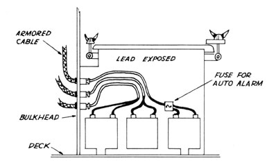
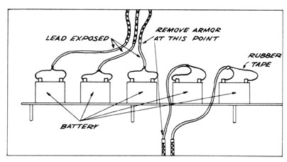
a. REMOVE THE OUTER STEEL OR BRONZE ARMOR FROM THE POINT
WHERE THE BATTERY LEADS ENTER THE BOX.
1) Never leave any metal other than lead on the cables.
2) When a battery compartment is used, the armor is removed to a point well out of reach of the acid mist
which the battery gives off during the charging period
(about 4' above the battery shelf, or from the point
where they leave the kickpipe if it is under the shelf).
b. REMOVE THE TAPE PROTECTION UNDER THE ARMOR, THUS EXPOSING THE LEAD.
1) Handle with care cable that has the armor and tape
removed, as the lead breaks very easily.
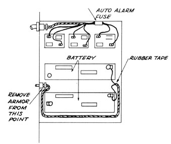
c. STRAP THE CABLE VERY SECURELY TO THE POINT WHERE THE
LEAD IS TO BE REMOVED FOR HOOKING UP.
1) Remove the lead about 18 inches from the end.
d. SOLDER ON BATTERY TERMINALS.
66
K. How to install cable in a battery compartment (continued)
e. COVER THE EXPOSED WIRES FROM TERMINAL TO A POINT AT
LEAST 2 INCHES OVER THE LEAD.
1) Cover with a double layer of rubber tape.
2) Be sure no wire is exposed.
f. PAINT THE CABLE FROM THE POINT OF ENTRY TO THE BATTERY
TERMINAL.
1) Paint with two coats of insulating varnish.
2) Cover the terminals with vaseline.
5. Illustrations
a. Battery installations
Section of Battery Box
67
K. How to install cable in a battery compartment (continued)
Cable with Armor and Tape
Removed (Top View)
Battery Box Note: Mark all terminals so they may be identified easily
(+ on white wire and - on black wire).