The student must rely to some extent upon his mechanical
ability to direct him in the proper use of tools. Only a few
of the more important points in the care and use of tools are
covered here.
The tools listed below are the minimum essentials which every
helper should have before going out on a job.
B. Supplies, tools, and equipment
7" or 8" pliers (lineman or side cutter)
7" diagonal pliers
Channel lock pliers (pump pliers)
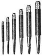
3" insulated screw driver
6" insulated screw driver
8" insulated screw driver
6" crescent wrenches
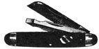
Heavy pocket knife
Linoleum knife
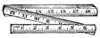
6' zig-zag, or other wooden rule
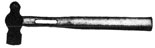
Ball peen hammer
Center punch
C. Care and use of tools
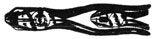
1. PLIERS (side-cutter type usually known as lineman's pliers)
a. These pliers are used for cutting wire and making up
joints.
b. The proper cutting procedure is to give the pliers a
slight downward twist as the pressure is applied to
the handles.
c. The joint of the pliers should be oiled occasionally.
Pliers should not be used to hold anything that is hot
or is being heated, as heat takes the temper out of the
pliers.
1
C. Care and use of tools (continued)
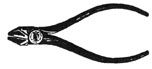
2. DIAGONAL PLIERS
a. Diagonal pliers are used for cutting and skinning wire.
b. Their handling and care is the same as that for lineman
pliers.
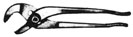
3. CHANNEL LOCK PLIERS (pump pliers)
a. Channel lock pliers are a special make of pump pliers
that are used extensively by marine electricians because they are strong and safe. They are not as likely
to slip as are other makes of adjustable pliers.
b. These pliers are used to install kickpipes and to
tighten bushings and locknuts. They are also used
wherever quickly adjustable pliers are needed.
c. Channel lock pliers require very little care except
for an occasional cleaning of the gripping teeth.
4. INSULATED SCREW DRIVERS
a. Screw drivers are insulated to protect the user from
electric shock.
b. They are used to drive, and to tighten or loosen screws.
They must not be used as chisels or pry bars.
c. A screw driver is one of the most dangerous tools in the
kit; it should be handled with great care. A slip in
handling often means a punctured skin or the loss of an
eye. Never carry a screw driver in your pocket with the
handle down. Always keep the point protected.
2
C. Care and use of tools (continued)
d. A screw driver should never be ground unless it is done
by an expert. Incorrect grinding causes the screw
driver to slip easily.
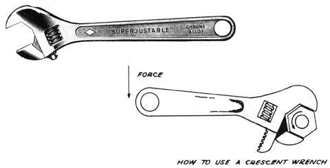
5. CRESCENT WRENCHES
a. Crescent wrenches are well-known, adjustable wrenches
that have a wide use in the electrical field. They are
used whenever a bolt can be easily reached.
b. When using a crescent wrench, one should make sure that
the adjustable jaws are always on the side opposite the
applied force. The wrench is so constructed as to form
a brace against spreading of the jaws when used properly.
6. POCKET KNIFE OR LINOLEUM KNIFE
a. Knives are used to skin and scrape wires, to cut cable,
and to cut, scrape or trim any soft metal or wood.
b. Knives should be kept sharp at all times. A fine-grit
power emery stone, which is kept cool by frequently
dipping it in cool water, can be used for this purpose.
The knife should be ground slowly, as fast grinding
may cause it to burn. A whetstone can be used to touch
up the knife occasionally.
c. Do not use a knife in any way that may cause injury to
yourself or others. Never try to split a round object,
such as a cable, by holding the left hand under the
knife while splitting, as a slip of the knife might
cause serious injury.
3
C. Care and use of tools (continued)
7. SIX-FOOT RULE
a. A wooden zig-zag rule is selected because it is light
and will not conduct electricity.
b. One should not attempt to estimate distances by
"guess work"; the use of a rule for measuring is a
necessary precaution against inaccuracy.
c. The rule should be oiled at the joints to permit easy
working and to prevent wear. It should be kept
absolutely clean; any paint or dirt spots which may
get on it should be removed immediately.
8. BALL PEEN HAMMER
a. A ball peen hammer should be carried at all times and
used wherever a hammer is needed.
b. The peen may be covered with rubber and friction tape
to make a soft mallet for dressing and pounding cable.
4
C. Care and use of tools (continued)
9. CENTER PUNCH
a. A center punch is used to center holes for drilling.
After the position of the hole is determined with the
rule, the center punch is placed on the mark and struck
with a hammer. This mark shows where the drill should
be started.
b. The center punch should be kept sharp and should be
ground always at the same angle as when new.
5
II. CABLE HANGERS
A. How to make cable hangers and lugs
1. Objective
To show the proper method of manufacturing hangers and
lugs used for the support of cables throughout the ship.
2. Introductory information
Cable hangers and lugs are used to support cable runs
throughout the ship wherever it is necessary to keep the
cables away from the deck or bulkhead. The "cable rack"
is the complete installation and consists of hanging lugs,
hanger, and strap. The success of the installation job
depends upon the correct making of these parts, which requires accuracy in measuring and bending, as well as the
proper use of tools.
3. Supplies, tools, and equipment
Center punch
1-lb. ball peen hammer
Heavy-duty shear or power hacksaw
6' rule
Bending machine
Punch (size for punching 1/4" or 3/8" iron)
Strap iron (1-1/4" x 1/4" x 3/8"--as specified in blueprint)
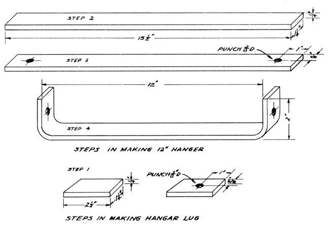
4. Procedure
a. MAKING THE LUG
1) Square and shear off one end of strap iron (material
as specified).
2) Measure to length as specified (in this case
2-1/2 inches).
3) Shear off square. This gives us a flat iron bar
1-1/4" x 1/4" x 2-1/2". Two of these bars are needed
for each hanger.
4) Put a center punch mark 1 inch from the end of each
of these bars, being sure that it is in the center
of the material.
5) Drill or punch a 3/8-inch hole at the center punch
mark for the bolt. This completes the lug. Two
lugs are needed for each hanger. (See accompanying illustration.)
6
A. How to make cable hangers and lugs (continued)
b. MAKING THE HANGER
1) Select the proper size of iron bar (as specified).
2) Square and shear off one end of iron bar.
3) Measure off the proper length for a 12-inch
hanger (as specified). Allow for a 2-inch lip at
each end to be bent at right angles. Since inside
measurements are given, allowance must be made for
thickness of material; therefore 1/2 inch is
subtracted from total length. The total length is
now 15-1/2 inches.
4) Shear off at this mark. (See illustration,
Step 2.)
5) Measure 1 inch from each end and center punch in
center of material.
6) Punch a 3/8-inch hole at each center punch mark.
(See Step 3 of accompanying illustration.)
7) Since outside dimensions are given for the 2-inch
lip, the flat bar is placed in the bender 1-3/4 inches
from the end, and a 2-inch lip is bent at right
angles on each end. (See illustration, Step 4.)
8) The hanger is next galvanized or zinc coated. Red
lead paint is used when specified. Lugs do not
need this coating as they are welded to the ship's
structure.
7
A. How to make cable hangers and lugs (continued)
5. Illustrations
8
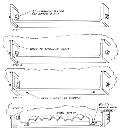
B. How to install cable hangers
1. Objective
To show proper method of aligning and installing hanging
lugs for the support of cable hangers.
2. Introductory information
All cables on shipboard are supported in cable racks built
of a series of hangers and lugs, placed at regular intervals
(as specified by the builders), and perfectly aligned. The
cables are then secured to the hangers by suitable types of
straps. The straps are secured in place by machine screws
for which the hanger must be drilled and tapped. (See
accompanying illustration, Steps 3 and 4.)
3. Supplies, tools, and equipment
6' rule
Channel lock pliers
Heavy gauntlet-type gloves
Chalk line
Ladder
Marking crayon
6" crescent wrench
Necessary number of lugs and hangers (hangers to be of
the proper size to accommodate the number and size of
cables to be in run)
4. Procedure
a. SECURE THE RIGHT NUMBER OF LUGS AND HANGERS OF THE
PROPER WIDTH TO ACCOMMODATE THE CABLES TO BE RUN.
(SEE ILLUSTRATION.)
1) Bolt a hanging lug to each lip of hanger. (See
illustration, Step 1.)
2) Determine center line for the run of cable.
3) Put a mark at each end of the run over to one side
of the center line, a distance of half the width
of the hanger.
4) Run a chalk line between these two marks and line
one side of the hanger to this line.
5) Mark off the distance between hangers as shown in
the illustration.
b. WELDING THE LUGS
1) When the electric welder is ready to weld the lugs
to the deck or bulkheads, the helper will hold the
strap square with the line of run, and one lug on
9
B. How to install cable hangers (continued)
the aligning mark while it is being welded in
place. (See illustration, Step 2.)
Note: Wear heavy duty, gauntlet-type gloves to
protect the hands and arms from welding
sparks. Leave no part of the arms exposed
to the arc. Use welding helmet to protect
face and eyes. Never look directly at an
electric arc unless properly fitted with
dark glasses.
Installation of Hanger
10
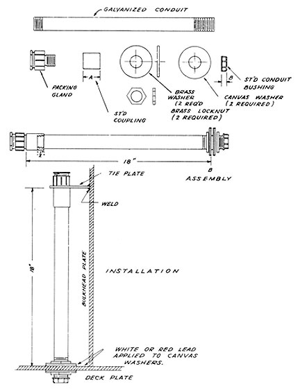
III. MAKING KICKPIPES
A. How to make a Type A kickpipe
1. Introductory information
Cables which are run through decks are insured against
mechanical injury by kickpipes. The installation of these
cables is made watertight by the use of washers, locknuts,
and red lead around the pipe where it goes through the deck
or is welded to the deck. A properly packed terminal tube
keeps the water from going through the pipe. The installation and packing of the tube will be given in another
lesson. (See accompanying illustration.)
2. Supplies, tools, and equipment
Hacksaw
Reamer
Rule
Stock and dies
Pipe wrenches
Pipe vise
Cutting oil
Conduit bushing
Conduit of proper size to
accommodate cable to be
run through it
Conduit coupling
Terminal tube
2 brass locknuts
2 canvas washers
3. Procedure
a. PUT A LENGTH OF CONDUIT IN VISE.
1) Thread 1/2 inch or more, according to size of conduit.
2) Ream it.
b. SCREW ON A CONDUIT COUPLING.
1) Tighten with pipe wrench.
c. MEASURE OFF AND MARK THE CONDUIT 18 INCHES FROM THE TOP
OF COUPLING. (THIS WILL BE THE TOP OF THE THREADS WHEN
THEY ARE CUT ON THE CONDUIT.)
d. MEASURE THE DISTANCE THROUGH THE DECK.
1) Add the space taken up by the locknuts, washers,
and bushing.
2) Add 1/2 inch.
e. ADD THE ABOVE TOTAL DISTANCE TO THE 18-INCH MARK.
1) Cut off the conduit with a hacksaw.
11
A. How to make a Type A kickpipe (continued)
f. THREAD A STRAIGHT THREAD (NOT TAPERED) TO THE 18-INCH
MARK.
1) Ream the end.
g. SCREW ON A LOCKNUT.
1) Put on a brass washer, two canvas washers, another
brass washer, another locknut, and the bushing.
h. SCREW A TERMINAL TUBE INTO THE COUPLING. (IT NEED NOT
BE TIGHTENED AS IT WILL HAVE TO COME OUT AGAIN WHEN THE
PIPE IS INSTALLED.)
i. THE KICKPIPE IS NOW COMPLETED AND READY FOR INSTALLATION.
4. Illustrations
Type A Kickpipe
(Parts)
12
B. How to install Type A kickpipe
1. Introductory information
All kickpipes in any one grouping, regardless of their size,
must be the same height above the deck to insure a good
looking job. It will be assumed that two or more kickpipes
are going in this location and that the holes are already
laid out and drilled through the deck. The pipes are held
securely at the top by tie plates which are already on hand.
The tie plates are to be welded to the bulkhead after the
pipes are installed. (See illustration.)
2. Supplies, tools, and equipment
Completed kickpipes of proper size
Tie plates
Pipe wrench
Lock channel pliers
3. Procedure
a. DETERMINE THE PROPER SIZE OF KICKPIPE FOR THE FIRST
HOLE ON EITHER END.
b. TAKE OFF THE BUSHING, FIRST LOCKNUT, BRASS WASHER, AND
CANVAS WASHER.
c. PUT A GOOD COATING OF RED OR WHITE LEAD AROUND TEE HOLE.
d. INSERT THE THREADED END OF THE KICKPIPE THROUGH THE
HOLE WITH TEE CANVAS WASHER AGAINST THE DECK.
1) Put a coating of red or white lead on the under
side of the deck around the hole.
2) Put the canvas washer over the pipe against the
deck.
3) Put on the brass washer and then the locknut.
Screw tight with wrench.
4) Put on the bushing and screw tight with channel
lock pliers.
e. (ABOVE DECK) TAKE OFF THE TERMINAL TUBE AND INSERT IT
THROUGH THE PROPER TIE PLATE.
f. SCREW THE TERMINAL TUBE (WITH TIE PLATE) INTO THE
COUPLING AGAIN AND TIGHTEN WELL WITH PIPE WRENCH.
Note: The tie plate will be welded on to the bulkhead
later.
g. PUT THE NEXT KICKPIPE INTO THE ADJACENT HOLE IN THE
SAME MANNER.
13
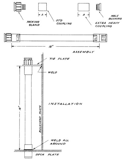
C. How to make a Type B kickpipe
1. Introductory information
On a Type B kickpipe, an extra-heavy coupling is screwed
onto the lower end of the pipe. This coupling goes through
the deck and is welded in place. Otherwise the procedure
is the same as for making a Type A kickpipe. Measurements,
however, are different. Regardless of type, they both
measure 18 inches from the deck to the top of the top
coupling.
2. Supplies, tools, and equipment
Hacksaw
Reamer
Rule
Stock and dies
Pipe wrenches
Pipe vise
Cutting oil
Proper size conduit to accommodate the cable to be run
through it
Regular conduit coupling
Extra-heavy conduit coupling
Bushing
3. Procedure
a. PUT A LENGTH OF CONDUIT IN THE PIPE VISE.
1) Thread one end.
2) Ream this end with a pipe reamer.
b. SCREW ON A CONDUIT COUPLING.
1) Tighten it with a pipe wrench.
c. TO DETERMINE THE POINT AT WHICH TO CUT OFF THE CONDUIT,
PROCEED AS FOLLOWS:
1) Measure off on the conduit 18 inches from the top
of the coupling.
2) Hold an extra-heavy coupling alongside the conduit
with its center at the 18-inch mark.
3) Estimate the distance the conduit will screw into
the coupling, and mark the conduit for cutting at
this point.
d. CUT OFF THE CONDUIT WITH A HACKSAW AT THIS LAST NARK.
e. THREAD THIS END OF THE CONDUIT.
1) Ream it with a pipe reamer.
14
C. How to make a Type B kickpipe (continued)
f. SCREW ON THE EXTRA-HEAVY COUPLING AND TIGHTEN IT WITH
A PIPE WRENCH.
g. SCREW A BUSHING INTO THE OPEN END OF COUPLING.
h. THE TYPE B KICKPIPE IS READY FOR INSTALLATION.
4. Illustrations
Type B Kickpipe
(Parts)
15
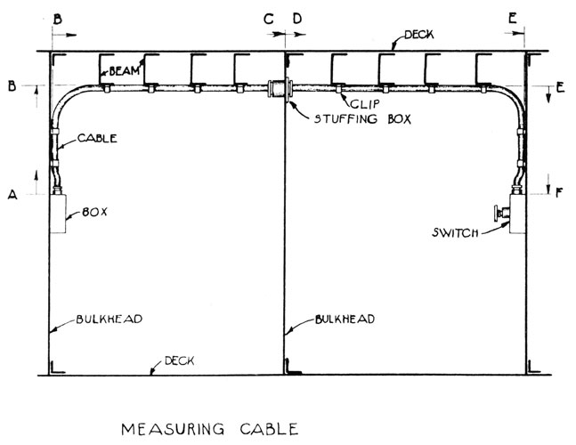
IV. HOW TO MEASURE CABLE RUN
A. Introductory information
After the cable run has been determined from the blueprints, it
is generally spotted in, chalked in, or painted in on the ship's
structure. It is then necessary for the electrician or his
helper to measure the length of the run in order that the cable
may be cut the correct length before pulling in. It must be
measured from its start to its finish with all due allowances
made for offsets and for racking. (See accompanying illustration.)
B. Supplies, tools, and equipment
6' zig-zag rule
pencil
Paper
C. Procedure
1. DETERMINE THE LOCATION OF THE TWO ENDS OF THE RUN FROM THE
BLUEPRINT.
2. FIND THE LOCATION OF THE CABLE RUN WHERE IT HAS BEEN SPOTTED
IN BY THE LAYOUT MAN.
3. START AT ONE END AND ALLOW FOR MAKING UP IN JUNCTION BOX,
OUTLET BOX, OR OTHER TERMINAL BOX. (SEE ILLUSTRATION, A.)
a. This measurement is based on an estimate gained by
experience. The beginner should ask the electrician
the allowance to make.
4. MEASURE THE FIRST STRAIGHT RUN. (SEE ILLUSTRATION, B.)
a. Do not take off for cable cutting across bends.
b. Make all measurements as though they were at right
angles.
5. MEASURE ALL STRAIGHT RUNS (A TO B, B TO C, D TO E, AND
E TO F) IN THE SAME WAY. (SEE ILLUSTRATION.)
6. MAKE ALLOWANCE FOR MAKEUP IN TERMINAL BOX AS IN PROCEDURE
NO. 3.
7. ADD TOGETHER ALL MEASUREMENTS TAKEN.
a. If the run is a long one, it is advisable to add 5 feet
for every 100 feet of run. (Add 2-1/2 feet for 50 feet
of run, etc.)