(a) General Discussion.-The DD445 class generating plant consists of two turbine-driven ship's service generating units, located one in each engine room, and one Diesel-driven emergency generator located in the Diesel generator room forward on the starboard side). Each unit has its own switchboard for control of the generator and for distribution of power to the ship's service and emergency power systems.
(b) Ship's Service Units.-Power for the ship's service system is supplied by two 290 kw, turbine-driven generating sets which consist of the following component parts
1. Turbine and reduction gear. (See sec. IX.)
2. AC generator.-250 kw. 450 volts, 0.80 power factor, 3-phase, 60-cycle, 400-ampere. separately excited with a revolving field.
3. DC generator.-40 kw, 120 volts, 333 amperes, stabilized shunt field. This DC generator provides excitation for the above AC generator, in addition to supplying the 120 volt DC power system.
All necessary provisions for controlling the generating sets and for the distribution of power have been incorporated in their respective switchboards. The forward ship's service generator and distribution switchboard is designated as the control switchboard and as such is provided with instruments and controls for the after generator to allow for paralleling and dividing the load from the forward ship's service switchboard. Normally all paralleling of the generators is done from the forward ship's service switchboard. Since the AC generator voltage is dependent upon the degree of field excitation, a voltage regulator is mounted on each switchboard, which operates automatically to vary the field excitation in order to maintain constant voltage throughout normal changes in load. To do this the voltage regulator operates a field rheostat motor which in turn operates the generator field rheostat to vary the degree of excitation. A stand-by regulator and a transfer switch are also located on each switchboard to provide for automatic regulation in case the regulator in operation should fail. In case of the failure of both regulators,
the field rheostat motor may be operated by a manual control switch on the switchboard and in case of the failure of the field rheostat motor, the rheostat may be operated directly by a manual control located on the switchboard. The voltage of the DC generator does not require automatic regulation and is, therefore, controlled only by a manually operated field rheostat.
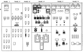
(c) Ship's Service Generator and Distribution Switchboards.-Figures 70 and 71 are line illustrations of the forward and after ship's service generator and distribution switchboard, as indicated, is divided into six panels.
Panel I.-AC lighting and power distribution.
Panel II.-AC battle and general power distribution.
Panel III.-Restricted battle power distribution.
Panel IV.-AC generator control panel.
Panel V.-(Forward Switchboard) After generator control and AC and DC bus ties. (After board) Emergency switchboard and shore connection feeders and AC and DC bus ties.
Panel VI.-DC generator controls and distribution of DC power.
Instruments and switches which are shaded in the illustrations are numbered and the key to these numbers appears on the illustration. It will be noted that the instruments and switches providing the same service on each board have the same number. These numbers are used to key the operating instructions later outlined.
(d) Emergency Service Units.-To provide electrical power to certain vital auxiliaries and to provide a limited amount of lighting in the case of failure of the ship's service power, an emergency Diesel generating unit is provided. It consists of the following component parts:
1. Diesel engine. (See sec. X.)
2. AC generator.-100 kw., 450 volts, 0.60 or 0.80 power factor, 3-phase, 60-cycle, 214 amperes.
3. Exciter.-Direct-connected DC generator. 120 volts. shunt-wound.
149
PANEL I A.C. LIGHTING AND POWER
PANEL II A.C. BATTLE AND GENERAL POWER
PANEL III RESTRICTED BATTLE POWER
PANEL IV A.C. GENERATOR CONTROL
PANEL V A.C. AND D.C. BUS TIES, EMERGENCY SWITCHBOARD AND SHORE CONNECTION FEEDERS
PANEL VI D.C. GENERATOR CONTROL
A2 A.C. Generator Circuit Breaker
B2 D.C. Generator Circuit Breaker
C2 D.C. Bus Tie Circuit Breaker
D2 A.C. Bus Tie Circuit Breaker
E2 A.C. Lighting Circuit Breaker
F2 A.C. Battle and General Power Circuit Breaker
G2 Emergency Generator Bus Circuit Breaker
H2 Shore Power Switch Circuit Breaker
1. VOLTMETER, #2 A.C GENERATOR
1a. VOLTMETER SWITCH
2. AMMETER
2a. AMMETER SWITCH
3. FREQUENCY METER, #2 A .C GENERATOR AND BUS
3a. FREQUENCY METER SWITCH
4. SYNCNROSCOPE
4a. SYNCHROSCOPE SWITCH
5. SYNCHRONIZING LAMPS
5a. SYNCHRONIZING LAMP SWITCH
6. A.C. VOLTAGE CONTROL (MOTOR OPEPATED)
7. A.C. VOLTAGE CONTROL RHEOSTAT (MANUAL)
8. VOLTAGE REGULATOR CUT OUT SWITCH
9. GOVERNOR MOTOR TRANSFER SWITCH
10. GOVERNOR MOTOR CONTROL SWITCH
11. FIELD CUT OUT SWITCH, #2 A.C. GENERATOR
12. D.C. VOLTMETER
13. D.C AMMETER
14. D.C. VOLTAGE CONTROL RHEOSTAT
22. INDICATING LAMP A.C. BUS TIE
23. INDICATING LAMP D.C. BUS TIE
AFTER GENERATOR AND DISTRIBUTION SWITCHBOARD
DD 445 CLASS
FIG. 71
150
This Diesel generating unit starts up automatically on failure of the ship's service power system. This occurs within 10 seconds after failure of the ship's service system.
DD445 class ship's emergency power system is arranged to provide automatic transfer of the circuits for the I. C. switchboard and steering power panel. DD692 class ships are arranged for automatic transfer of the steering power panel only.
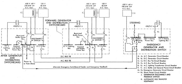
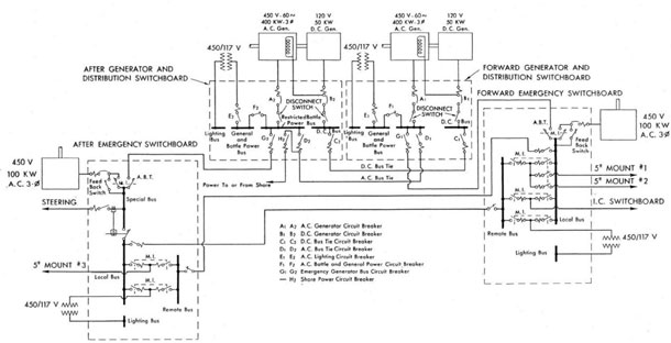
(e) Interconnections.-Figure 72 shows in single line schematic form the connections between these three generating units and their respective switchboards and the interconnections between the three switchboards. It will be noted that the AC and DC buses on the forward and after ship's service generator and distribution switchboards can ha connected together. This enables one unit to supply power to both ship's service switchboards when the other unit is out of service and also provides a means for parallel operation of the two generating sets. However, under split plant conditions the generators are operated separately, each unit providing power for its own section of the ship. The emergency generator and distribution switchboard is normally energized by the forward ship's service switchboard. Should the voltage at the forward board fall below 350 volts, the feed to the emergency board will automatically transfer to the after ship's service switchboard if the voltage there remains above 405 volts. If neither the forward nor the after ship's service switchboards are energized, the emergency Diesel generator will start automatically and take over the emergency load. When the ship's service power is restored and the voltage on either of the ship's service switchboards rises to 405 volts or above, the emergency load is automatically removed from the Diesel generator and the emergency switchboard again energized from the ship's service board. The Diesel generator is then operating without load. The Diesel engine will not stop automatically, but must be secured manually. Figure 72 shows an interconnection between the emergency generator switchboard and the after ship's service switchboard. This is a "feed-back" connection provided for use when both ship's service generators are secured and when shore or tender power is not available. Through this interconnection the emergency generator may be connected to the ship's service board and supply a limited amount of power to the ship's service system. Figure 72 shows also a connection from the after
switchboard to shore power. This connection is led to a connection box provided on deck so that the ship's service switchboards may be energized from ashore or from another ship. This connection may also be used to supply power, from the after switchboard, to the shore or to other ships alongside.
2. GENERATING PLANT DD692 CLASS
(a) General Discussion.-The arrangement of the DDGO2 class generating plant is essentially the same as that of the DD445 class. However, in order to accommodate the increased ship's service load of the ship and to provide sufficient capacity to enable one generator to carry the entire battle load if necessary, the capacity of the ship's service generators has been increased, and an additional Diesel-driven emergency generator has been provided.
(b) Ship's Service Units.-The ship's service power system is supplied by two turbine-driven generating sets consisting of the following component parts:
1. Turbine and Reduction Gear. (See sec. IX.)
2. AC Generator.-400 kw., 450 volts, 0.80 power factor, 3-phase, 60-cycle, 642 amperes with separately excited revolving field.
3. DC Generator.-50 kw., 120 volts, 417 amperes with stabilized shunt field. This DC generator provides excitation for the AC generator in addition to supplying power for the 120 volts DC power system.
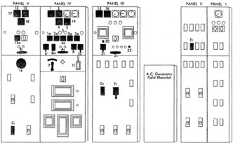
(c) Switchboards.-The switchboards for control of the generators and for distribution of power have been rearranged as shown in Figures 73 and 74 but include essentially the same generator controls and distribution system as previously described for the DD445 class switchboards. Five panels appear on these boards, designated as follows:
Panel I.-AC lighting.
Panel II.-AC battle and general power.
Panel III.-AC bus ties and restricted battle power.
Panel IV.-AC generator controls.
Panel V.-DC generator controls, bus ties, and feeders.
It will be noted that the key numbers applied to the instruments on these boards are the same as the key numbers applied on the DD445 class boards.
151
A1 A2 A.C. Generator Circuit Breaker
B1 B2 D.C. Generator Circuit Breaker
C1 C2 D.C. Bus Tie Circuit Breaker
D1 D2 A.C. Bust Tie Circuit Breaker
E1 E2 A.C. Lighting Transformer Circuit Breaker
F1 F2 A.C. Battle and General Power Circuit Breaker
G1 G2 Emergency Generator Circuit Breaker
- H2 Shore Power Circuit Breaker
J. GENERATOR DISCONNECT AND FEEDBACK SWITCH
K. AUTOMATIC BUS TRANSFER EQUIPMENT
DD 445 CLASS
GENERATOR AND DISTRIBUTION SWITCHBOARDS
FIG. 72
152
(d) Emergency Service Unit.-Because of the increased ships service and emergency load on the DD692 class, two 100-kw. Diesel emergency generating units have been provided to deliver emergency power. These units are duplicates of those in the DD445 class. One of these is located in the emergency generator room forward and the other is located in the emergency generator room aft. The forward emergency switchboard is normally energized from the forward ship's service switchboard. and the after emergency switchboard from the after ship's service switchboard.
(e) Interconnections.-Figure 75 shows in single line schematic form the connections between the generating units and their respective switch boards and the interconnections between the switchboards. As in the DD445 class. the ship's service switchboards can be connected together to allow one board to provide power for the other a well a to allow for parallel operation of both generating sets. The forward and after emergency generator and distribution switchboards are normally energized from the ship's service switchboard in its own section of the ship. If the voltage on one of the ship's service switchboards should drop to 290 volts or less. the emergency generator of that system will start automatically and provide emergency and lighting to that section of the ship in which it is located. When the ship's service voltage on the ship's service switchboard in question is reestablished, the emergency generator is automatically disconnected and its board again energized from the ship's service switchboard. As in the DD445 class, the Diesel engine must be secured manually. Under no circumstances should the emergency generators be allowed to operate in parallel, and interlocking switches are provided to prevent this. A crossconnection between the emergency switchboards is, however, provided in order to allow for the transfer of emergency power from one emergency generator to the other emergency board to service certain vital auxiliaries. When this is done it is not possible to operate the two emergency generators in parallel due to the interlocking switches.
3. OPERATION
(a) General Discussion.-The following discussion of the operation of the ship's service generating plants is provided for the benefit of engineering ratings other than electrician's mates.
It is highly desirable that engine room personnel be acquainted with the basic steps in operating ship's service switchboards in order that they may be able to accomplish these operations in the absence of an electrician's mate. As noted in section IX, paragraph 2, each machinist's mate should be capable of single-handedly warming up, cutting in, paralleling, and securing the ship's service generators and switchboards in order to qualify for engine room watches. Under all conditions a qualified electrician's mate should be called as soon as Possible to make final adjustments to the generator switchboards and plant.
(b) Operation of a Single Ship's Service Generator.-This discussion will be started with the generator and distribution switchboard having no source of power, that is, with the DC bus tie switch (C) open; the AC bus tie switch (D) open, the emergency switchboard feeder switch (G) open; and in the case of the after switchboard, the shore power switch (H) open. In this condition the engine room would have to be supplied with emergency lighting and power directly from the emergency switchboard or in case the emergency generator is not in operation, lighting only would come from the portable hand lanterns. With the board in this condition the following are the basic steps in placing a ship's service generator in service. Do not start the turbine until the generator controls have been set in the following position:
1. AC generator circuit breaker (A) in "open" position.
2. Field cut-out switch (11) in "open" position.
3. AC voltage control rheostat (manual) (7) turned to extreme "lower" position.
4. Voltage regulator cut-out switch (8) in "man" position.
5. DC generator circuit breaker (B) in "open" position.
6. DC voltage control rheostat (14) in extreme "lower" position.
With the board adjusted as above the turbine may be brought up to approximately its rated speed. Both the DC generator disconnect switch and the AC generator disconnect switch (located behind the switchboard) should now be closed. The DC voltage (12) should now be raised to 120 volts by adjustment of the DC voltage control rheostat (14). The DC circuit breaker (B) should then be closed. This will connect the DC generator to the DC bus. To place the AC
153
PANEL I A.C. LIGHTING
PANEL II A.C. BATTLE AND GENERAL POWER
PANEL III A.C. BUS TIES AND RESTRICTED BATTLE POWER
PANEL IV A.C. GENERATOR CONTROL
PANEL V D.C. GENERATOR CONTROL, BUS TIES AND FEEDERS
A1 - A.C. Generator Circuit Breaker
B1 - D.C. Generator Circuit Breaker
C1 - D.C. Bus Tie Switch
D1 - A.C. Bus Tie Switch
E1 - A.C. Lighting Switch
F1 - A.C. Battle nod General Power Switch
G1 - Emergency Generator Bus Switch
1. VOLTMETER, #1 A.C. GENERATOR
1a. VOLTMETER SWITCH
2. AMMETER, #1 A.C. GENERATOR
2a. AMMETER SWITCH
3. FREQUENCY METER #1 A.C. GENERATOR AND BUS
3a. FREQUENCY METER SWITCH AND TRANSFER SWITCH
4. SYNCHROSCOPE
4a. SYNCHROSCOPE SWITCH
5. SYNCHRONIZING LAMPS
5a. SYNCHRONIZING LAMP SWITCH
6. A.C. VOLTAGE CONTROL (MOTOR OPERATED)
7. A.C. VOLTAGE CONTROL RHEOSTAT (MANUAL)
8. VOLTAGE REGULATOR CUTOUT SWITCH
8a. VOLTAGE REGULATOR BALANCING LIGHTS
10. GOVERNOR MOTOR CONTROL SWITCH
11. FIELD CUTOUT SWITCH, #1 A.C. GENERATOR
12. D.C. VOLTMETER
12a. D.C. VOLTMETER TRANSFER SWITCH
13. D.C. AMMETER
14. D.C VOLTAGE CONTROL RHEOSTAT
15. A.C. BUS TIE VOLTMETER
16. A.C. AMMETER, AFTER GENERATOR
17. A.C. BUS TIE VOLTMETER (SW. 12a ON BUS)
18. D.C. AMMETER, AFTER GENERATOR
19. BUS TIE FREQUENCY METER (SW. 3a ON BUS)
20. GOVERNOR MOTOR TRANSFER LAMPS
21. GOVERNOR MOTOR CONTROL SWITCH. AFTER GENERATOR
22. INDICATING LAMP, A.C. BUS TIE
FORWARD GENERATOR AND DISTRIBUTION SWITCHBOARD
692 CLASS
FIG 73
154
generator in service, the, field cut-out switch (11) should first be closed and then the AC voltage (1) raised to approximately 450 volts by operating the AC voltage control switch (motor operated) (6). The turbine speed should now be adjusted by using the governor motor control switch (10) until the frequency meter (3) is reading 60 cycles. After this is done it will probably be necessary to readjust the DC voltage to 120 volts, since it will change with a change in turbine speed. The voltage regulator may then be placed in service by readjusting the AC voltage to 450 volts, then turning the voltage regulator cut-out switch (8) to the "regulator on" position. The AC generator may now be connected with the AC bus by closing the AC generator circuit breaker (A). This energizes panel III, the restricted battle power panel. To energize panels I and II, the AC battle and general power breaker (F) and the AC lighting transformer breaker (F), must be closed in that order. With all panels energized, power may be distributed to the various units by closing the breakers marked with the units' names on panels II and III and by closing the lighting distribution breakers on the lighting panel I. With power on the switchboard from another source, such as the emergency switchboard shore power connection, or the other generator switchboard the DC generator breaker (B) should not be closed without first opening the DC bus tie breaker (C) ; and the AC generator circuit breaker (A) should not be closed without opening the breaker through which AC power is being supplied. This may be the AC bus-tie breaker (D), the emergency generator breaker (G), or in the case of the after switchboard, the shore power breaker (H). Doing this will, of course, remove power from the switchboard. This power will be off for the period of time necessary to open one switch and close the other. While lighting may be immediately restored, in this ease, it will be necessary to restart all units operating from the power panels having low voltage release controllers. For this reason, it is more desirable to place the generator on the board by first paralleling with the other power source, if possible. If this power source is from the emergency generator or from shore power this will not be possible. But if from the other ship's service generator, it can he done as described in the following paragraph.
(c) Paralleling.-It may at times be necessary for engineering personnel other than electrician's
mates to place one of the ship's service generators in service when the switchboard for that generator is energized by the other ship's service generator. This may be because of a casualty to the generator in service or it may be done to get both generators into service, each furnishing power separately to its own board, in order that power on either board may not be lost while the generators are being shifted it is necessary to parallel the new generator with the one in operation before securing the generator in use or before splitting the plant between the two switchboards. The steps to be followed in starting the new generator are the same as those described in the preceding paragraph up to the point of closing the DC generator circuit breaker and the AC generator circuit breaker. Additional care must be exercised, however, as it is necessary to parallel the DC generators and to synchronize the AC generators before they are paralleled. These operations, concerned with paralleling the generators, may be accomplished from either of the ship's service switchboards but normally they are accomplished from the forward switchboard, since this switchboard carries controls for the after generator. In either case, communication by means of head sets at the switchboards should be established while paralleling. To parallel the DC generators, the DC voltage (12) should be carefully equalized with the DC bus tie voltage (17) before closing the DC generator circuit breaker (B). On the DD445 class, if this operation is accomplished from the after board, it is necessary to check the two DC voltages by communication with the forward board since there is no indication on the after board of the DC bus tie voltage. On the DD692 class, the bus tie voltage can be indicated on either board on the DC voltmeter (12) and (17) by using the voltmeter transfer switch (12a). To place a DC load on the new generator the DC voltage control rheostat (14) should be turned to raise the voltage, and the loads equalized by simultaneously checking the load of the two DC generators on the forward DC ammeter (13) and the after DC ammeter (18). Before paralleling the AC generators the speed of the two must be very carefully synchronized. Using the governor motor control switch (10), the generator frequency (3) may be varied until it is equal to the bus tie frequency shown on the same meter (3). The frequency meter switch (3a) is used to switch the same meter back and forth between the
670586-46-11
155
PANEL I A.C. LIGHTING
PANEL II A.C. BATTLE AND GENERAL POWER
PANEL III A.C. BUS TIES AND RESTRICTED BATTLE POWER
PANEL IV A.C. GENERATOR CONTROL
PANEL V D.C. GENERATOR CONTROL, BUS TIES AND FEEDERS
A2 A.C. Generator Circuit Breaker
B2 D.C. Generator Circuit Breaker
C2 D.C. Bus Tie Switch
D2 A.C. Bus Tie Switch
E2 A.C. Lighting Switch
F2 A.C. Battle nod General Power Switch
G2 Emergency Generator Bus Switch
H2 Shore Power Switch
1. VOLTMETER, #2 A.C. GENERATOR
1a. VOLTMETER SWITCH
2. AMMETER, #2 A.C. GENERATOR
2a. AMMETER SWITCH
3. FREQUENCY METER #2 A.C. GENERATOR AND BUS
3a. FREQUENCY METER SWITCH AND TRANSFER SWITCH
4. SYNCHROSCOPE
4a. SYNCHROSCOPE SWITCH
5. SYNCHRONIZING LAMPS
5a. SYNCHRONIZING LAMP SWITCH
6. A.C. VOLTAGE CONTROL (MOTOR OPERATED)
7. A.C. VOLTAGE CONTROL RHEOSTAT (MANUAL)
8. VOLTAGE REGULATOR CUTOUT SWITCH
8a. VOLTAGE REGULATOR BALANCING LIGHTS
10. GOVERNOR MOTOR CONTROL SWITCH
11. FIELD CUTOUT SWITCH, #2 A.C. GENERATOR
12. D.C. VOLTMETER
12a. D.C. VOLTMETER TRANSFER SWITCH
13. D.C. AMMETER
14. D.C VOLTAGE CONTROL RHEOSTAT
17. D.C. BUS TIE VOLTMETER (SW. 12a ON BUS)
22. INDICATING LAMP, A.C. BUS TIE
9. GOVERNOR MOTOR TRANSFER SWITCH
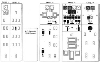
AFTER GENERATOR AND DISTRIBUTION SWITCHBOARD
692 CLASS
FIG. 74
156
A1 A2 A.C. Generator Circuit Breaker
B1 B2 D.C. Generator Circuit Breaker
C1 C2 D.C. Bus Tie Circuit Breaker
D1 D2 A.C. Bus Tie Circuit Breaker
E1 E2 A.C. Lighting Circuit Breaker
F1 F2 A.C. Battle and General Power Circuit Breaker
G1 G2 Emergency Generator Bus Circuit Breaker
- H2 Shore Power Circuit Breaker
DD 692 CLASS
GENERATOR AND DISTRIBUTION SWITCHBOARDS
FIG. 75
157
generator arid the bus tie. The synchroscope (4) is turned on by means of the synchroscope switch (4a) and the generator speed is again adjusted with the governor motor control switch (10) until the synchroscope indicator is moving very slowly in the "Fast" direction. Just before the synchroscope indicator shows that the generators are in synchronism start to close the AC generator circuit breaker (A) so that it will close when the indicator shows exact synchronism of the two machines. In case of the failure of the synchroscope (4) the AC generator may be synchronized by using the synchronizing lamps (5) which can be cut in by the synchronizing lamp switch (5a). When using the lamps the AC circuit breaker (A) should be closed when both lamps are dark. After the AC generators are in parallel the outgoing generator may be removed by reducing the AC generator load, shown on ammeter (2), by operating the governor motor control switch (10) until the ammeter (2) shows approximately 10 amperes. Then the AC generator circuit breaker (A) should be tripped "Open." The DC generator load should then be reduced to zero on ammeter (13) by lowering the DC voltage control rheostat (14). The DC generator circuit breaker (B) should then be opened. The turbine of the outgoing generator
may now be secured and the frequency of the generator remaining on the line should be adjusted to 60 cycles. If both generators are to be left in operation with the plant split and load divided between the two, the DC bus tie switch (C) and the AC bus tie switch (D) should be opened (instead of reducing the load and opening the DC and AC breakers) leaving the two switchboards disconnected from each other, each receiving power from its own generator. UNDER NO CIRCUMSTANCES SHOULD THE TWO GENERATORS BE ALLOWED TO CONTINUE OPERATION IN PARALLEL FOR MORE THAN A VERY SHORT PERIOD OF TIME UNLESS AN ELECTRICIAN'S MATE IS PRESENT TO PROPERLY DISTRIBUTE AND EQUALIZE THE LOAD BETWEEN THE TWO GENERATORS. If this is not done serious damage may result. If it is determined by the electrician's mate that it is desirable to continue operating the generators in parallel he may equalize the load by shifting the controls for the after generator to the forward switchboard. This is done by use of the governor motor transfer switch (9) which allows the governor motor control switch (21), for DD445 class or (10) for DD692 class on the forward board to control the after generator.