The feed water system can be broken down, for better presentation, into three separate systems: first, the main feed booster system; second, the main feed system; and third, the emergency feed system. With one exception, the elements of all these systems will be discussed before discussing the piping system. The main feed booster system is that part of the feed system in which water flows from the deaerating tank through the main feed booster pumps and up to the suction of the main feed The main feed system is that part of the system which carries water from the main feed pumps into the boilers. The emergency feed system is that part of the feed system through which water can be fed into the main feed system through the emergency feed pump and through which water can he transferred from one plant to another. The one exception, which will be discussed after the discussion of the feed piping, is the feed water level regulator which is so closely related to the boiler that it is best described just before starting the description of the boiler.
2. MAIN FEED BOOSTER PUMP
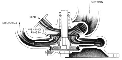
(a) General Discussion.-The main feed booster pump takes suction from the deaerating tank. This is a vertical, centrifugal, single-stage pump. which operates in principle the same as the main condensate pump except that there is only one impeller in this pump. Normally, since the deaerating tank is under pressure, the suction of this pump is also under pressure. The flow of water through this pump is the same as that described for the condensate pump with the exception, of course, that there is only one stage. This pump operates under a total head of approximately 35 p.s.i. This means that the difference between suction and discharge pressures must equal 35 p.s.i. That is, if the suction pressure is 15 p.s.i. at full load the pump will discharge 50 p.s.i. Normally the deaerating tank will carry from 13 p.s.i. to 15 p.s.i. pressure. This, plus the head of water above the booster pump suction, will make the booster pump full load discharge pressure about 50 p.s.i.
(b) Wearing Rings.-In this pump there are two sets of wearing rings of approximately the same design as those in the condensate pump. The clearance between these rings is approximately 0.008 inch, and they should be renewed when they wear to 0.030 inch. The upper rings shown seal the discharge from the suction side and the lower rings seal the discharge from passing back into the suction side through the equalizing ports of the impeller.
(c) Driving Mechanism.-In the DD445 class destroyers there is installed one electrically driven main feed booster pump and one turbine-driven main feed booster pump. The motor of the electrically driven pump is directly connected to the pump shaft. Therefore they run at the same speed, approximately 1,150 r.p.m. Externally the steam pump appears to be the same as the steam main condensate pump. The turbine operates at approximately the same speed as that of the condensate pump (5,300 r.p.m.), while the pump end operates at approximately 1,150 r.p.m. The major difference between the main condensate and the main feed booster pumps is in the capacity of the two pumps. The capacity of the main feed booster pump is approximately 455 g.p.m.. while that of the condensate pump is approximately 325 g.p.m. Time need for the increase in capacity of the main feed booster pump is because of the drains and auxiliary exhaust steam which enter the deaerating tank. This makes the volume of water entering the deaerating tank, from all sources, considerably greater than the volume of water entering the deaerating tank from the condensate line. Whenever it is necessary to operate more than one main feed booster pump it is essential that the same number of main condensate pumps be in operation in order to insure sufficient water for suction to the main feed booster pump. In the DD692 class, both main feed booster pumps are turbine driven pumps.
(d) Lubricating Oil System.-The same lubricating oil system is installed on the main feed booster pump turbine as that on the main condensate pump turbine.
670586i-46-4
35
MAIN FEED BOOSTER PUMP
FIG. 20
(e) Limit Speed Governor.-The limit speed governor which controls the main feed booster pump is of the same design as that controlling the main condensate pump. There is one difference, however, and that is that the total governor travel of the main feed booster pump should be adjusted to three-sixteenths inch instead of the one-fourth inch specified for the condensate pump.
(f) Operation.-The normal operation of this pump is with a deaerating tank pressure of 13 to 15 p.s.i. It is not essential to have more than atmospheric pressure to the suction of the pump in order to prevent it from overheating. This means that the pump can be operated with the deaerating tank under no pressure if the temperature of the water is less than 212 degrees F. It is not possible to put a vacuum on the suction side of the main feed booster pump since the deaerating tank itself is fitted with a vacuum breaker to prevent the formation of such vacuum in the tank. Should the deaerating tank become empty, however, the pump will run for only a few seconds before the wearing rings will overheat and seize due to the lack of circulation of water in the pump to carry away the heat. If the pump is operating
and discharging against a closed valve, there will be no circulation through the pump to carry away this heat. Should vapor or air enter the impeller. this may vapor bind the pump and prevent the flow of water to carry away the heat. These are the same probabilities of casualty which were discussed in connection with the condensate pump. We must have means to prevent occurrence of casualty through any of these means. A vent connection is provided from the suction casing of the pump leading back to the deaerating tank, which is the original source of supply. Operating the pump with this connection open at all times will tend to prevent the pump from becoming vapor-bound. To insure against operation of the pump without flow of water through it, that is, operation when a main feed is not taking suction from the pump discharge, a recirculating connection is provided. This recirculating connection leads from the discharge line of the booster pump into the deaerating tank where it discharges above the conical baffle in the deaerating tank. This means that water passing through this recirculating line must also pass the steam control valve in the deaerating tank and thereby be scrubbed free of air. Whenever a booster pump is operating
36
without a main feed pump also in operation, this recirculating line must be open to provide continuous circulation through the main feed booster pump. A smaller recirculating line (three-fourths of an inch) is provided, bypassing around the main 2-inch recirculating valve. This three-fourths of an inch line should be open and the 2-inch valve closed when warming up the main feed pump. When the main feed pump is put on the line, discharging to the boilers, this three-fourths of an inch valve should also be closed. The recirculating line from the main feed pump, later discussed, will provide sufficient flow through the main feed booster pump should feed be suddenly stopped. It is desirable to leave the three-fourths of an inch line open when the main feed booster pump is discharging to an emergency feed pump since it, being a reciprocating pump, will take a varying suction from the booster pump. Under no circumstances should the 2-inch recirculating valve ever be allowed to remain open when a main feed pump is operating. This 2-inch valve will pass very nearly the full capacity of the main feed booster pump and, therefore, should the main feed pump be operating at the same time it might reduce the main feed pump suction pressure below that required. If the main feed pump recirculating connection provides sufficient circulation to prevent the main feed pump from overheating it will certainly provide sufficient to prevent the main feed booster pump from overheating. When warming up a plant in which the deaerating tank has been secured and allowed to get cold it should be standard practice to operate the main feed booster pump for at least half an hour, recirculating through the deaerating tank, before feeding to the boiler from that tank. This will allow the removal of oxygen which may have been absorbed during the idle period and will also provide for heating up water standing in the tank. It cannot be too greatly stressed that when a main feed pump is started up, taking suction from the main feed booster pump. the 2-inch recirculating valve from the main feed booster pump should be closed.
3. MAIN FEED PUMP
(a) General Discussion.-The main feed pumps installed in both the DD445 and DD692 classes are horizontal pumps directly connected to their driving turbines. The impellers of some are either double or single entry and others have both single- and double-entry impellers. Some are two-stage
and some are three-stage pumps, but the action of water in all and the necessary precautions are the same. There are two of these pumps installed in each engine room, both turbine driven. The speed of rotation is very high, approximately 5,500 r.p.m. Since the pumps are directly connected to their driving turbines, the pump impellers operate also at the same speed.
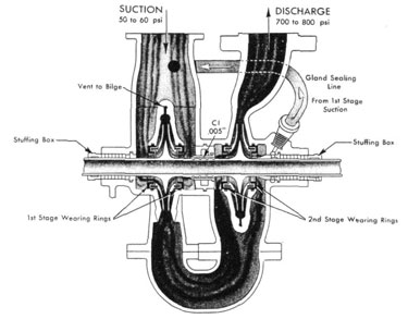
(b) Operation.-The main feed pumps take their suction directly from the discharge line of the main feed booster pump. This means that the suction to these pumps is under a normal pressure of from 50 to 60 p.s.i., depending upon the load on the pump. Figure 21 is a sketch of a Buffalo pump. As indicated previously, the action within this pump is very similar to that within all other main feed pumps. Water enters the first-stage suction casing from the main feed booster pump under pressure and is discharged through the first-stage impeller into a built-in connection which leads to the suction of the second-stage impeller. Passing through the second-stage impeller, water is discharged under high pressure (approximately 750 p.s.i.), into the main feed line. There are two sets of wearing rings in each stage since the impellers are double entry. The designed clearance for these rings is approximately 0.008 inches. Since these rings have the same clearance as those in the condensate and feed booster pumps, and the pump speed of rotation is five times as great, it is obvious that the possibility of seizure of the rings is also much greater. This pump is subject to the same casualties as the main condensate and main feed booster pumps, and is even more subject to these casualties due to the high speed of rotation of the pump. Water entering the suction of the first stage from the booster discharge line has its pressure reduced while passing through the entrance ports and since this water is under a temperature of about 240 degrees F., this reduction in pressure might easily be the cause of the water flashing into steam. Should this occur the first-stage impeller will become vapor bound and prevent the flow of water to the pump to remove the generated heat. Should this pump become vapor bound it will require only about 15 seconds for the pump to overheat and seize, due to the high speed of rotation. It is essential that the pressure leading to the pump suction from the main feed booster be maintained at as high a level as possible. Under no circumstances should a main feed pump ever be turned over unless there is at least 40 p.s.i.
37
MAIN FEED PUMP
FIG. 21
pressure to the suction of the pump. It should be noted in this connection that if the pressure should ever be this low there must be something wrong with the main feed booster pump. since this pump will discharge a normal pressure of approximately 50 p.s.i. Should vapor enter the pump from any source a vent is provided to carry this vapor away. This vent is only necessary in the first stage since the pressure in the second stage will prevent the accumulation of any vapor. When first starting up the pump this first-stage vent must always be open to carry away any accumulation of air or vapor which may be trapped in the pump casing.
(c) Recirculating Line.-To provide continuous circulation through the pump, a recirculating line is provided leading from the pump discharge connection and discharging into the deaerating tank. A valve is installed in this recirculating line and this valve is provided with a locking device in order that it may be permanently locked open. Under any condition of operation of the main feed pump. this valve should be locked open
to provide recirculation. The size of the line here installed is sufficiently great so that a full flow through this line would reduce the possible capacity of the main feed pump materially. Therefore, an orifice is placed in this line to insure that excessive flow will not be bled from the pump. Early installations of this orifice provided only a single plate. drilled with a three-sixteenths-inch hole. This provided sufficient recirculation to prevent overheating of the pump even though the discharge was completely shut off. However, the high velocity of the water in discharging from this single orifice was sufficient to rapidly wear away the pipe between the orifice and the deaerating tank and cause leaks to occur in this pipe. Later installations provide for multiple orifice plates, the purpose of which is to reduce the pressure by steps. thereby reducing the final discharge velocity of the water. Since this recirculating line must always be open, it is not necessary nor is it desirable to open the discharge valve of the main feed pump when warming up this
38
pump prior to putting it on the line. This discharge valve should be kept closed to protect the check valve until such time as it is desired to feed the boilers from this pump.
(d) Limit Speed Governor.-The maximum speed of this pump is controlled by a limit speed governor of the same general design as has been previously discussed. However, this governor is located horizontally instead of vertically and is on the turbine shaft. The total travel allowed the governor valve in this installation is one-fourth inch. This adjustment must always be checked and reset after a change is made to the governor setting. In order to build up the required pressure the speed of rotation of this pump, even under no load, is very high (approximately 4,500 r.p.m.). This means that the change in speed from no load to full load will he only about 1,000 r.p.m. The governor valve must start to close at some speed before the limit speed. With a limit speed adjustment of 5,500 r.p.m., the governor valve will start to close at approximately 5.100 r.p.m. This means that a condition may occur in which the constant pressure pump governor attached to this pump may be admitting more steam to increase the pump speed while the limit speed governor is reducing the steam admitted to the pump. To prevent this occurrence the limit speed governor of these pumps should be adjusted to limit the speed at a higher level than the rated speed of the pump. That is, the governor should not start to throttle the steam pressure to the pump until the rated speed has been reached. To prevent this, a limit speed setting of about 300 or 400 r.p.m. above the rated speed will be necessary. This condition is very noticeable on the Buffalo pump herein discussed, but for feed pumps of other designs there is not so great a variation.
(e) Constant Pressure Pump Governor.-As mentioned above, the discharge pressure from the main feed pump is controlled by a constant pressure pump governor installed in the steam supply line to the pump and actuated by the discharge pressure from the pump. Its purpose is to maintain a constant discharge pressure from the pump under all conditions of loading. Some main feed pumps are fitted with the Foster constant pressure pump governor and some with the Leslie constant pressure pump governor. A following paragraph will present a discussion of the Foster constant pressure pump governor. The Leslie governor is
discussed ill connection with the main lubricating oil pumps. Since the action of this governor is the same as that of the Leslie governor as applied to the main feed pump it will not be necessary to make two explanations. This discussion of the Leslie governor appears under section VII, paragraph 6.
(f) Lubricating Oil System.-Installed with this pump is a self-contained lubricating oil system consisting of a pump, oil cooler, and sump tank. The sump tank is located in the base of the pump and the oil pump takes its suction from there. It discharges through the oil cooler and into a header which leads oil to all bearings. A relief valve is connected to this header which discharges into the sump tank. This valve starts to lift at 10 p.s.i. and should maintain the oil pressure to the bearings at some level between 10 p.s.i. and 15 p.s.i. Due to the high speed of operation of this pump, it is essential that the pump never be brought up to full speed until the temperature of the oil reaching the bearings is at least 90 degrees F. In general, the center bearing of these pumps will be the hottest of the three and should operate at a discharge temperature of between 150 degrees and 160 degrees F.
(g) Operating Notes.-The pump should always be warmed up with the constant pressure pump governor bypassed and steam admitted by using the throttle valve. When the pump is ready to put on the line the constant pressure pump governor may then be cut in. The following is a list of details to check when warming up the main feed pump:
1. Check lubricating oil level in sump.
2. Check circulating water in lubricating oil cooler. Have water outlet valve from cooler closed.
3. Open suction valve.
4. Check suction pressure-should be at least 50 p.s.i.
5. Check recirculating valve-should be locked open.
6. Open first-stage vent.
7. Open all drains.
8. Open exhaust valve.
9. Bypass pump governor.
10. Crack throttle valve.
11. When drains blow steam, close them.
12. Bring up steam pressure to turn over pump at sufficient speed to set up oil circulation in lubricating oil system.
13. When first-stage vent drains solid water, close it until it is just cracked.
14. Run pump at about 1,500 r.p.m. until the lubricating oil sump temperature reaches 90 degrees F.
15. It is not necessary to open the discharge valve until ready to put the pump on the line. In
39
the case of the Worthington main feed pump it must be put on the line within ten minutes after starting. The Buffalo and DeLaval pumps can he idled for warming up indefinitely.
16. When pump is on line, close the first-stage vent fully.
4. CONSTANT PRESSURE PUMP GOVERNOR
(a) General Discussion.-As previously mentioned, the constant pressure pump governor which controls the main feed pump may be furnished by either the Foster Engineering Company or the Leslie Company. Since the Leslie governor is described (p. 91) in connection with the lubricating oil pumps, the Foster governor will be here described in connection with the main feed pump. This governor is bolted into the auxiliary steam line leading to the main feed pump turbine and controls the steam admitted to the turbine, varying this steam pressure to maintain a constant discharge pressure from the pump.
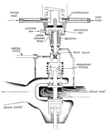
(b) Operation.-The function of this governor is to vary the steam pressure to the turbine (and consequently the turbine and pump speed) in order to maintain a constant discharge pressure from the pump under varying capacity requirements. It is apparent that some means must be applied to make the changes in capacity requirement cause corresponding changes in opening of the governor valve. With the pump operating at a specified speed, an increase in capacity requirement will cause a decrease in discharge pressure, and a decrease in capacity will cause an increase in discharge pressure. It is these changes in discharge pressure which are used to accomplish actuation of the governor valve. Figure 22 shows a connection labeled "water inlet," at the upper left, which leads into the space between two diaphragms. This "water inlet" is connected by means of an actuating line to the pump discharge and therefore carries the discharge pressure of the pump. The two diaphragms are mechanically tied together by the arrangement shown. It will be noted that the area of the upper diaphragm is greater than the area of the lower diaphragm. The water discharge pressure of the pump will be exerted against both diaphragms but, since the area of the upper diaphragm is greater than that of the lower, the total force exerted will be in an upward direction. Opposing this upward force is a spring pressing down on the upper diaphragm. It is the balance between the spring force and the
resultant upward force on the diaphragms which ultimately causes operation of the governor valve. Should the spring force be greater than the upward force on the diaphragms they will be forced downward. The adjusting nut (fig. 22) is threaded to the diaphragm assembly, so the downward movement is transmitted through this nut tot he upper sealing plug. The upper sealing plug, being in contact with the pilot valve stem, pushes the pilot valve open. The illustration shows a port leading from the steam inlet of the governor valve to the pilot valve. Opening the pilot valve allows steam to pass through to the top of the opening piston. The pressure of this steam forces the operating piston down, opening in turn, the governor valve. This admits more steam to the pump turbine causing it to speed up and the discharge pressure to increase. This increase in discharge pressure causes the upward force on the diaphragms to become greater than the spring force and the diaphragms will move upward. This will raise the adjusting nut and, releasing the pressure on the upper sealing plug, allow the pilot valve to close down. The consequent reduction in steam flow to the operating piston causes the pressure there to be reduced, through the hole shown in the piston. This reduction in pressure allows the governor valve to be closed by the spring shown in the base of the valve. If all elements of the governor are properly adjusted these changes in position of the valve occur so rapidly that the valve maintains an apparently fixed opening delivering an apparently constant steam pressure to the turbine. This is reflected in what appears to be a constant discharge pressure. In view of the change in discharge pressure which accompanies a change in capacity requirement it is easy to see that an increase in capacity (with its consequent decrease in pressure) will cause the governor valve to be adjusted to a wider average opening, and a decrease in capacity will reduce the opening. These changes in volume of steam flow to the turbine will speed up or slow down the pump to restore the pressure to normal at the new capacity.
(c) Adjustments.-The major adjustment which is made to the governor is adjustment of the force of the spring which works in opposition to the force of water pressure on the diaphragms. Increasing the tension of this spring will, by requiring an increase in water pressure needed to balance it, cause the pump discharge pressure to be increased. Conversely a reduction in the spring tension will
40
THE FOSTER PRESSURE REGULATING VALVE
FIG. 22
cause a reduction in discharge pressure. This adjustment is made through an adjusting screw at the top of the valve. The adjusting nut (fig. 22) makes a highly important adjustment to the governor. An inspection of the illustration will show that turning this nut will cause the diaphragm assembly to be raised or lowered, allowing the diaphragms to be adjusted to their most advantageous operating position. Experience has shown that, in general, the best position is obtained when, with
the adjusting spring backed off completely, the pilot valve is open sufficiently to cause admission of from 50 to 75 p.s.i. of steam to the pump turbine. This adjustment should be made either with the adjusting spring backed off fully or with full operating pressure on the unit. The needle valve shown in the illustration is used to make the third adjustment to the governor. This valve allows steam to bleed from the outlet side of the pilot valve into the governor valve discharge. Bleeding away this
41
BOOSTER PUMP SUCTION AND DISCHARGE
FIG. 23
42
small amount of steam reduces the size of the changes in steam pressure on the operating piston and reduces the amplitude of the oscillations of the governor valve. This prevents the governor from "hunting" or delivering a varying pressure. In general, it has been found that from one-half to three-quarters of a turn, open, will be a proper adjustment of the needle valve. However, experimentation with each valve may be necessary to establish the best adjustment. Attached to the base of the governor is a stem which, working in a yoke on the governor valve, is capable of manually pulling the valve open thus effectively bypassing it and making it necessary to control the pump speed with the throttle valve. The pump should always be warmed up with the governor bypassed, and the governor put into operation when the pump is ready to go on the line.
(d) Notes.-The short life of the two-ply adnic metal bellows enforced the substitution of monel (stamped "Monel Anneal" on the slotted bellows head to identify it). A recent change in the General Specifications for Machinery (subsec. S47-6) precludes the use of bellows in the pump governors, therefore the Foster type 38P5 governor has been removed from the list of Acceptable Material.
5. FEED BOOSTER SYSTEM PIPING
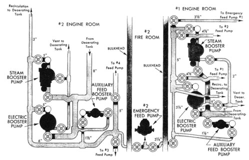
(a) General Discussion.-Though the feed booster system is actually a part of the main feed system, it can best be treated as a separate system. In this system water is taken from the base of the deaerating tank and discharged to the suction of the main feed pumps. The machinery included consists of two main feed booster pumps, both steam-driven or one steam-driven and one electrically driven, and one electrically driven auxiliary feed booster pump. The auxiliary feed booster pump is very similar in design to the main pumps but is considerably smaller. The discussion of piping which follows in detail is of the forward system. Later, differences between the two systems will be discussed.
(b) Piping.-All three of these pumps take suction directly from the deaerating tank where the water temperature will be normally from 225 degrees to 250 degrees F. The main pump suctions lead through and 8" line which branches into two 6" lines, one leading to each pump. The auxiliary pump takes its suction directly from the base of the deaerating tank through a 3 1/2" line. The suction valve leading
into each pump is a gate valve. The main pumps discharge through a vertical check valve and another gate valve into a 4 1/2" riser which leads into a common 5" discharge line. From this 5" line are led the two 4 1/2" main feed pump suction lines, with a gate valve in each to serve as the main feed pump suction valves. Passing to starboard, the 5" line reduces to 3 1/2'' and, passing through a gate valve, leads aft, where it finally joins with the after system to provide the cross-connection line between the two. Leading to port from the 5" main line, another 3 1/2" line runs through a gate valve and then leads forward to the suction manifold of the No. 1 emergency feed pump in the forward fireroom, thus providing the hot suction line for that pump. For each booster pump suction casing a 2" line leads back to the deaerating tank to serve as a vent from that pump, with a valve located at each pump. From the 5" main line, a 2" recirculating line leads also back into the deaerating tank and discharges into the tank at a point which is above the conical baffle, so that water recirculating through the line must pass the steam control valve and there be deaerated. Around the 2" valve, located in this line, is installed the previously-noted 3/4" bypass. This bypass provides for reduced recirculation of the main feed booster pump when warming up the main feed pump or when discharging to the emergency feed pumps and it also provides a small recirculating line for use by the auxiliary feed booster pump. In general, the after system is arranged similarly to the forward system but the common discharge line from the main feed booster pumps is here a 6" line and leads to starboard and forward through the engine room up to the main feed pumps. The reason for the increase in size of this line is due to the further distance the water must travel before reaching the main feed pump suctions. Branches lead to the main feed pump suctions from this line and beyond these branches, the main line continues forward as a 3 1/2" line. Passing into the after fireroom, this line joins the cross-connection leading from the forward engineroom. Above the No. 2 emergency feed pump in the after fireroom will be noted two cut-out valves. From between these two valves the hot suction line leads to the suction manifold of No. 2 emergency feed pump. By means of this cross-connection line it is apparent that any booster pump can discharge to any main feed pump or to
43
MAIN FEED SYSTEM
FIG. 24
either emergency feed pump. Note The piping sizes indicated apply to the DD445 class, however, the arrangement of piping for the DD692 class is similar.
(c) Operating Instructions.-When warming-up in an engine room which has been secured, and thereby has a cold deaerating tank, it is necessary to recirculate water from the main feed booster pump back through the deaerating tank for at least half an hour before feeding to the boilers. In the case of a cold tank the feed water has been standing in the base of the tank with air above it and has consequently absorbed some of this air. To prevent the discharge of this air into the boilers the above operation is necessary to deaerate all this idle water. Whenever it is necessary to have more than one main feed pump in operation in each engineroom it is also essential that both main feed booster pumps be in operation. The full capacity of each main feed booster pump is only slightly more than that of each main feed pump and, therefore, if two main feed pumps were operating and only one main feed booster pump, the capacity of the two main feed pumps could easily surpass that of the single booster pump. This would cause a reduction in the booster pump discharge pressure below
that required for the main feed pump suction, consequently causing damage to the main feed pump.
6. MAIN FEED PIPING
(a) General Discussion.-The accompanying drawing of the main feed system has been simplified to show only those valves used in casualty control. This means the elimination of the pump discharge valves. This main feed system is as flexible and simple a system as could possibly be desired. A later discussion will show that except in two specific points no single casualty to the main feed line could cause the need to permanently secure any boiler and in no case would speed have to be reduced below half power.
(b) Piping System.-The loop shown passes through three of the engineering spaces only. The connection from the after engineroom consists only of the pump discharge line which joins the loop on the starboard side of the after fireroom. The discharge line from the forward pumps enters the loop on the port side, aft, of the forward engineroom There is in each fireroom a cutout valve on both sides of the loop which will allow water to flow to the feed checks, in that fireroom. from either side. In the after fireroom, a group of three
44
valves will he noted. One of these cuts out feed from the after pumps. The center of these three valves cuts out feed from the starboard side. The forward of these. three valves is the cut-out valve for the starboard leg of the feed loop. The discharge line from the forward main feed pumps enters the loop between two cut-out valves which allow water to be led either forward or aft. Since this feed system is not provided with auxiliary feed checks, the emergency feed pumps discharge directly into the main feed line, the forward pump leading in between the port cut-out valve in the No. 1 fireroom and the feed checks. The after emergency feed pump leads into the loop before the cut-out valve on the starboard side but between the other two valves, the presence of these other two valves making it possible for the emergency feed pump to discharge to the after boilers without going into the rest of the feed line. A thorough inspection of this piping system will show that the only casualty that can cause any boilers to be entirely without feed must occur in that leg of the line which passes athwartship between the boilers. Casually in any other part of the system may reduce the feed available to half capacity but all four boilers can at least be fed. In some instances full capacity may be maintained by paralleling the four pumps. In this case, however, it would then become necessary to operate the entire plant in parallel to maintain the balance of the condensate.
(c) Operating Instructions.-Since these plants are to be normally operated divided ("split-plant") the main feed system must also be divided. In doing this, it is required that pressure be kept away from as much of the feed line as possible, thereby reducing the area subject to casualty. This means that the valve leading aft from the forward pump discharge, and the port cut-out valve in the No. 2 fireroom be closed. This will allow water to be led forward from the forward pumps and will keep pressure away from that section of line between the forward engineroom and the after fireroom. The starboard leg should be lined up with the cutout valve which leads forward from No. 2 fireroom closed, and the starboard cut-out valve in No. 1 fireroom closed. If the other two valves on the starboard side of the after fireroom are open, we can then lead feed to the after boilers from the after main feed pumps and also keep pressure away from the long run of pipe leading
up the starboard side of the ship. Any casualty occurring, then, to these empty sections of pipe will not affect operation of the plant at full power. Should a casualty occur in the discharge line from the after main feed pumps this will, of course, necessitate paralleling of the four boilers on the forward pumps but still allow parallel operation at half power. A casualty to the port leg of the loop leading into the forward fireroom would necessitate cutting out that leg but paralleling all four pumps through the after fireroom and feeding the forward fireroom from the starboard side would still allow parallel operation at full power.
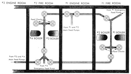
7. EMERGENCY FEED PIPING
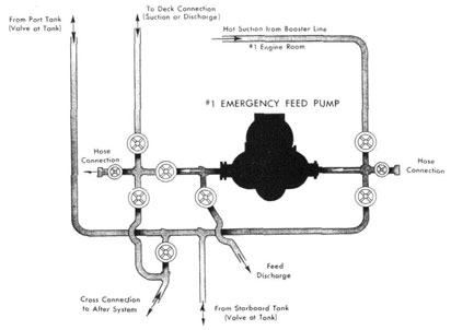
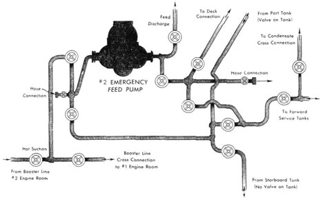
(a) General Discussion.-As previously noted, there is no separate system for feeding the boilers in emergency, since the discharge from the emergency feed pumps leads directly into the main feed line. However, a system is built up around the emergency feed pump which will provide for transferring feed water from one plant to another, will allow cold water to be discharged directly to the boilers or will allow for washing out boilers with fresh water and also provide a means of discharging water from the reserve feed tanks overboard or to another ship. The following discussion applies to the forward fireroom of the DD445 class destroyers. Differences between this and the after fireroom will be later noted, with the differences being apparent on figures 25 and 26. Figure 27 shows the arrangement in the DD692 class. The minor change shown here is not sufficiently important to warrant a separate discussion but will also be noted.
(b) Piping System.-The suction manifold of the emergency feed pump consists of two valves and a hose connection. One of these valves, as indicated in figure 25, is connected to the feed booster discharge line and provides for suction by the emergency feed pump from that line. This connection is called the hot suction line. The other valve is connected to a line which branches athwartship and leads to the two reserve feed tanks in this fireroom. At each tank a cut-out valve is provided. This will allow the emergency feed pump to take cold suction directly from either of the reserve feed tanks. The hose connection on this manifold can be hooked up any way it may be desired by using a portable hose. From the cold suction line a branch leads to starboard and then aft through the after engineroom and into the
45
EMERGENCY FEED SUCTIONS
#1 FIRE ROOM
FIG. 25
after fireroom. In this line there is a cut -out valve in the forward fireroom just after it leaves the cold Suction line. The discharge manifold on this pump is in reality two manifolds; one is a single valve which leads directly into the main feed line, the other ma be cut off from this single valve and is a low-pressure manifold being protected by a 100 p.s.i. relief valve. As shown on the sketch, one valve of the low pressure manifold leads up to a deck connection to provide the means for discharging water overboard from the reserve feed tanks. Another valve leads into the branch line previously mentioned on the outlet side of the cutout valve. Discharging through this last valve will allow us to pump water through this branch line and, since it joins with the after system, will allow that water to be pumped into the after system. A hose connection is also provided on this manifold. Arrangement of the after emergency feed piping is very similar. The hot suction connection, however, rises to the booster cross connection
line in the fireroom between the two cut-out valves, as previously discussed in connection with the booster system. From the reserve feet! tanks suction lines lead to the cold suction valve of the manifold. From this suction line a branch also leads forward and joins with the branch leading from the forward system. In this line before leaving the fireroom there are provided two cut-out valves. The arrangement of the discharge manifold is the same as that. forward, with the low pressure manifold having one valve which leads between the two cutout valves in the cross-connection line. From this cross-connection line a 1-inch pipe leads overhead and, behind No. 3 boiler, joins the condensate cross-connection line. A valve is provided to cut out this line.
(c) Operating Instructions.-An analysis of this system shows that either emergency feed pump can take suction from either pair of reserve feed tanks and discharge into the main feed line. Either pump can take suction from its own pair
46
EMERGENCY FEED SUCTIONS
#2 FIRE ROOM
FIG. 26
of reserve feed tanks and discharge into the tanks of the other fireroom. Either pump can discharge into its own tanks only when taking suction from the booster line or from the suction hose connection. If pressure is placed upon the cross connection line, water can be led through the previously mentioned 1-inch line into the condensate cross connection for the purpose of filling either or both deaerating tanks. It should be especially noted that when transferring water from one pair of tanks to another the pump must be used which is in the space from which the water is to be taken. When the emergency feed pump is operating with its suction coming hot from the booster line the pump cylinder and valve chest become heated. As long as pressure on the booster line is maintained. water entering the pump will not flash into steam, but if it becomes necessary to shift to cold suction the heat in the pump and valve chest will, when the cold water enters under atmospheric pressure or less, cause it to flash into steam thereby vapor binding the pump. It may take from 10 to 15 minutes to sufficiently cool the pump cylinder so
that it can take a cold suction. This shift should be necessary only when a casualty causes loss of the booster pressure and, since the main feed pumps are always used underway. could reasonably be expected to occur only on auxiliary watch. In this case, feed water could undoubtedly he delivered to the boilers in shorter time by starting the emergency feed pump in the other fireroom on cold suction. When underway, both hot and cold suction lines should always be open directly to the emergency feed pump manifold with only the manifold valves closed. If it is desired to keep the pump warmed up by allowing it to turn over very slowly this should be done with the cold suction valve open and not. the hot suction valve. The pump will then remain cold and if it is required to be put on the line the suction can be shifted from cold to hot without trouble. However, if the pump is turning over on the hot suction and the shift is necessitated by loss in booster pressure, causing securing of the main feed pumps, the shift to cold suction cannot be made in time to prevent a casualty.
47
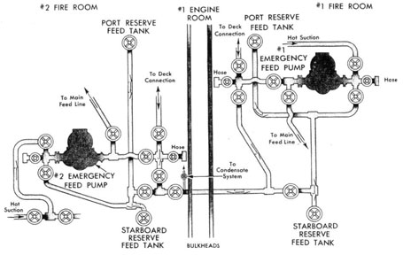
EMERGENCY FEED SYSTEM
692 - CLASS
FIG. 27
(d) DD692 Class.-The change in the emergency feed piping between the DD445 and DD692 class occurs in the forward fireroom only. Here the discharge from the low pressure manifold of No. 1 pump leads to the starboard side, there joining the cross-connection line as shown. The use of this arrangement has reduced somewhat the amount of piping required, while making it necessary to go to the starboard side to line up the cross connection into the forward reserve feed tanks.
8. FEED WATER LEVEL REGULATOR
(a) General Discussion.-This piece of equipment is being discussed after the main feed system although it is an integral part of that system. It is so closely related to the operation of the boilers that it is necessary to discuss it just before the boiler discussion. The purpose of this regulator is to vary the feed water discharge into the boiler in such a manner as to maintain a constant water level in the boiler. The valve in this unit is flanged directly into the main feed line between the feed
check for each boiler and the economizer. In general, destroyers are fitted with two makes of feed water regulators although the earlier ships may have none installed. One is the Bailey regulator and the other the Swartwout regulator. The general arrangement and principle of operation of both these regulators is almost the same and, therefore, the discussion will be confined solely to the Bailey regulator.
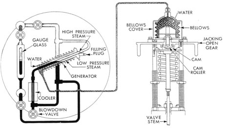
(b) Operation.-This installation consists of a generator assembly, the regulating valve assembly and the connecting piping. The generator assembly is arranged with its connecting piping on the front of the steam drum as shown in figure 28. with the generator centered across the normal water level of the boiler. The regulating valve assembly is connected with the valve itself in the main feed line and with its bellows attached to the generator by means of a length of copper tubing. The generator consists of two pipes, the internal pipe. which is connected, by the arrangement shown, to the gage glass fittings of the boiler, and an external
48
pipe which is connected to the valve bellow through the copper tubing. There is no connection between the internal and external pipes. Their inner spaces are entirely separate, with the internal piping running only through the outer pipe and the outer pipe welded at top and bottom to the inner pipe to hold it in place. When the valves from the gage glass fittings to the internal pipe are open, water will naturally rise in the internal pipe to the same level as that in the gage glass and will, in fact, reflect the water level in the boiler. Above this level the internal pipe with its connecting lines is full of steam. The generator or external pipe is, before being placed in operation, completely full of water as are the copper tubing and the bellows oft he valve assembly. This external system is entirely enclosed and the water is at atmospheric pressure before steam and water are allowed to enter the internal pipe. When steam and water enter the internal pipe the steam, being under high pressure, is at a high temperature. Heat will be transmitted from this steam through the internal pipe into the water surrounding it in the generator. Since the water in the generator is under atmospheric pressure this water will commence to form steam. As steam forms in the generator pressure will be built up in the generating system and this pressure, being transmitted through the copper tubing to the bellows, will cause expansion of the bellows. As is readily apparent in figure 28 the valve stem of the regulating valve is in contact with the cup which encloses the bottom of the bellows. Expansion of the bellows will cause this cup to be forced downward, pushing with it the valve stem, thereby opening the regulating valve. With the unit in operation, if the level of water drops in the boiler the level of water in the inner pipe will also drop. There will be a greater area of the inner pipe full of steam. This will transmit more heat into the generating system, generate more steam and cause the pressure to rise. This rise in pressure will in turn cause the bellows to expand further and further open the regulating valve, thus allowing more water to enter the boiler to restore the level to normal. When the water level in the boiler rises we have a corresponding rise in water level in the inner pipe. The water which enters the inner pipe, due to this rise, has been standing in the cooler, located as shown on the sketch. This means that this water will be relatively cool, and on entering the internal pipe will cause condensation
of some of the steam in the generator. This will naturally reduce the pressure in the generator, causing the bellows to contract and allowing the regulating valve to close. The instant steam begins to form in the generator pressure will also start to build up and if nothing opposed the expansion of the bellows, it would start to expand and open the regulating valve. If this were allowed the valve would be open, allowing feed to enter boiler with a very high water level in the boiler. In order to prevent this a spring, installed as shown in the sketch of the valve assembly, opposes the opening of the valve. The force of this spring is approximately 600 pounds which means that a pressure of approximately 45 p.s.i. must be built up in the generating system before the bellows can start to expand in opposition to this spring pressure. The point of water level at which 45 p.s.i. pressure is built up is about 3 inches above normal level. With the water level 3 inches below normal a pressure of about 60 p.s.i. will have been built up in the generating system. This is sufficient to force the regulating valve wide open. To sum this up, if the water level is 3 inches above normal, the valve is fully closed and if 3 inches below normal the valve is wide open.
(c) Operating Instructions.- It should be especially noted that the spring force above mentioned is always tending to close the valve. This being the case, should anything happen to cause the generating system to reduce its pressure below 45 p.s.i., the valve will close entirely and cease feeding water to the boiler. This could occur through a leak in the generating system or through a puncture in the bellows or any part of the generating system. Because of this it is essential that the check man be even more attentive to his gage glass than if he were feeding by hand. It is apparent that a man on watch feeding by hand would, if he left the checks, leave them at least partly open even though this may be not quite sufficient for a normal feed. Under these circumstances it would take some time before the water level would drop out of sight. However if he were operating the feed water level regulator and the generating system were punctured while he was not watching the glass the valve would close off entirely and admit no feed whatever. Even at reasonably slow rates of steaming it would take only a very short time before water would be out of the glass entirely. The feed water level regulator is very effective when operating at constant speeds, but when
49
THE BAILEY FEED WATER LEVEL REGULATOR
FIG. 28
maneuvering will have a tendency to lag behind the change in steaming rate of the boiler. For a single maneuver it would maintain the water level very nicely but for more than one, it is apt to get so far behind that it is more desirable to shift to feeding by hand. However, the regulator should always be used in action since, should a casualty occur which would incapacitate the check man, the regulator will maintain water level in the boiler. Since the regulating valve is directly connected into the main feed line it must be fitted with some means to jack it open mechanically when it is desired to feed by hand. This is accomplished by means of a cam attached to the valve stem and a cam roller which is rotated by means of two levers. Operating the levers, the roller rises to the high point, of the cam and since the roller is allowed no vertical movement the cam is driven down carrying with it the valve stem and consequently opening wide the regulating valve. In figure 28 the arrangement of this cam and roller is shown. Under normal conditions if time water level in the boiler is held at a point which is higher than that desired it can be maintained at a lower point by bleeding steam pressure from the generating
system when it is in operation. This will reduce the pressure in the generating system and allow less water than normal to be delivered to the boiler. If this is done pressure can be bled off without allowing air to enter the system. Should air enter this system a constant pressure could not be maintained. Therefore, it is essential that all air be excluded at all times from the generating system. Should the water level be carried at a point which is lower than that desired it can be most effectively raised by increasing the feed water pressure. Another method of varying the normal water level carried is by changing the tension of the spring in the valve assembly. This method is not very effective since the maximum change of water level obtainable will be about one-half inch only. The method of filling the generating system, outlined in the manufacturer's instruction book should be very carefully followed. The feed pressure recommended to cause best operation of the unit is about 775 p.s.i. At very high rates of feed the regulator will tend to carry a rather low level. In order to overcome this it is recommended that the feed pressure be carried as high as possible whenever boilers are operating at nearly full load.