Depth charge release tracks which are designated by type letter are those designed for installation on small vessels and motor boats ; or those found installed in multiple along the side of somewhat larger antisubmarine vessels. A common feature of them all is that wire pendants are used to retain the depth charges in the tracks, and that all have only local release gear.
There are four of these tracks, Types A, B, C, and D. Types A and C accommodate only one depth charge and Types B and D accommodate two charges. 17.625-inch Depth Charges Mks 6, 8, 9, and 14 can all be used with these tracks.
Depth Charge Release Track Type A
Depth Charge Release Track Type A is a weldment, consisting of angle irons and channels arranged as shown in figure 32, to form a platform on which the depth charge rests. A channel laid at an angle across the rear of the assembly forms a back rest against which the charge is held. Figure 32 shows this track as assembled for a port side installation. The overall dimensions of Depth Charge Release Track Type A are: height-31 inches, width-32 inches, length-30 inches.
Figure 32.-Depth Charge Release Track Type A.
33
Release Gear. The depth charge is retained in this track by means of a release cable. Both ends of the cable terminate in screw fittings which pass through angular guides mounted on the back rest, figure 32, and are secured by butterfly nuts. The bight of the cable passes over the depth charge and through a link which drops into a locking clevis centrally located on the front channel of the track assembly. A release pin passing through the clevis and the link, secures the bight of the cable over the depth charge. By turning up on the butterfly nuts and drawing the screws through the guides, the cable is effectively shortened, thus drawing it tight over the depth charge and snugging it against the back rest.
The release pin is attached to a crank through a clevis. The crank is mounted on a shaft which extends forward through the track structure and ends in a release crank. Rotating the crank clockwise draws the release pin out of the link, freeing the release cable and allowing the depth charge to roll out of the track. The release crank can be locked in the secure position by means of a toggle pin passed through the crank and the track structure. The pin is secured against loss by a chain attached to the track structure.
Lanyards. It is recommended that lanyards, which may be provided with these tracks, for removing safety forks and covers not be used. It has been known that shock or wave action has caused them to function prematurely if attached. Safety forks and covers should be removed by hand before releasing the charge.
Track Conversion. Figure 32 shows a track assembled with the release lever requiring clockwise rotation to release the charge. The release shaft may be mounted on the opposite side and passing through the unused hole shown in the illustration. In this case, the crank must be turned counterclockwise for release. A track can be converted for use from one side to the other by removing the release shaft, lever and pin, and mounting them on the opposite side of the track.
Depth Charge Release Track Type B
Depth Charge Release Track Type B, figure 33, is similar to Type A except. that it is long enough to accommodate two depth charges. Each charge is secured with a separate cable arranged in the same manner as in Depth Charge Release
Track Type A, with a separate release shaft and crank for each. The release cranks are locked in their secure positions by a toggle pin passing through a U-shaped bracket and through both cranks. This track also may be used with the release levers assembled on the opposite side. Its over-all dimensions are: height-34 inches, width-32 inches, length-48 inches.
Loading Type A and B Tracks
To load a depth charge into a Type A track proceed as follows:
1. Remove the safety pin from crank.
2. Back off the butterfly nuts to get plenty of slack in the wire cable.
3. Rotate the release crank to pull the pin from the release link, then throw the cable over the back of the track.
4. Place a depth charge on the track, holding it against the back rest.
5. Drop the bight of the cable over the depth charge, place the release link into the locking clevis, and then rotate the release lever into its secure position, driving the pin into place through the link.
6. Turn up the butterfly nuts, tightening the cable, and snugging the depth charge up against the back rest.
7. Replace and secure the release crank with its toggle pin.
To load Depth Charge Release Track Type B, handle each depth charge in the same manner as above. Load the inboard charge first, and tighten the pendant securing the charge. Load the outboard charge, and snug it up against the inboard one.
Depth Charge Release Track Type C
Depth Charge Release Track Type C consists of two side plates, secured together by rear and front cross-members, figure 34. Angle irons welded inboard of each side plate form the tracks on which the depth charge rests. The tracks curve upward at the rear of the track at the same radius as a depth charge, forming a surface against which the depth charge is held. These tracks may be installed on either side of the ship without conversion, The overall dimensions of Depth Charge Release Track Type C are: height-22 inches, width-33 inches, length-22 inches.
34
Figure 33.-Depth Charge Release Track Type B.
Release Gear. The depth charge is secured in Depth Charge Release Track Type C by means of a cable with a spliced thimble in each end. The thimbles are joined by a triangular link, secured at the center of the forward cross-member by a latching toe. The bight of the cable passes over the depth charge and through pulleys mounted athwartships inside of each side plate. The pulleys are mounted on brackets and arranged with adjusting screws by means of which they may be pulled toward the side plates. This tightens the cable about the depth charge. The two legs of the cable are bridged by a galvanized strap to prevent them from sliding along the curved contour of Depth Charge Mk 9.
The latching toe which holds the triangular link is mounted in a bracket and fitted with a lever. When this lever is operated, the toe is rotated, releasing the link, casting the cable free, and allowing the depth charge to roll off the track. The operating lever can be locked in the secure (down) position by means of a pin. This is passed through the release mechanism bracket and the lever, and locked in place by a safety fork. The pin and fork are secured against loss by chains attached to the bracket.
Lanyards. Lanyards may be supplied with this track as with Types A and B, but they should not be used, as shock or wave action may cause premature removal of safety forks and covers.
35
Figure 34.-Depth Charge Release Track Type C.
Depth Charge Release Track Type C Mod 1. Depth Charge Release Track Type C may be used for planting mines from motor torpedo boats. A set of wooden liners are installed on the track and against the rear cross-member in order to let the track accept a mine. The track liners extend beyond the steel tracks and are supported by chocks and wedges. When modified in this manlier the track becomes a Mod 1. Removal of the liners converts it back to Type C.
Depth Charge Release Track Type D
This track, figure 35, is similar to the Type C except that it is large enough to accommodate two depth charges. Its over-all dimensions are: height (including charges)-28 inches, width-33 inches, length-40 inches.
There are two cables and securing mechanisms, one for each charge. The inboard mechanism is
Figure 35.-Depth Charge Release Track Type D.
225771 O-52-6
36
the same as that for Type C. The bracket and latching toe for the outboard mechanism are mounted on a horizontal crosspiece joining the side plates at the base of the track. The latching toe for this mechanism is connected by two links to an operating shaft and lever. The lever is operated by a connecting rod, extending forward to the operating lever, mounted in a bracket alongside the inboard release mechanism.
Loading Type C and D Tracks
To load a depth charge into Depth Charge Release Track Type C, proceed as follows:
1. Remove the safety fork and draw the locking pin from the release mechanism bracket.
2. Rotate the release lever to the release position. This operation opens the latching toe and frees the cable.
3. Back off the pulley adjusting screws as far as possible. Push pulleys in, giving the cable as much slack as possible.
4. Throw the cable outboard ; lay it between and clear of the rails.
5. Lower a depth charge gently onto the tracks, rolling it back against the rear curve. Retain it temporarily in place with wedges or by hand.
6. Throw the cable over the depth charge, dropping the triangular link into position behind the latching toe.
7. Return the release lever to its secure position, locking the link.
8. Replace the release mechanism locking pin and safety fork.
9. Center the cable over the depth charge.
10. Take up on the pulley adjusting screws alternately from side to side so that they are lifted equally until the cable is drawn tightly over the depth charge and holds it snugly in place.
11. If the pulleys take up against their shoulders before the cable is taut, slack them off again, place a couple of wooden wedges behind the depth charge, and then take up the screws again.
To load Depth Charge Release Track Type D, proceed for each depth charge as for track Type C. The outboard charge must be loaded first, but its pulleys left slack until after the inboard charge is loaded and snugged up. Then the outboard adjusting screws may be taken up drawing the cable taut around the charge. The use of wooden wedges as noted for Type C tracks is applicable only for the rear charge in Type D.
37
Chapter 6 DEPTH CHARGE RELEASE TRACK EXTENSIONS
Introduction
In order to increase the storage capacity of Depth Charge Release Tracks Mks 1, 3, and 7, Depth Charge Release Track Extensions Mks 1, 3, and 7 are available. Structurally, these extensions are similar to the tracks with which they are installed. They are generally supplied in pairs, assembled for port and starboard installation.
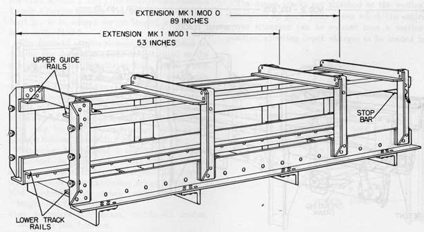
Extension Mk 1 Mods 0 and 1
Depth Charge Release Track Extension Mk 1 Mod 0, figure 36, is designed to attach to the forward end of Depth Charge Release Track Mk 1 Mods 0 or 1. It provides additional storage space for five 17.625-inch depth charges. It is a rectangular structure composed of four longitudinal angle irons joined together by side angles and upper and lower cross brace angles. The two rear side angles are pierced with holes through
which the extension is bolted to the release track. The extension is supported by suitable brackets extending from the deck to the lower cross brace angles. Small longitudinal angles mounted inside the large lower longitudinals, provide the tracks upon which the depth charges rest.
Depth Charge Release Track Extension Mk 1 Mod 1 is Extension Mk 1 Mod 0 cut down to accommodate only three 17.625-inch depth charges.
Either mod of this extension may be used in conjunction with either mod of Depth Charge Release Track Mk 1. When installing the extension, extreme care must be taken to see that the tracks in the extensions are correctly aligned with those of the track. Otherwise depth charges may jam in passing from the extension into the track.
For a special installation on PE boats, these extensions were used in conjunction with Depth Charge Release Track Mk 4. In this case, a special adapter was used because of differing
angles of slope between the extension and track and because of the dissimilar structures.
The adapter also contained a detent similar to that on the Track Mk 3 but without the free swinging pawl. This installation was not intended for general use and is now obsolete.
Depth Charge Release Track Extension Mk 1 Mod 0 is approximately 28 inches high, 36 inches wide, and 89 inches long. Depth Charge Release Track Extension Mk 1 Mod 1 is approximately 30 inches high, 36 inches wide, and 53 inches long.
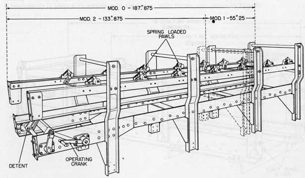
Extension Mk 3 Mod 0
Depth Charge Release Track Extension Mk 3 Mod 0, figure 37, is designed to attach to the forward end of Depth Charge Release Track Mk 3 Mods 0, 1 and 2. It provides additional storage space for ten 17.625-inch depth charges.
This extension is similar in construction to Depth Charge Release Track Mk 3, except that its longitudinal angles extend beyond its aftermost stanchion, and terminate with an angle bracket bolted to each angle. These brackets are used to attach the extension to the depth charge release track.
A single detent assembly is mounted at the rear of the extension, between the lower tracks, to hold the depth charges in the extension until needed. This detent assembly is fitted with a lever, connecting rod and crank, which serve to rotate the detent from behind the aftermost depth charge and allow it to 1.611 on into the release track. Alignment for proper operation of the detent, detent lever, and operating crank should be made in accordance with figure 38.
Pawls, similar to those found on the Track Mk 3, are installed between the upper longitudinals of the extension and have the same function as those of the track.
To release depth charges from Depth Charge Release Track Extension Mk 3 Mod 0, proceed as follows:
1. Raise the operating crank of the detent assembly to its vertical position. This will rotate the detent downward, clearing it from behind the aftermost charge.
2. Allow as many charges to roll aft into the release track as required.
Figure 38.-Alignment Diagram for Release Detents, Extension Mk 3.
3. Return the operating crank to its secure position.
4. Repeat the above cycle as necessary each time it is desired to pass depth charges into the release track.
Extension Mk 3 Mods 1 and 2
Depth Charge Release Track Extension Mk 3 Mods 1 and 2 are formed by cutting extension Mod 0 into two parts. This is done by parting the longitudinals of the extension at a point 55.25 inches aft of the forward edge of the forwardmost stanchion, and relocating the forward stanchion of the after section. The after section then becomes Depth Charge Release Track Extension Mk 3 Mod 2. It is, except for its length, exactly the same as the Mod 0.
The forward section remaining, is modified by cutting the free ends of the longitudinal to the proper slope, and by adding four angles which are used for bolting the extension to the release track. It then becomes Depth Charge Release Track Extension Mk 3 Mod 1. Extension Mk 3 Mod 1 will, of course, have no detent while Mod 2 will have the same detent as Mod 0. Either extension may be used in conjunction with Depth Charge Release Track Mk 3 Mod 0, 1 or 2.
Extension Mk 3 Mod 1 accommodates three 17.625-inch depth charges and Mk 3 Mod 2 accommodates seven of the same charges. The overall dimensions of these extensions are as follows:
Mod 0-height-53 inches, width-34 inches, length-15 feet 8 inches.
Mod 1-height-53 inches, width-34 inches, length-4 feet 7 inches.
Mod 2-height-53 inches, width-34 inches, length-11 feet 2 inches.
Extension Mk 7 Mod 0
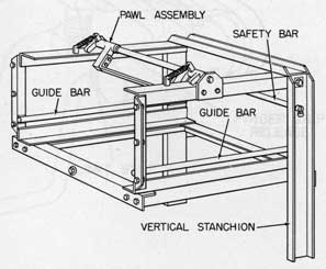
Depth Charge Release Track Extensions Mk 7 Mod 0, figure 39, is designed to attach to the forward end of Depth Charge Release Track Mk 7, increasing its capacity from two to four 17.625-inch depth charges.
The extension has two vertical stanchions at the forward end and two upper and two longitudinal angles to serve as tracks. At the rear of the assembly, two vertical angles provide a means of attaching the extension to the release track. A single pawl assembly is installed between the two upper tracks to secure the after depth charge against rolling forward, and the forward depth charge is secured by a stop bar extending between the vertical stanchions.
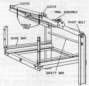
Extension Mk 7 Mod 1
Depth Charge Release Track Extensions Mk 7 Mod 1, figure 40, is similar to the Mod 0 and has the same capacity. It is used in conjunction with Depth Charge Release Track Mk 7 where space is restricted and depth charges cannot be loaded from the forward end of the extension.
The upper tracks are attached to the vertical stanchions by pivot bolts about which the entire upper structure can be rotated into a vertical position, allowing depth charges to be loaded in
Figure 39.-Depth Charge Release Track Extension Mk 7 Mod 0.
40
through the top of the extension. At the after end of the upper structure two devises are mounted, one on each side. Each clevis fits over the end of a vertical angle. The upper structure is secured in its closed position by toggle pins passed through clevis and angle.
The lower rails of Depth Charge Release Track Extension Mk 7 Mods 0 and 1 have the same weakness as those of Depth Charge Release Track Mk 7. Ordalt 1898 provides, also, for the installation of strengthening angles underneath. the rails of both mods of Extension Mk 7 in the same manner as for the Release Track Mk 7.
Maintenance of Extensions
Depth charge release track extensions have basically the same features of construction as release tracks and therefore require the same minimum of maintenance. All unpainted metal parts such as exposed bearing surfaces must be coated with preservative grease and the extension well painted.
Features requiring lubrication should be treated at the same intervals and with the same lubrication
materials as specified for similar features in the release tracks.
Figure 40.-Depth Charge Release Track Extension
Mk 7 Mod 1.
41
Chapter 7 DEPTH CHARGE RELEASE TRACK CONTROLS
Depth charge release track controls for all tracks except the Mk 7 and Types A, B, C, and D are independent units and may be used with any track except those noted above. There are three controls currently in general use: Local Control Mk 1, Hydraulic Control Mk 1, and Depth Charge Release Control (Electric-Hydraulic) Mk 3. Depth Charge Release Control (Electric-
Hydraulic) Mk 2 has been installed on a few ships, all of which are in reserve status, but no further installations will be made.
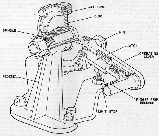
Local Control Mk 1
Local Control Mk 1, figure 41, is a hand operated control designed for use only where local operation of depth charge release tracks is desired.
Figure 41.-Local Control Mk 1-Cutaway.
42
It consists of a pedestal, mounting a spindle and disc. These are secured by a bolt passing through both. A circular housing surrounds, but is not fixed, to the outer periphery of the disc, and carries, as an integral part, the operating lever of the control. At the base of the lever there is a pin to which the connecting rod of the track release mechanism is attached. When the operating lever is thrown from one position to the other, the circular housing rotates about the stationary disc. The pin and connecting rod move from the secure to the release position and vice versa.
While it is possible to use Local Control Mk 1 on other tracks, it was primarily designed for use with Depth Charge Release Tracks Mks 4 and 5. As used with these tracks it is mounted on top of the track, figures 24 and 27. The secure position occurs when the operating lever is thrown to the rear of the track.
The stationary disc has a notch cut in it. This lines up with a spring loaded latch in the operating lever when it is in the secure position. With the latch engaged in the notch the lever is secured against inadvertent operation. A grip release is provided on the operating lever, which, when pressed, removes the latch from the notch and permits the lever to be thrown into the release position.
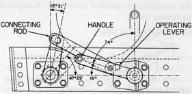
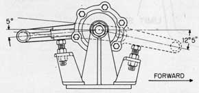
Controls are marked for port or starboard installation depending upon the orientation of the notch in the disc and the stop brackets installed. However, they may be assembled for use on the opposite side of the ship by turning over the disc so that the notch aligns with the new secure position of the control and by mounting a new set of stop brackets, built for the opposite hand. The adjustable bolts in the stop brackets should be adjusted to stop the operating lever at the angles
Figure 42.-Alignment Diagram, Local Control Mk 1.
indicated on figure 42, whichever side of the ship the control is mounted on.
Hydraulic Control Mk 1
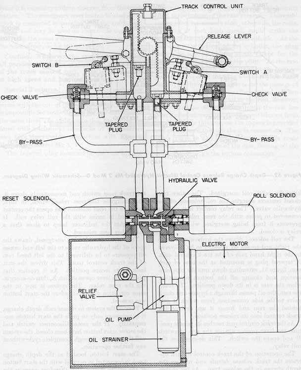
Hydraulic Control Mk 1 is a release system designed to allow either local manual release of depth charges, or release from a location remote from the release track, usually the vessel's bridge. Under remote control it is a hydraulic system consisting of a track control unit at the release track, a bridge control unit at the remote release station, hydraulic piping to connect the two units, and a surge tank located at a higher elevation than the bridge control unit.
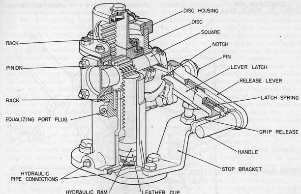
Track Control Unit. The track control unit is normally mounted on a pedestal bracket inboard of the release track where it is readily accessible for operation. A pin on the outboard side of the manual operating lever provides the assembly point for the track release gear connecting rod. The control unit is constructed so that, whether it is operated hydraulically or manually, the release lever is rotated from its secure to its release position and vice versa, thus operating the track release gear.
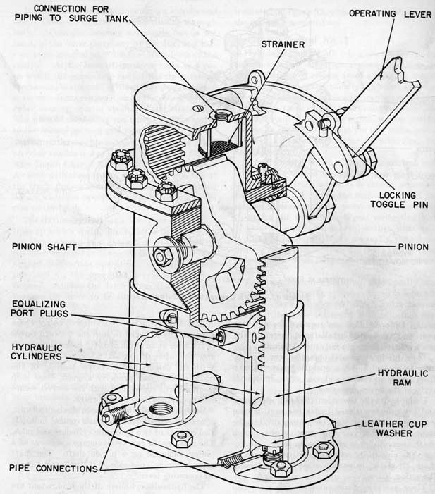
The track control unit., figure 43, basically consists of twin hydraulic cylinders bored in a bronze casting. Each cylinder contains a hydraulic ram sealed at its lower extremity with a leather cup. The upper end of each ram is only half round and has teeth machined into its fiat surface forming a rack. The racks of each ram face each other, and engage a pinion mounted on a shaft which passes horizontally through the cylinder casting. The teeth of the racks are meshed 180° from each other so that when one ram is at full throw down the other is full up.
The pinion shaft passes through a gland on the outboard side of the casting and terminates in a square. A control disc is mounted on the square and secured by a nut. Surrounding the outer periphery of the disc is a circular housing, similar to that of Local Control Mk 1, from which extends the operating lever. The control disc contains a notch cut to engage a spring loaded lever latch so that, when the latch is engaged, the disc, disc housing, and lever operate as a unit. When the grip release, behind the lever handle, is compressed disengaging the latch, the housing and lever rotate about the disc independent of the hydraulic
43
Figure 43.-Track Control Unit-Cutaway.
rams. Different discs are required for use with port and starboard installations, therefore the track control units are not interchangeable.
Thus, for local manual operation, the grip release is pressed and the operating lever thrown from secure to release and vice versa, independently of the hydraulic system.
Under hydraulic operation, the latch is engaged and pressure introduced under one ram driving it upward. This rotates the pinion, driving the other ram downward and rotating the pinion shaft, control disc, and operating lever. To return the unit to its original position, pressure is then introduced below the other ram, reversing the action.
There are pipe connections at both sides and at the bottom of each cylinder. Equalizing ports are drilled between cylinders so that the lower portion of each cylinder can be connected to the upper portion of the other.
A stop bracket is mounted at each side of the
unit, each carrying an adjustable stop bolt. These are normally adjusted to stop the forward throw of the lever at an angle of 12 1/2° below horizontal, and the after throw at 5° below horizontal. With the detents and eccentric bushing of the track release gear properly aligned, these stop positions will correspond with the correct secure and release positions for the track.
Bridge Control Unit. The bridge control unit, figure 44, is similar to the track control unit. It also consists of two hydraulic cylinders and rams. The racks on the rams each engage a segment of a pinion, mounted on a pinion shaft. The shaft extends through one side of the unit and mounts an operating lever.
The hydraulic cylinders of the bridge unit are connected by piping to the corresponding cylinders of the track unit. When the operating lever of the bridge unit is thrown from one position to the other, hydraulic pressure is transmitted from the ram driving downward to the ram in the track
44
Figure 44.-Bridge Control Unit-Cutaway.
45
unit, which is in the down position. This forces that ram upward, its mate downward, and rotates the disc and operating lever of the track unit. The throw of the hydraulic rams in the bridge control unit is slightly greater than that in the track control unit, insuring that sufficient fluid is forced into the track ram to operate the unit fully against its stops.
A toggle pin is provided to be inserted behind the bridge control operating lever when it is in the secure position. It is the location of this toggle pin that establishes whether the unit is marked for "port" or "starboard". Original installations were made with units located on the bridge with their operating levers facing each other and the lever operated fore-and-aft. These requirements no longer hold in installation, so that the port and starboard designations are no longer important as long as the hydraulic cylinders are properly connected and the toggle pin locks the operating lever in the secure position.
Piping and Surge Tank. The bridge and track control units are connected by 3/8-inch brass piping, all of which is located below decks, except for the risers to the bridge. All exposed portions of the piping must be protected so as to prevent crushing or other damage resulting from its exposure.
A single surge tank, figure 45, which serves as a reservoir for hydraulic fluid and also as an expansion tank in the event of temperature change, is connected to both port and starboard systems. It is located at a point above the bridge controls and is connected through valves, pipe connections, and strainers to the top of both bridge units. The tank is usually cylindrical in form and has two petcocks, one at the 1/2 full level and the other at the 2/3 full level. Under normal conditions the proper operating level should be somewhere between the two. The valve above each bridge control unit should normally be open but they are provided to isolate each system for test or repair.
Hydraulic Fluid. The fluid used in the systems should be composed as follows:
Glycerine
1 part by volume.
Denatured alcohol
1 part by volume.
Water
3 parts by volume.
For operation under extreme cold weather conditions this fluid may be replaced by a light
ordnance oil such as 0. S. 2493 or, if such oil is not available, the addition of a greater volume of alcohol will improve its operating quality under such conditions. The fluid capacity of the systems will, of course, vary with the length of piping installed, but the use of five gallons each of alcohol and glycerine, making 25 gallons of fluid, should be ample for all purposes.
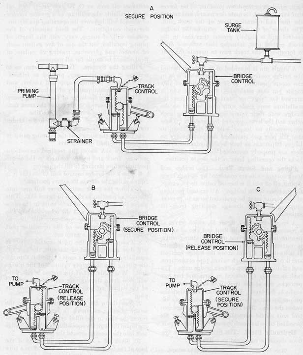
Filling the System. To fill the system or to reprime it when necessary, proceed as follows:
1. Obtain a priming pump and bucket, and prepare a sufficient quantity of hydraulic fluid.
2. Connect the discharge of the priming pump to the pipe connection in the top of the track control unit, installing a strainer in the line.
3. Close the cut-off valve between the bridge control unit and the surge tank.
4. Immerse the suction of the priming pump in the hydraulic fluid in the bucket.
5. Figure 45A shows the required connections with the track and bridge controls in the secure position before starting to fill the system.
6. Check the bridge control unit to see that it is fully against the stop in its secure position.
7. Throw the track control lever full over into the release position as shown in figure 45B. This places the mated rams of both units in the same position, one pair up and the other down. The equalizing ports of the "up" pair will then be uncovered. Remove one of the equalizing port plugs from the bridge control unit.
8. Pump fluid into the track control unit. It will flow into the head of the unit, through the equalizing port, into the empty cylinder, through the piping into the empty cylinder of the bridge unit. When this half of the system is full, fluid will flow from the opening exposed by removal of the equalizing port plug. Then replace the plug.
9. Now throw the track control lever into the secure position as shown in figure 45C. This forces the ram in the filled cylinder down, pushing liquid through the equalizing port in the bridge unit into the housing around the pinion.
10. Slack off a union in the filled line at the base of the track control unit, or ease off on a pipe plug connecting to the filled cylinder.
11. Throw the bridge control lever into its release position, placing the system into the condition shown in figure 45C. Excess fluid will be
46
Figure 45.-Filling Hydraulic Control Mk 1-Schematic Diagram.
47
forced out of the union or pipe plug. Tighten the union or plug.
12. Open the valve connected to the surge tank and check to see that the valve in the other system remains closed.
13. Again pump fluid into the system. Fluid will now fill the empty track control cylinder, and will be forced up into the surge tank. When the surge tank is filled to the desired level, cease pumping.
14. Remove the priming pump. There is now an excess in the portion of the system just filled and a deficiency in the other side.
15. Throw the bridge control lever back into its secure position placing the system again in the condition shown in figure 45A. Excess fluid will be forced through the open equalizing port in the track control unit and into the track control unit housing. At the same time a partial vacuum will be formed in the portion of the system with too little fluid. When the forward ram of the bridge unit reaches its up position and uncovers its equalizing port, fluid will be sucked through the port from the housing and fill the forward portion of the system.
16. Replace the plug in the housing of the track control unit and then work out any air which may be trapped in the system by operating the track and bridge controls alternately, taking care to operate each through a full stroke each time.
As previously noted, there is a slightly greater volume of fluid in the bridge control cylinders than in the track control cylinders, so as to insure full throw of the track control unit. Excess pressure will not be built up in the lines, however, as there is sufficient clearance between the ram heads and the cylinders in the track unit to allow fluid to flow past the leather cup and relieve such pressure.
Local Control Operation. To operate the depth charge release track by local control, the track control unit, only, is employed.
1. Make sure that the securing toggle pin on the bridge control unit is in place. If a toggle pin or other securing device is installed at the track control unit, remove it.
2. Grasp the track control lever and squeeze the grip release, lifting the latch clear of the notch in the track control disc.
3. Operate the lever briskly, in one continuous motion, until it bears against the after stop. This
operates the release detents and releases the after-most depth charge.
4. Hold the lever in the release position until the next charge rests against the forward detents.
5. Operate the lever in the opposite direction, in one continuous motion, until it bears against the forward stop. This returns the detents to their secure position and allows the next depth charge to roll into the release trap.
6. Repeat the above cycle of operation in order to drop each succeeding depth charge.
7. When the dropping operation is completed, return the release lever to its secure position and make sure that the latch is again engaged in the notch in the disc.
Bridge Control Operation. To operate the depth charge release gear remotely, the bridge control unit is employed.
1. If a toggle pin or other securing device is engaged at the track control unit, make sure that it is removed. Also see that the release lever is in the secure position with the lever latch engaged in the. notch of the track control disc.
2. Remove the toggle pin, or lock, from behind the bridge control lever.
3. Operate the bridge control release lever smartly, in one continuous motion, until it bears against the rear stop at the end of the guide arc. This operates the track control unit hydraulically and releases the aftermost depth charge.
4. Hold the lever in the release position for a moment to make sure that the next depth charge rolls into position against the forward track detents.
5. Now operate the lever, in one continuous motion, back to the secure position against the forward stop. This allows the next depth charge to roll into the release trap.
6. Repeat the above cycle of operation in order to drop each succeeding depth charge.
7. When the dropping operation is completed, return the bridge control lever to its secure position, locking it against its stop by replacing the toggle pin.
8. Check the track control unit to see that it also, is in its secure position against the forward stop, and replace whatever locking device may have been in use.
Locking Devices. In order to secure the controls against inadvertent or unauthorized operation,
48
certain locking devices may be installed. On the bridge control unit, the locking toggle pin may be replaced by a padlock inserted through the same two holes, providing a positive lock.
One locking device designed for the track control unit consists of a clevis mounted on the forward stop bolt. The two legs of the clevis pass around the release lever. Matching holes are drilled in the legs of the clevis and a toggle pin is provided to pass through them, thus securing the lever against the stop. The end of the pin may be drilled for the installation of a padlock if this is necessary.
Ships not having such locking devices installed should take steps to procure them where available. Temporarily, operating levers may be lashed in position in order to prevent unauthorized operation. In this case, a knife or hatchet must be kept immediately available for cutting the lashing in case an emergency arises.
Depth Charge Release Control (Electric-Hydraulic) Mk 3 Mod 0
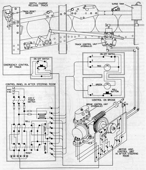
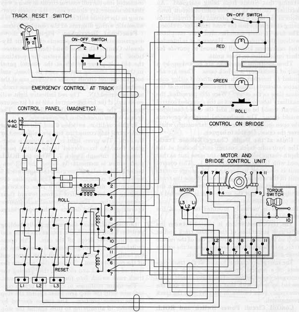
Depth Charge Release Control (Electric-Hydraulic) Mk 3 Mod 0, figure 46, consists of the bridge and track control units of Hydraulic Control Mk 1, a motor to drive the bridge control unit, a cam switching unit also driven by the motor, a control panel ( magnetic) for starting and reversing the motor, and switches and push buttons for energizing and actuating the motor and control circuits.
Advantages. This release control has a number of advantages over Hydraulic Control Mk 1. The motor, hydraulic bridge control unit, cam switching unit and magnetic control panel are all located in the after steering station where they are much less susceptible to battle damage than if located on the bridge. The close proximity of the bridge control unit to the track control unit greatly shortens the length of piping between the two and thus lessens its susceptibility to damage. The push button and switch, which are located on the bridge, occupy little space in comparison with the hydraulic bridge control unit formerly located there. The cycling time obtained with the electric-hydraulic system is shorter and more consistent than that obtained with Hydraulic Control Mk 1.
The automatic torque switch installed with the motor provides other advantages with this unit. This switch cuts out the motor at a predetermined torque output so that it will not continue to drive in the event that a depth charge jams in the track. Improper lubrication or adjustment of the track may impose excessive torque upon the motor. In this case it will cut out and refuse to drive the track control under conditions which may cause damage to the track.
Because of this feature, personnel, in testing the track control, must not assume that failure to operate lies in the control itself, but must investigate the track and its adjustments to make sure that the fault does not lie there.
Description. The various components of Electric Hydraulic Control Mk 3 Mod 0 are located as follows:
In After Steering Station
Drive Unit and Bridge Control Assembly
Control Panel (Magnetic)
At Depth Charge Release Track
Track Control Unit
Track Reset Switch
Control Circuit Power Switch and Emergency Reset Button
On Bridge
Control Circuit Power Switch and ROLL Button
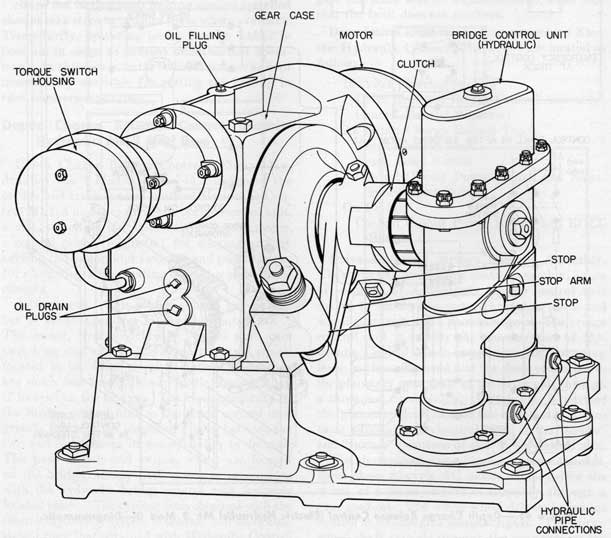
Drive Unit and Bridge Control Assembly. The drive unit and bridge control assembly, figure 47, consists of a hydraulic bridge control unit driven by an electric motor through a worm and wheel gear train and a planetary gear. The bridge control unit is exactly the same as that of Hydraulic Control Mk 1 except that the operating lever has been removed and the shaft connected to the planetary gear shaft of the drive unit through a three-jaw fixed clutch. A stop arm is part of the planetary gear half of the clutch and it contacts adjustable mechanical stops at the "secure" and "release" positions of the bridge control unit.
The electric motor is a 1 1/2-horsepower 440-volt, three-phase 60-cycle AC motor which drives the worm, of a worm and wheel assembly, through a spur gear set. The worm wheel drives the bridge control unit through a planetary gear. The worm, wheel shaft extends through the gear case on the side opposite the bridge control unit and mounts a
49
Figure 46.-Depth Charge Release Control (Electric Hydraulic) Mk 3 Mod 0-Diagrammatic.
50
cam, figure 46. This cam operates switches which are parts of the control circuits.
Another feature of this unit is the torque switch. The worm shaft is extended through the gear case into a cylindrical housing within which is mounted a microswitch. The lever of the microswitch extends into a V-shaped groove cut in the worm shaft. Any lateral displacement of the worm shaft in either direction will move the "V" against the switch lever and open the switch.
The motor, gear case, cam and switch box, torque switch and bridge control unit are all mounted on
a single pedestal, which is normally located in the after steering station.
Control Panel (Magnetic). The control panel, magnetic, contains the main 440-volt power switch, a transformer which supplies 110-volt, single-cycle AC for the control circuits, reversing contactors and their holding relays. The transformer and holding relays are connected to a terminal board within the panel and thereafter to other parts of the system through cabling. The reversing contactors are connected to a separate
Figure 47.-Drive Unit and Bridge Control Assembly.
51
terminal strip and then to the control unit panel and motor by a cable.
The roll and reset contactors are electrically interlocked by means of auxiliary contacts connected into the control circuits. When the roll contactor is closed, the normally closed auxiliary contact in the reset control circuit is opened, preventing that circuit from being energized. An auxiliary contact in the roll control circuit functions, in the same way to prevent that circuit from being energized when the reset contactor is closed. The first 75 units manufactured were completed without these interlocks. However, it is intended that conversion kits will be issued to provide for their installation on these units.
These electrical interlocks are backed up by a pair of mechanical interlock cams. These are adjusted to interfere with each other if either contactor attempts to assume the closed position at the same time as the other. Were this permitted, the auxiliary interlock contact in the energized control circuit would be opened, and the closed contactor would open. The mechanical interlock prevents the open contactor from moving far enough, whatever the cause, for this to happen.
Units at the Depth Charge Release Track. The hydraulic track control unit, located at the depth charge release track, is the same unit as that used with Hydraulic Control Mk 1. This control unit is connected by piping to the bridge control unit in the after steering station. Since the track control unit is now at a higher elevation than the bridge control unit the surge tank is connected to the pipe connection in the top of the track unit. The tank is normally mounted on one of the stanchions of the depth charge track.
The track reset switch is located between the aftermost stanchions of the release track and at such an elevation that, in rolling out of the release trap, each depth charge presses against the switch lever and momentarily closes the switch.
The emergency control located at the track consists of a control circuit power switch and an emergency reset button. The power switch is connected in series with that on the bridge and the emergency reset button, in parallel with the track reset switch.
Control Circuit Power Switch and ROLL Button. These units are normally located on the bridge but may be located at the ASW station
below decks. The power switch box also mounts a red lamp which, when on, indicates that the control circuit power is on. The ROLL button housing mounts a green lamp in addition to the button. When this lamp is on it indicates that the bridge control unit is in the secure position and ready to commence a release cycle. The ROLL button is connected into the roll control circuit in such a way that its momentary closure starts the system operating in the release half of a cycle. Figure 48 is a schematic wiring diagram of the complete system.
Functional Description. Figure 46 shows diagrammatically all components of Electric Hydraulic Control Mk 3 Mod 0 and their interconnections. In order to set up the system for operation, the 440-volt power switch at the control panel in the after steering station must be closed, and both the control circuit power switches, one at the bridge station and the other at the release track, must be turned ON. The red indicator light will go on and, if the bridge control unit is at its secure position, the green light also will go on. The system is then in condition for operation.
In this condition, switches 6 and 7 in the motor and control unit connection box are held closed by the cam. The green light on the bridge is energized from the transformer in the control panel (magnetic) through switch 7. When the ROLL push button is momentarily closed, the roll contactor holding relay is energized through switch 6 and the roll contactor closes. This supplies 440 volts to the drive motor which runs clockwise, stroking the bridge control pistons toward their release position. The track control unit follows, operating the release detents of the depth charge track.
During this period the cam, initially holding switches 6 and 7 closed, also rotates clockwise and the switch lever drops off the cam. This opens switches 6 and 7 extinguishing the green lamp on the bridge and dropping the roll push button out of the control circuit. The cam then contacts the lever of switch 11 and closes it, thus placing the track reset switch into the reset control circuit.
The motor continues to drive the bridge control unit until the stop arm bears against the stop in the release position. The torque exerted by the motor in attempting to turn against the stop causes a longitudinal shift of the worm gear and shaft. This makes the V-shaped groove in the
52
shaft bear against the lever of the torque switch and open switch 10 momentarily. This de-energizes the roll contactor, causing it to open and stop the motor.
The system is now in the release position, switches 6 and 7 open, the ROLL push button disconnected,
switch 11 closed, the track reset switch connected into the control circuit and torque switch 10 closed again. The aftermost depth charge in the depth charge track is rolling out of the release trap.
On its way out of the track the depth charge
Figure 48.-Depth Charge Release Control (Electric-Hydraulic) Mk 3 Mod 0-Schematic Wiring Diagram.
53
presses the operating lever of the track reset switch, momentarily closing it. This energizes, through switch 11, the reset contactor holding relay, closing the reset contactor. This causes the drive motor to run counterclockwise, stroking the bridge control unit back toward its secure position, with the track control unit following.
The cam, also rotating counterclockwise, drops the lever of switch 11. This opens it, and, toward the end of the stroke, picks up the lever of switches 6 and 7, reclosing them. Thus the track reset switch is dropped out. The ROLL push button is placed back into the control circuit and the green lamp again lighted.
At the end of the cycle, when the stop arm strikes against the stop in the secure position, the torque switch is again opened momentarily, the reset contactor opened, and the motor stopped with the system again in its secure position ready to begin another cycle.
Caution: Whenever the system is to be operated all personnel must be cautious to keep clear of the track control unit and the bridge control unit. The release lever and the stop arm both operate at high speed and may cause injury to any part of the body with which they make contact.
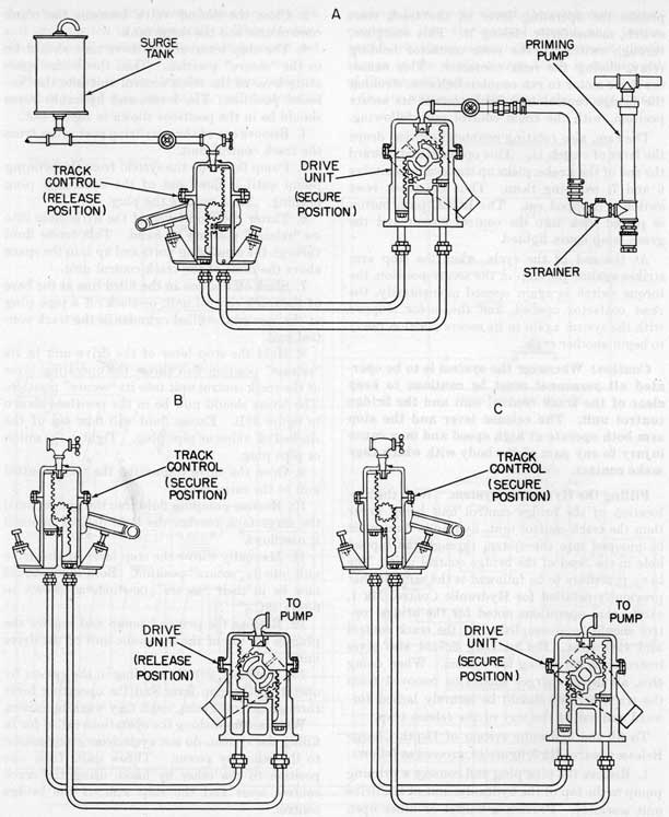
Filling the Hydraulic System. With the new location of the bridge control unit being lower than the track control unit, hydraulic fluid must be pumped into the system through the tapped hole in the head of the bridge control unit. The basic procedure to be followed is the same as that previously detailed for Hydraulic Control Mk 1, except that operations noted for the bridge control should be accomplished at the track control and vice versa. BuOrd Dwg 629454 also gives instructions for filling the system. When doing this, all depth charges should be removed from the track or they should be securely lashed forward and out of the way of the release trap.
To fill the hydraulic system of Depth Charge Release Control Mk 3, figure 49, proceed as follows:
1. Remove the pipe plug and connect a priming pump to the top of the hydraulic unit of the drive unit assembly. Provide a bucket or other open top container with a quantity of hydraulic fluid, and immerse the suction end of the pump in it.
2. Close the cut-off valve between the track control unit and the surge tank.
3. The stop lever of the drive unit should be in the "secure" position. Then throw the operating lever of the track control unit into the "release" position. The levers and hydraulic rams should be in the positions shown in figure 49A.
4. Remove one of the equalizing port plugs from the track control unit.
5. Pump fluid into the system from the priming pump until it flows out of the equalizing plug opening. Then replace the plug.
6. Throw the stop lever of the drive unit into its "release" position by hand. This forces fluid through the equalizing ports and up into the space above the rams of the track control unit.
7. Slack off a union in the filled line at the base of the track control unit, or slack off a pipe plug at the base of the filled cylinder in the track control unit.
8. Hold the stop lever of the drive unit in its "release" position and throw the operating lever of the track control unit into its "secure" position. The levers should now be in the positions shown in figure 49B. Excess fluid will flow out of the slacked off union or pipe plug. Tighten the union or pipe plug.
9. Open the valve connecting the track control unit to the surge tank.
10. Resume pumping fluid into the system until the surge tank reaches the level desired or until it overflows.
11. Manually throw the stop lever of the drive unit into its "secure" position. Both units should now be in their "secure" positions as shown in figure re 49C.
12. Remove the priming pump and replace the plug in the top of the hydraulic unit of the drive unit.
13. Work out any air residing in the system by operating the stop lever and the operating lever through several cycles, until they work in unison.
When accomplishing the operations called for in filling the system, do not cycle from one position to the other by power. Throw units from one position to the other by hand, using the track control lever and the stop arm of the bridge control.
The gear system of the drive unit is designed to run in a bath of oil and may be filled through
54
Figure 49.-Filling Depth Charge Release Control Mk 3.
55
a plug in the top of the gear case. SAE 6 lubricating oil should be used and the case should be filled to the level indicated on BuOrd Dwg 561821 Sheet 1.
Testing. Depth Charge Release Control (Electric-Hydraulic) Mk 3 Mod 0 should be tested after installation and weekly thereafter as follows:
1. Either remove all depth charges from the track to be tested, or lash them securely well forward of the track release trap.
Caution: Have all personnel stand clear of both the track control and bridge control units in order to prevent injury by the release lever or stop arm.
2. Check the oil level in the drive unit gear case and refill as necessary.
3. Check to see if the hydraulic system is properly filled as follows:
(a) Make sure that the track control lever latch is engaged in the control disc.
(b) Manually stroke the track control lever between the secure and release positions several times, noting each time whether the bridge control unit follows hydraulically and the stop arm engages the stop at each position.
(c) If the stop arm misses the stop in either or both positions by more than a small amount, this is an indication that the system is improperly filled.
(d) If the stop arm misses the stop by only a small amount, the stops should be readjusted until the arm makes full contact at each position.
(e) Return the system to the secure position.
4. Having checked the hydraulic system, turn the ON-OFF switches at both the bridge station and release track to ON. The red lamp at the bridge station should go on, and if the system is properly in the secure position, the green lamp should also light.
5. Push the ROLL button at the bridge station. The track control unit should stroke smartly from the secure to the release position and stop. The green lamp at the bridge .station should go out.
6. Manually operate the track reset switch by pressing on the switch lever. The track control unit should return smartly to its secure position and the green lamp at the bridge station should go on.
7. Close the track reset switch manually and hold it closed during the following operation.
8. Press the ROLL button at the bridge station. The track control unit should stroke to the release position and immediately return to the secure, position.
9. Repeat step 8 several times, noting with a stop watch the time required to complete each cycle. This time should be between 1.3 and 1.8 seconds.
10. Check operation of the torque switch by holding the track control lever down when the ROLL button is pushed. The track control lever should attempt to start into motion, but should immediately stop as the torque switch operates to cut off power from the motor.
11. Repeat step 10 but allow the track control lever to start moving, then gradually bring it to a stop. The torque switch should again cut off power from the motor.
12. Return the system to its secure position by pressing the emergency reset switch at the track.
13. Repeat steps 11 and 12 several times. The drive motor should never stall with power on. The torque switch should always cut off the power.
14. Test the track and control operation with a dummy depth charge or an empty case. Release the charge several times by pressing the ROLL button. The charge should be allowed to roll completely off the track, closing the track reset switch on the way, and the track control unit should stroke smoothly to its release position and return immediately to secure.
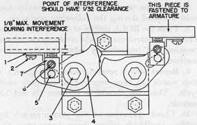
Adjusting Contactor Interlock Cams. The interlock cants in the control panel (magnetic) must be carefully adjusted in order to function properly. Figure 50 shows the arrangement of the cams. Adjustment should be made as follows:
1. Check interference of the cams by holding the armature of one contactor up in the closed position. Then move up the armature of the other contactor. The cams should interfere with each other and not permit the second armature to move more than one-eighth-inch from its original open position.
2. If the permitted movement is greater than the specified amount, adjustment of the cam on the second contactor is indicated. Adjust in accordance with the following steps.
3. Remove angle piece 1 by taking out screw 2.
56
Figure 50.-Mechanical Interlock Cams in Control
Panel (Magnetic).
4. Remove screw 3, then lift off cam 4 and take out pin 5.
5. Back off screw 6 and then turn piece 7 clockwise screwing it upwards. This will decrease the permitted amount of travel of the contactor being adjusted.
6. Replace pin 5 and cam 4 and check the permitted travel of the armature.
7. Repeat steps 4, 5, and 6 as necessary until the permitted travel is within the required limits, then replace and secure all parts previously removed or loosened.
8. After setting one cam, adjust the other following the same procedure.
Depth Charge Release Control (Electric-Hydraulic) Mk 2 Mod 0
Six experimental units of Electric-Hydraulic Control Mk 2, figure 51, were installed for service test on destroyer escort vessels. All of these vessels are now in reserve status and no further installations of this control will be made. The following description of the control and its functioning is included here merely for information, and to show the steps through which the development of electric hydraulic controls has passed.
This control uses the track control unit of Hydraulic Control Mk 1. It is actuated by hydraulic power delivered from an electrically driven oil motor. Oil pressure is transmitted to the rams of the track control unit through a double solenoid operated valve. This valve channels pressure to the proper ram to drive the unit as required into the release or secure position.
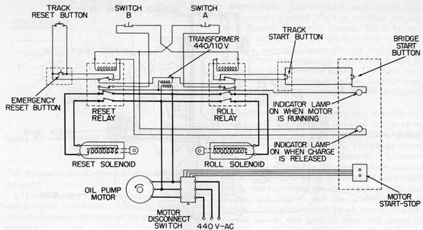
Description. The standard track control unit of Hydraulic Control Mk 1 is modified for use with Electric Hydraulic Control Mk 2 by replacing each of the Stop brackets with a switch and stop assembly, figure 51. In this text the switches will be designated as switches A and B and are so labelled in the figure. The track control unit is mounted inboard of the depth charge release track in the same manner as for Hydraulic Control Mk 1.
The electric motor, oil pump and solenoid operated valve are normally installed in the after steering station and are connected by 3/4-inch piping to the track control unit. The piping is run as schematically shown in figure 51. A motor controller is installed in the after steering station, and a relay control panel is located at the bridge depth charge release station, together with the bridge start button and the motor start-stop button. The relay control panel mounts two indicator lamps: One goes on when the motor is running and the other flashes when a depth charge rolls off the track.
In addition to switches A and B on the track control unit there is a track reset switch installed between the tracks outboard of the release trap, and an emergency reset button and start button mounted on the inboard side of the track structure.
Functional Description. Depth Charge Release Control (Electric-Hydraulic) Mk 2 operates in the following manner.
Assuming the track control unit to be in its secure position, the system is prepared for operation by closing the motor disconnect switch on the motor control panel and then pushing the motor start push button, figure 52. This will start the motor and oil pump, and oil pressure will be delivered to the hydraulic valve. The motor indicator lamp will stay lighted while the motor is running. Neither solenoid is energized, therefore the valve lies in its neutral position, figure 51. In this condition the oil enters the hollow core of the valve through the central port and drains out of the end ports back into the sump tank.
To cycle the track control unit the start push button is closed momentarily, energizing the roll relay, figure 52, closing three normally open contacts and opening one normally closed contact. One of the contacts now closed is in parallel with the start button and so acts as a holding contact to
57
Figure 51.-Depth Charge Release Control (Electric-Hydraulic) Mk 2 Mod 0-Hydraulic Diagram.
58
Figure 52.-Depth Charge Release Control (Electric-Hydraulic) Mk 2 Mod 0-Schematic Wiring Diagram.
keep the relay coil energized. The other two closed contacts energize the roll solenoid of the hydraulic valve. The relay contact now open is connected in series with the reset relay coil and prevents it from being energized while the roll relay is closed.
The roll solenoid draws the hydraulic valve to the right and causes oil pressure to be delivered to the right hand ram of the track control unit.
A tapered plug is mounted at the base of each ram, figure 51, extending down into the pipe connection and closing off the bottom connection when the ram is in its down position. To reach the ram, the oil passes through a bypass and check valve to the side connection from which it gets behind the ram and forces it up, driving the track control into its release position.
As the track control unit reaches its release position, the lever presses against the arm of switch
B and opens the switch. This de-energizes the roll relay.
The operation of the track control in turn operates the track release detents and releases the depth charge in the release trap. As the charge rolls out of the trap, it passes over the treadle of
the track reset switch and momentarily closes it. This energizes the reset relay, which, in turn, energizes the reset solenoid and opens the contact connected in series with the roll relay coil. It also lights the indicator lamp to show that a charge has been released.
The reset solenoid, when energized, draws the spool of the hydraulic valve to the left and causes oil pressure to be delivered to the left hand ram of the track control unit. This drives the unit back to its secure position. As it reaches that position, its lever opens switch A, thus de-energizing the reset relay. The system is now in the same condition as it was before the start button was pressed.
To cycle the system to release each depth charge, it is necessary only to press the start button momentarily. If the motor disconnect switch and the motor start button have been closed, the system will then operate through a complete cycle without any further operation.
The start button located at the depth charge track is connected in parallel with the start button at the bridge station and, therefore, permits the system to be cycled for test purposes, or, in the
59
event it is necessary to drop charges, from the track station. The emergency reset button located at the track is connected in parallel with the track reset switch and may be used to return the system to secure, in the event a depth charge has jammed in the release trap, or for test purposes.
Caution: Whenever the system is operated, all personnel must be cautioned to stand clear of the track control unit. The lever operates at high speed and may cause injury.
Special Features. As noted above, each relay contains a pair of contacts which are connected in series with the coil of the opposite relay, so that it is impossible for both relays to become energized at the same time. In addition to this, the relays are fitted with mechanical interlocks of the interference type described in connection with Electric Hydraulic Control Mk 3.
The tapered plug mounted at the base of each
ram in the track control unit provides a cushioning effect at the bottom of the ram's travel. This cushioning effect is necessary since, otherwise, the rams, traveling at such high speed, would strike the bottom of the cylinder with quite a shock. As the ram nears the bottom of the cylinder, the plug enters the pipe and closes it off, except for the annular space surrounding the plug. As the ram travels further down, the annular space narrows due to the taper of the plug and finally closes off entirely. This diminishing area for the passage of the oil causes the cushioning effect desired. When it is necessary to deliver oil to the ram, however, this connection cannot be used until the ram has been started upward and the plug withdrawn from the pipe. For this purpose the bypass is provided and oil is routed through the side connection. The check valve in the bypass closes off this route during the down stroke of the ram, forcing all the oil to pass through the bottom connection
60
Chapter 8 GENERAL MAINTENANCE INSTRUCTIONS AND HANDLING OF DEPTH CHARGES
General Maintenance of Tracks and Equipment
Depth charge release tracks and their associated equipment require little besides routine maintenance in order to keep them in good operating condition. One of the more important items of maintenance is keeping the tracks and guide rails clean and free of foreign materials in order to prevent possible jamming of depth charges. Pawls and detents also must be kept scrupulously clean and operating freely. The following inspection and maintenance should be accomplished weekly ( oftener in cold weather) in order to insure that tracks are in constant operating condition.
1. Clean all foreign substances from track, guide rails, and depth charges. Because the clearance provided between tracks and charges is quite small, even a minor amount of dirt may cause jamming of a charge.
2. If Depth Charge Mk 9 is used, check their end rings for damage or distortion. Remove any charges that indicate such distortion and set them aside for projection rather than dropping.
3. In cold weather, make sure that all ice or frost is removed from the track and its operating parts. Use hot water or a steam lance in the event de-icing equipment has not yet been installed.
4. Check all bearings and moving parts to see that they operate freely, that all bearing surfaces are free of paint and foreign matter, and that they are well lubricated. In lubricating, refer to the lubrication charts found in earlier chapters of this pamphlet, or obtained from the Naval Gun Factory. If desired, photoprint reproductions of lubrication charts may be ordered from the Gun Factory for use as check-off lists.
5. Check for tightness, all bolts in track, track foundation and release controls.
6. Keep all painted areas wire brushed free of corrosion and well painted to guard against rusting.
7. If a hydraulic release control is installed, check all hydraulic piping for tightness. A hydrostatic test at 500 psi should be applied monthly in order to discover points of weakness in the hydraulic system.
8. Check the packing around the shafts of control units for tightness. Take up glands or renew packing as found necessary.
9. Operate the release system through several cycles in order to check its operation. Make sure that the release trap is empty and that other charges are securely lashed forward of the trap before making this test.
10. Check the wiping plate alignment, making sure that the clearances are in accordance with figure 8. If the plates are out of alignment, they may either jam a charge or fail to remove a safety fork.
Handling Depth Charges
Extreme care must be taken in handling depth charges while loading them into release tracks. Shipping safety forks and covers, without knobs, should always be in place when handling charges in order to prevent accidental arming of the charges. Knobbed safety forks and covers should be installed after the charges have been loaded and are finally at rest in the track.
Normally, a davit is stepped at the forward end of the track for use when lifting charges into the track. Charges should be loaded with the pistols on the most convenient side for inspection and setting. With most installations this will be the inboard side. Track Mk 9 accommodates British charges as well as United States charges. These must be loaded so that their pistols are on the same side of the track as the track control. The pistol of the British Depth Charge Mk 7 (heavy) is in the end to which the weight is attached.
While handling depth charges, pistols should be set on SAFE. If a ship is in danger of sinking,
61
every effort should be made to set pistols on SAFE before abandoning ship, even if safety covers and forks are installed.
Frequently, insufficient space is available for stepping davits and other means must be provided for handling charges. Often wooden ramps are used and the charges parbuckled up to the open mouth of the track, although in many cases they have to be manhandled. The installation of the loading trays previously described will be of great assistance in this event. These trays are not standard equipment and therefore will not be provided with the tracks. They are, however, authorized for installation at the request of the commanding officer, when ship availability at a naval shipyard permits.
When loading depth charges they should always be kept under control and not allowed to roll freely down a track where they- may strike with force other charges, detents or pawls.
When charges are not held in readiness for release they should always be lashed to the track to prevent them from rolling fore-and-aft and causing damage to the track or other charges. This is often done by the use of timbers lashed forward of the forwardmost charge and aft of the aftermost charge, usually with the release trap empty. However, safety and stop bars are now authorized for installation at both ends of the traps making timbers unnecessary. Stop and safety bars are described in earlier chapters of this pamphlet.
62
APPENDIX A REFERENCE PUBLICATIONS
The publications listed here provide information which may be of value to personnel charged with operation and maintenance of depth charge release tracks and associated equipment. See appendix B for supplementary information and instructions:
NAVORD Ordalt 1898-Depth Charge Release Track Mk 7 and Track Extension Mk 7 Mods 0, 1; Modification of Lower Rails.
NAVORD Ordalt 1993-Depth Charge Release Gear Types C and D; Modification of Release Mechanism Fulcrum Pins.
NAVORD Ordalt 2069-Depth Charge Release Track Mk 9 Mod 0 ; Conversion to Depth Charge Release Track Mk 9 Mod 2.
NAVORD Ordalt 2139-Depth Charge Release Tracks Mk 1 Mods 0, 1; Modification to Increase Accessibility to After Depth Charges and to Reduce Depth Charge Jamming.
NAVORD Ordalt 2203-Depth Charge Release Tracks Mk 1 Mods 0, 1; Mk 3 Mod 0 ; Mk 9 Mods 0-3 ; Modification of the Outboard Wiping Plate.
NAVORD Ordalt 2238-Depth Charge Release Tracks Mk 3 Mod 0; Modification to Increase Accessibility to After Depth Charge.
NAVORD Ordalt 2833-Depth Charge Release Track Mk 3 Mod 1. Conversion to Depth Charge Release Track Mk 3 Mod 2.
NAVORD Ordalt 2994-Depth Charge Release Track Mk 9 Mod 2. Conversion to Depth Charge Release Track Mk 9 Mod 5.
NAVORD Ordalt 3094-Depth Charge Release Track Mk 3 Mod 0 ; Conversion to Depth Charge Release Track Mk 3 Mod 2.
NAVORD OS 926-Specifications for Installation and Test of Depth Charge Release Track Mk 3 with Hydraulic Control Mk 1.
NAVORD OS 2274-Installation and Test Depth Charge Release Tracks Mk 6 with Hydraulic Control Mk 1 or Local Control Mk 1.
NAVORD OS 2446-Installation and Test of Depth Charge Release Track Mk 41 With Hydraulic Control Mk 1 or Local Control Mk 1.
NAVORD OS 2447-Installation and Test of Depth Charge Release Tracks Mk 5 with Hydraulic Control Mk 1 or Local Control Mk 1.1
NAVORD OS 2449-Installation and Test of Depth Charge Release Track Mk 7 ( with local control only) and Track Extension Mk 7.
NAVORD OS 2494-Installation, Adjustment and Test of Depth Charge Release Tracks Mk 9 and Mk 9 Mods 1, 2, 3, and 4 With Hydraulic Control Mk 1.
NAVORD OS 2622-Installation and Test of Depth Charge Release Tracks Type C and Type D.