|
Folks,
Depth Charge Projector Mark 6, Mod 1 and Mod 2, OP 831, 1944, covers the "K" gun depth charge projector.
We thank Ed Zajkowski for his generous loan of the original document used to create this online version.
Please report any problems with the Mail Feedback Form for correction.
Richard Pekelney
Webmaster
|
|
|
|
1
|
RESTRICTED |
ORDNANCE PAMPHLET No. 747 |
(FIRST REVISION)
DEPTH CHARGE
PROJECTOR MARK 6
MOD 1 and MOD 2

21 JULY 1944
This publication is RESTRICTED and will be handled in accordance with Article 76 United States Navy Regulations 1920
UNITED STATES GOVERNMENT PRINTING OFFICE
WASHINGTON 1944
|
2
|
|
NAVY DEPARTMENT
BUREAU OF ORDNANCE
WASHINGTON, D. C.
ORDNANCE PAMPHLET 831 (FIRST REVISION)
DEPTH CHARGE PROJECTOR MARK 6 MOD 1 AND MOD 2
1. Ordnance Pamphlet 831 (First Revision) describes the Depth Charge Projector Mark 6 Mod 1 and Mod 2 and gives instructions for its use and maintenance. This projector takes the place of the older "Y" gun type projector.
2. This pamphlet is issued for reference to all personnel concerned with the operation of the projector. The tactical use of this projector is outside the scope of this publication and is covered in publications from other sources.
3. This pamphlet supersedes Ordnance Pamphlet 831 and Ordnance Circular Letter M24-43, which should be destroyed. Reference should be made to the following existing publications: Ordnance Pamphlet 747 (First Revision), "Depth Charges Mark 6, Mark 6 Mod 1, Mark 7, and Mark 7 Mod 1-Operating and Maintenance Instructions"; Ordnance Pamphlet 866 (First Revision), "Depth Charge Mark 9 and Modifications-Description and Instructions for use"; ORD 662(A) and FTP 223 of higher classification; NAVORD ORDALT 1221, "Depth Charge Projector Mark 6-Instructions for Converting to Depth Charge Projector Mark 6 Mod 1"; NAVORD ORDALT 1963, "Depth Charge Projector Mark 6 Mod 1-Instructions for Removing the Breech Buffer Stop"; Ordnance Data 5318, "Preparation of Impulse Cartridges for Single Depth Charge Projector Mark 6"; Ordnance Specification 3057, "Installation of Depth Charge Projector Breech Cover Mark 2."
4. This publication is RESTRICTED and should be handled in accordance with Article 76, U. S. Navy Regulations, 1920.
G. F. HUSSEY, JR.
Rear Admiral, U. S. Navy
Chief of the Bureau of Ordnance

Acting.
|
|
3
|
CONTENTS
| INTRODUCTION: |
| WHAT THEY ARE-THEIR PURPOSE-WHERE THEY ARE USED |
4 |
| GENERAL DESCRIPTION: |
| BASE |
6 |
| BARREL |
6 |
| BREECH |
7 |
| BREECH COVER |
7 |
| CARTRIDGES |
8 |
| ARBOR |
8 |
| DEPTH CHARGE |
9 |
| OPERATION: |
| LOADING ARBORS AND DEPTH CHARGES |
10 |
| OPENING AND CLOSING BREECH |
12 |
| LOADING CARTRIDGES |
12 |
| FIRING PROCEDURE |
14 |
| SAFETY PRECAUTIONS |
14 |
| MAINTENANCE: |
| GENERAL MAINTENANCE |
15 |
| ELECTRICAL MAINTENANCE |
15 |
| DISASSEMBLY OF BREECH MECHANISM |
17 |
| DISASSEMBLY OF FIRING PIN MECHANISM |
18 |
| DISASSEMBLY OF SEAR BRACKET MECHANISM |
19 |
| SAFETY PRECAUTIONS |
20 |
| SUPPLY |
20 |
| DISTRIBUTION |
Inside Back Cover |
|
4
|
|
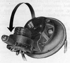
Figure 1.-Depth Charge Projector Mark 6 Mod 1 or Mod 2, Loaded.
|
|
WHAT THEY ARE
Depth Charge Projectors Mk 6 Mod 1 and Mod 2 are weapons for projecting depth charges. The projectors consist of a base with an expansion chamber and two tubular extensions, one serving as a mount for the steel barrel of the projector, and the other serving as a cartridge chamber with a breech mechanism mounted thereon.
THEIR PURPOSE
The primary purpose of these weapons is to project depth charges to port and starboard of vessels in order to enlarge and supplement the pattern obtained by charges dropped from the stern.
|
|
HOW THEY WORK
When the propellant charge in the cartridge case chamber is fired, either electrically or percussively, the arbor with a depth charge secured to it is forced from the projector barrel. The arbors are mechanically released from the depth charges, and the two fall into the sea independently.
WHERE THEY ARE USED
The Depth Charge Projectors Mk 6 Mods 1 and 2 are used aboard destroyers, destroyer escorts, submarine chasers, minesweepers, patrol vessels, and other types of craft which may be engaged in action against enemy submarines. The projectors are generally mounted on the port and starboard sides of the after portion of the vessel.
|
5
|
|
GENERAL DESCRIPTION
Size and Weight of the Depth Charge Projector Mk 6 Mod 1 and Mod 2
| Weight (Unloaded) |
328 lb. |
| Base Frame (Diameter) |
20 in. |
| Barrel (Inside Diameter) |
6 in |
| Barrel (Length) |
(approx.) 24 in. |
| Expansion Chamber (Inside Diameter) |
10.5 in. |
| Cartridge Case (Diameter) |
3.0 in |
| Cartridge Case (Length) |
9.0 in |
MAIN PARTS
The main parts of the Depth Charge Projectors Mk 6 Mods 1 and 2 are:
The projector body, including barrel and chamber
The breech mechanism
|
Accessories include:
Impulse cartridge
Arbor
Depth charge
Breech cover Mk 2 |
|
|
OPERATION-GENERAL
Since the Projectors Mk 6 Mods 1 and 2 operate similarly, information hereafter will be applicable to both Mods unless otherwise indicated.
An impulse cartridge is fired in the expansion chamber either electrically from a remote control station or by percussion through manipulation of a lanyard at the mount. Expanding gases from the propellant charge force the arbor with the depth charge attached out of the barrel of the projector. As the depth charge and arbor are shot out, a mechanical release is tripped, freeing the chain or cable which holds the charge to the arbor.
Because of initial velocity, the arbor and the depth charge remain along the same trajectory for approximately three-fourths of the entire flight. The arbor falls into the sea about fifteen or twenty yards short of the range at which the depth charge sinks to explode at its predetermined setting.
|
Figure 2.-Depth Charge and Arbor in Flight.
|
6
|
|
Figure 3.-Depth Charge Projector Mark 6 Mod 1 or Mod 2.
|
|
PROJECTOR BASE, BARREL, AND BREECH
BASE
The projector base consists of a steel casting formed with a 20-inch base flange, drilled for bolting to the deck; a spherical expansion chamber, 10.5 inches in diameter, with two tubular extensions pointing 45° upward and at an angle of 90° to each other. One of these tubular extensions has a steel barrel welded into it, and the other serves as the cartridge chamber topped by a flange for mounting the breech mechanism.
|
|
BARREL
The barrel is a smooth-bore steel tube approximately 24 inches long and has an inside diameter of 6 inches. Two sea lashing hooks are welded to the barrel near its muzzle and directly in line with two notches that are cut in the muzzle. These sea lashing hooks are used to tie the depth charge and arbor to the projector so that heavy seas cannot wash them overboard. The two muzzle notches keep the arbor and attached charge from rotating in the projector barrel.
|
7
|
|
BREECH
The main parts of the breech mechanism are breech ring, breech carrier, breech plug, operating lever, firing pin mechanism, sear bracket, and cartridge extractor.
The breech mechanism is an interrupted screw type requiring a 90° rotation of the operating handle to lock the breech plug in either the opened or the closed position. The firing mechanism is constructed for firing either by percussion or by electricity. The firing pin mechanism is purposely designed so that the firing pin is grounded to the breech plug when the breech is closed, not only for simplicity of design, but in order to prevent any accidental discharges of live cartridges inadvertently left in the chamber. When the breech is opened, the firing pin travels one quarter of an inch from the center of the cartridge primer, and the safety rocker retracts the point of the firing pin beyond the surface of the plug, rendering the breech safe from accidental firing either electrically or percussively when the breech is unlocked. The extractor, operated by a cam integral with the carrier, raises the cartridge from its seat when the breech is opened.
BREECH COVER MARK 2
Breech Cover Mk 2 is a metal breech cover provided to protect the breech mechanism from damage due to water or the formation of ice or accidental discharge from shock. The breech cover should be kept in place at all times except when firing or servicing the projector.
The Depth Charge Projector Mk 6 Mod 2 was originally designed for installation of the Breech Cover Mk 2 according to directions in Ordnance Specification No. 3057. Ordalt No. 1963 gives instructions for removal of the breech buffer stops from those models of the Mod 1 which still have the stops, so that the Breech Cover Mk 2 can also be installed on it.
|
|
Figure 4.-Sections through Breech, Expansion
Chamber, and Barrel.
|
8
|
Figure 5.-Arbor, Depth Charge, and Cartridge.
|
|
IMPULSE CARTRIDGES, ARBORS, AND
DEPTH CHARGES
IMPULSE CARTRIDGES
Impulse cartridges are available with three impulse charges designated No. 1, No. 2, and No. 3. Their use is covered in Ordnance Data 5318 and in FTP 223, to which reference should be made. Note: Discharged cartridge cases are to be saved for reloading with new primers and impulse charges.
ARBORS
Several types of arbors (Arbors Mk 6, Mk 7, and Mk 7 Mod 1) fit these projectors and are used to hold depth charges centered and balanced on the projector to insure uniform trajectories and to protect projector barrels from undue strain.
All of these arbors are primarily the same. Each consists of a tubular stem (24 inches long by 6 inches in diameter), closed on one end and with a tray (12 by 31 inches) welded to the open end. The stem fits into the projector barrel and acts as a projectile when fired. The arbor weights are: Mk 6, 70 pounds; Mk 7 and Mk 7 Mod 1, each 65 pounds.
A depth charge is secured to the arbor tray by means of a chain or wire cable, operating through a tightening device. Incorporated in the arbors is an automatic unlocking device which releases the arbor from the depth charge during flight, thus giving a better underwater trajectory to a sinking depth charge.
|
9
|
|
DEPTH CHARGES
For detailed information about depth charges, reference should be made to Ordnance Pamphlets 747 (First Revision) and 866 (First Revision) and to ORD 662 (A).
CORRECT POSITIONING OF DEPTH CHARGES ON ARBORS
Projection of a depth charge requires the use of an arbor which fits into the barrel of the projector and which places the combined center of gravity of the depth charge and its arbor approximately in line with the axis of the projector barrel. This is necessary in order to minimize stresses upon the projector and to insure that the depth charge is projected in the intended direction.
Depth charge arbors are provided with movable stops on the arbor trays to permit their use with more than a single type of depth charge. It is important that this movable stop be correctly placed for the depth charge being used, and that the depth charge be correctly positioned if it is a weighted charge.
When a Depth Charge Mk 6 (or a British Mk 7) is secured to a Depth Charge Arbor Mk 6, Mk 7, or Mk 7 Mod 1, the -movable stop should be placed on the long side of the arbor tray. Either end of the depth charge may be placed against this stop.
605357°-44--2 |
|
When a Depth Charge Mk 8 (weighted charge) is secured to a Depth Charge Arbor Mk 6, Mk 7, or Mk 7 Mod 1, the movable stop should be placed on the short side of the arbor tray. The heavy end (end filled with cast lead) of the depth charge should be placed against the movable stop.
When a Depth Charge Mk 9 or Mk 9 Mod 1 is secured to a Depth Charge Arbor Mk 7 or Mk 7 Mod 1, the movable stop should be placed on the long side of the arbor tray. Either end of the depth charge may be placed against this stop.
When a Depth Charge Mk 9 Mod 2 or Mk 9 Mod 3 (weighted charges) is secured to a Depth Charge Arbor Mk 7 or Mk 7 Mod 1, the movable stop should be placed on the short side of the arbor tray. The heavy or weighted end (nose end) of the depth charge should be placed against the movable stop.
Stenciled markings indicate the weighted ends of depth charges unless they have been repainted aboard ship.
When a British Depth Charge Mk 7 (Heavy) is secured to a Depth Charge Arbor Mk 6, Mk 7, or Mk 7 Mod 1, the movable stop should be placed on the short side of the arbor tray. The weighted end of the charge should be placed against the movable stop.]
The foregoing information is given below in tabular form for convenient reference.
|
10
|
| DEPTH CHARGE |
ARBOR |
POSITION OF
MOVABLE STOP
ON ARBOR TRAY |
POSITION OF CHARGE IN RELATION TO MOVABLE STOP |
Mk 6 or British
Mk 7 |
Mk 6, Mk 7
Mk 7 Mod 1 |
On Long Side |
Either end of charge against the stop |
| Mk 8* |
Mk 6, Mk 7
Mk 7 Mod 1 |
On Short Side |
Weighted end of charge against the stop |
Mk 9 or Mk 9
Mod 1 |
Mk 7, Mk 7
Mod 1 |
On Long Side |
Either end of charge against the stop |
Mk 9 Mod 2*
Mk 9 Mod 3 |
Mk 7, Mk 7
Mod 1 |
On Short Side |
Weighted end (Nose end) against the stop |
British*
Mk 7 (Heavy) |
Mk 6, Mk 7
Mk 7 Mod 1 |
On Short Side |
Weighted end against the stop |
*Weighted charges on which weighted ends are usually marked by stencilling.
|
|
It will be noted that the arbors and depth charges are used in interchangeable combination, except that the Depth Charges Mk 9 and Mods may be used only with Arbors Mk 7 and Mk 7 Mod 1.
LOADING PROJECTORS WITH ARBORS AND DEPTH CHARGES
The following steps are necessary before inserting an arbor into a projector barrel:
1. Remove drain plug.
2. Open breech mechanism.
3. Clean and lubricate projector barrel.
4. Clean and lubricate arbor stem.
|
LOADING
There are two methods of loading depth charges depending upon the installation
|
|
provided: (1) roller loader and (2) the candlestick or davit loader.
Of the seven possible operations performed in loading, only the first two differ, depending upon which of the aforementioned methods is used. The first two steps are, therefore, listed separately for the respective methods of loading. Steps three through seven are equally applicable to both methods.
ROLLER LOADING
To load from a roller loader:
1. Apply bearing grease (OS No. 1350) to the arbor stem and insert the arbor into the barrel. See that the arbor key rests firmly in the muzzle notch and that the chain or wire tightener is on the upper side of the barrel to facilitate tightening.
|
11
|
|
2. Slide a charge from the loader tray to the arbor tray and secure the charge to the tray by means of the chain or wire tightener.
CANDLESTICK OR DAVIT LOADING
To load from this type loader:
1. Use the davit provided to pick up the charge (with arbor attached) from the candlestick holders and then swing the arbor and charge into proper position for inserting into the barrel of the projector.
2. Apply bearing grease (OS No. 1350) to the arbor stem and insert the arbor stem into the barrel of the projector and carefully lower the arbor and charge until the arbor key rests firmly in the muzzle notch.
THE FOLLOWING STEPS APPLY TO BOTH METHODS OF LOADING:
3. Lash the charge to the sea lashing hooks on the projector, using not over three turns of spun yarn or five turns of Navy marlin. Lashing will be necessary only when it is desired to have projectors loaded and ready for immediate action over long periods and in heavy seas. It prevents charges from being washed overboard, without interfering with firing, since the lashings break when the projector is fired.
4. Insert the arbor releasing chain through a sea lashing hook.
5. Replace the drain plug after loading is completed, if time permits.
|
|
No serious harm will result if the drain plug is not replaced, for the reduction in range is only two or three percent.
During frequent firings it is well to leave the drain plug out, so that slushing can be accomplished more quickly.
6. Insert an impulse cartridge in the breech chamber; then close and lock the breech block.
Steps for opening and closing of the breech mechanism are detailed and illustrated on the next page.
7. Connect the firing lanyard or the electric cable, depending upon the type of firing equipment used.
The projector is then ready to fire.
OPENING AND CLOSING THE COVER
To open:
(a) Loosen the breech cover securing screw and swing the bail up or down until it rests against the projector body.
(b) Lift the cover off the breech mechanism.
To close:
Reverse this procedure.
See that the cover fits its gasket and that the bail is securely fastened. The cover can be replaced only when the breech carrier is in its closed and locked position.
|
12
|
Figure 6.-Operations for Opening the Breech.
|
|
OPENING AND CLOSING THE BREECH
To open:
(a) Pull the operating handle out as far as it will go and swing it counter-clockwise (90°) until it stops.
(b) Lock the handle in the carriage counter-bore and then lift to open the breech.
To close:
Reverse this action.
See that the operating handle is locked in the carrier counterbore after it has been turned to the right.
INSERTING AND REMOVING CARTRIDGES
To insert:
(a) Place the cartridge in the opened breech chamber and gently push until the cartridge flange rests upon the raised extractor.
(b) Close and lock the breech.
|
13
|
|
To remove an empty cartridge or an unexploded one:
Open the breech and remove the raised cartridge by hand.
Note: Discharged cartridge cases are to be saved for reloading with new primers and impulse charges.
Since the firing panel is usually located at a central control station or on the bridge, communication or signal facilities must be maintained with projectors so that in the event of failure to fire electrically, the charge can be fired immediately by percussion.
Electrical firing demands an unfailing source of alternating or direct current wired through the firing switches and to each projector.
Wiring consists of:
(a) Where alternating current is used, two wires ungrounded with the circuit fused for each projector and also a transformer of 15 to 20 volts for each projector.
(b) Where direct current is used, 6 to 21 volt batteries unfused with one side grounded and one wire not grounded.
CONDITION OF READINESS FOR DEPTH CHARGE IN PROJECTORS
1. Complete depth charge assemblies, with pistols, detonators, and booster extender installed.
2. Inlet valve cover removed.
3. Plain safety forks in place on booster extender, with one foot of chain or manila lanyard attached for removal by hand. Lanyard attached only to safety fork.
4. Depth charge to be fastened firmly in arbor by the arbor chain or wire and marlin
|
|
or spun yarn lashing. Lashing need not be used if depth charge projector has just been loaded for immediate use.
5. Depth setting made as prescribed by commanding officer.
Note: Since the projectors are fixed upon the deck, no correction can be made for ship's roll. It is, therefore, important To FIRE ONLY WHEN THE SHIP ROLLS ONTO AN EVEN KEEL.
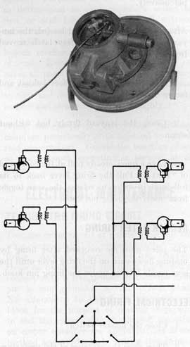
Figure 7.-Percussion and Electric Firing.
|
14
|
|
FIRING PROCEDURE
There are two methods of firing, depending upon the equipment provided: firing lanyard for percussion firing or electric cable for electrical firing.
PERCUSSION FIRING
KEEP THE SAFETY LATCH IN ITS FORWARD OR SAFE POSITION UNTIL READY TO FIRE. The safety latch in this position prevents the lever from being pulled and firing the gun percussively.
After the projector has been loaded, the lanyard attached and the safety latch moved from its safe position:
1. Take position about 8 feet behind and facing the breech.
2. Grasp the lanyard firmly but without strain.
3. Give a quick steady pull at the command of "FIRE." Pull the firing lever back to its full limit in order to release the sear toggle from under the firing pin knob.
RECOCK AFTER FIRING
The piece must be recocked after firing by pushing downward on the firing lever until the sear toggle latches under the firing pin knob.
ELECTRICAL FIRING
1. Close the master switch.
2. Then close the switches of the projectors to be fired.
|
|
SAFETY PRECAUTIONS
1. See that the breech is open before loading an arbor and depth charge.
2. See that the applicable condition below exists until the breech is closed and locked:
(a) The firing key or switch is open at the control station, or
(b) The firing cable at the firing pin is disconnected.
3. Do not keep a cartridge in the breech chamber except when in a danger zone. It. can be loaded in ten seconds.
4. Keep the charge and arbor lashed to the sea lashing hooks' unless immediate firing is contemplated.
5. Do not fire a projector if water or oil has collected in the expansion chamber. Remove the drain plug if there is any' doubt and fire with the vent left open.
6. To guard against accidental depth charge explosions, keep the depth charge pistols set on SAFE until the depth setting has been ordered in preparation for firing.
Undamaged depth charges may be prevented from detonating, as a general rule, only by leaving safety forks in position or by setting pistols on SAFE.
Since the safety forks may be knocked off by explosions and flying material, keeping them in place on the depth charge will not give complete assurance that depth charges will not explode if accidentally dropped overboard. The most positive way to guard against accidental depth charge explosion is to SET THE
|
15
|
|
PISTOLS ON SAFE AND ATTACH SAFE SETTING LOCK.
Every effort should be made to set the pistols OD SAFE when conditions are such that depth charges will not be immediately used.
7. Do not snap a firing pin unnecessarily, especially into an empty chamber. When testing a firing pin for percussive firing, place an empty shell casing in the breech if possible.
8. TEST ELECTRIC CIRCUIT WITH BREECH OPEN. Closing the firing key when the breech is closed and there is no cartridge in the chamber will result in a short circuit, blowing the fuse in the firing circuit.
9. Be careful not to hit the firing pin while a cartridge is in the chamber for a blow may explode the cartridge.
10. If a misfire occurs, wait 10 minutes before opening the breech. Be sure to stand to the side of the breech to open it.
11. See that the breech is unloaded before performing any work on the projector.
12. Keep safety latch in its forward or SAFE position until ready to fire.
13. Do not tie a depth charge safety fork to the projector or to any part of the ship's structure. Remove safety fork and safety covers by hand.
MAINTENANCE
The maintenance of projectors consists mainly of cleaning, lubricating, and slushing to keep water off bearing surfaces and to prevent rust of working parts and of keeping electrical circuits in operating conditions.
|
|
GENERAL MAINTENANCE
Between periods of firing, use every possible precaution to keep water from entering the gun. Keep the muzzle, unless loaded with an arbor, closed with a wooden tampion and covered with a muzzle bag. Do not let water, oil, or sediment collect in the expansion chamber. Leave the vent plug out if rain or heavy seas cause water seepage into the projector. Firing with the vent plug out, in emergency, will reduce the range only about 2 or 3 percent. Dry and oil the breech mechanism and secure the breech cover tightly. Formation of ice in the gun can be as detrimental to the projector's action as rust or stiff lubricants. Keep all exterior nonworking surfaces of the projector painted to inhibit rust or corrosion. Inspect the breech mechanism frequently for any signs of rust. Remove any rust found, and recover all parts with oil. It will be necessary to remove the breech mechanism from time to time and disassemble the parts in order to inspect and clean each part thoroughly.
Slush the projector barrel and cartridge chamber periodically with light oil to inhibit rust or corrosion. Grease the bearings often, so that smooth operation is assured at all times.
ELECTRICAL MAINTENANCE
TESTING THE FIRING CIRCUIT
Test the firing circuit at regular intervals and when inspecting the projector after recent firing. ALWAYS TEST WITH THE BREECH
OPEN to be sure that the firing pin is not in
contact with a live primer or that the firing
pin is not grounded to the breech block.
No alterations to the firing pin or breech
block for the purpose of making it possible
to test the circuit with the breech closed on
an empty chamber are approved; nor is any
method approved which utilizes live primers
or empty cases in order to test the circuit with
a closed breech.
|
16
|
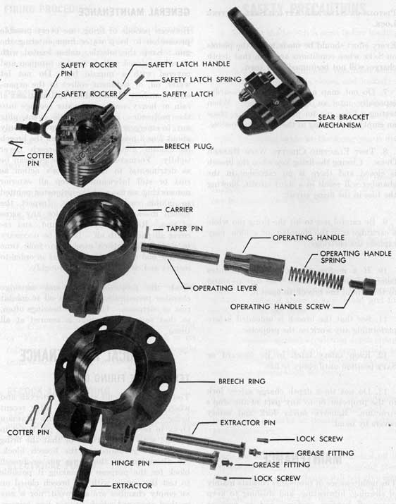
Figure 8.-Exploded View of Breech Mechanism.
|
17
|
|
THE ONLY WAY TO ELIMINATE ACCIDENTS ON CLOSED BREECH TESTS IS TO MAKE ALL ELECTRICAL TESTS WITH THE BREECH OPEN.
The approved method of testing follows:
1. OPEN THE BREECH, making sure the firing pin has been retracted.
2. Close the master switch and the contact maker (on the bridge) to the projector being tested.
3. Using a lamp of proper voltage that draws at least one ampere, place one lead from the lamp on the rear (exposed) end of the firing pin and the other lead to ground (preferably on the breech plug).
4. Normal illumination of the lamp indicates a satisfactory circuit, whereas failure to light indicates a short circuit, an open circuit, or a blown fuse. Although a dimly glowing light does not necessarily mean that the projector will fail to fire electrically, the reason for it should be determined and corrected. A voltmeter may be used in conjunction with the lamp if desired. However, voltmeter readings alone do not give a proper indication of the condition of the circuit, since partially open circuits or loose connections cannot be detected by the voltmeter.
DISASSEMBLY OF THE BREECH MECHANISM
To repair, inspect, or thoroughly clean this mechanism, it is recommended that the entire unit, or the carrier alone, be removed from the projector and worked upon where there is no chance of losing any parts overboard. The unit or the carrier should be placed in a container of kerosene or naphtha and allowed to soak for 15 to 20 minutes. If the carrier only is to be removed, follow first steps 9 and 10, as listed below; then follow the remaining steps in order to disassemble the parts.
1. With the breech block locked in its closed position, remove the safety rocker by
|
|
pulling the cotter pin and removing the rocker pin.
2. Lift the firing lever into its fired position.
3. Remove the firing pin assembly by turning to the left with the special pin wrench provided.
4. Rotate the operating handle to the left so that it is in the opening position, and remove the operating handle screw, spring, and handle.
5. Remove the operating lever by driving its taper pin out (use 7/64-inch punch) from the sear bracket side.
6. Unscrew the safety latch handle to remove the safety latch and safety latch spring.
7. Unscrew the breech plug from the carrier.
8. Remove the sear bracket assembly.
9. Remove the carrier by removing the lock screw, cotter pin, and hinge pin.
10. Disconnect the extractor by removing the lock screw, cotter pin, and extractor pin. Before removal, note carefully which side is up, so that the extractor will be replaced correctly. The extractor can be removed and replaced without removing the breech ring from the projector.
After disassembling the breech mechanism, carefully clean and inspect all parts. Remove any rust, rough spots, or nicks on the breech threads, using a file if necessary.
Reassemble the breech mechanism in the reverse order of removal, oiling or greasing all bearing parts as they are assembled. All taper pins are to be tapped in lightly so that they can be removed if necessary. Do NOT DRIVE. Use new taper pins if the old ones are deformed.
|
18
|
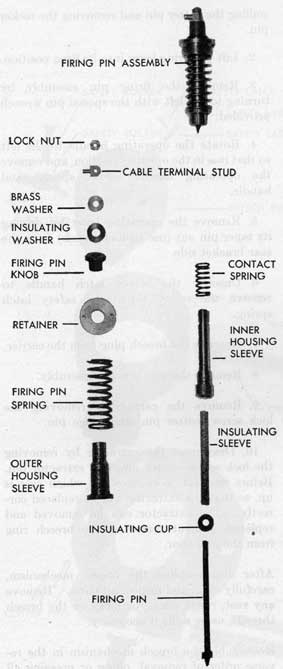
Figure 9.-Exploded View of Firing Pin
Mechanism.
|
|
After cleaning and reassembling, work the operating handle and breech plug several times to be sure that the unit works smoothly and does not bind or catch.
The entire breech assembly is interchangeable for the projectors Mk 6 Mod 1 and Mk 6 Mod 2, but some of the parts of the assemblies are not interchangeable.
DISASSEMBLY OF FIRING PIN MECHANISM
Remove the firing pin assembly from the breech block and disassemble its parts in the following order:
1. Remove the cable terminal stud and lock nut with a pair of small pliers or open-end wrench. Since the firing pin is loose at this stage of the disassembly operation, care must be exercised to prevent its falling out.
2. Remove the firing pin. Keep the retainer pressed down on the firing pin spring during this operation.
3. Remove the firing pin spring.
4. Remove the outer housing sleeve.
5. Remove the inner housing sleeve and contact spring.
6. Remove the firing pin insulation cap and sleeve.
To reassemble after cleaning and inspecting, replace the parts in reverse order of removal, oiling them as they are put together.
The firing pin assemblies in Projector Mk 6 Mod 1 and Mod 2 differ slightly. The entire firing pin assembly of the two projectors is interchangeable, but some of the parts are not.
|
19
|
|
After reassembling in the breech block, operate the firing pin several times to be sure it is functioning properly.
DISASSEMBLY OF SEAR BRACKET MECHANISM
The sear bracket parts may be disassembled either without removing the sear bracket from the breech block or by removing it and working on it outside the breech block.
To remove the parts, proceed as follows:
1. Drive out the sear shaft taper pins, from the under side (with a 1/8-inch punch) and if necessary the firing lever taper pin to disconnect the firing lever from the sear shaft.
2. Extract the firing lever and sear shaft to release the sear from the sear bracket.
3. Remove the toggle cotter pins and the toggle shaft bushing.
4. Pull the toggle shaft out of the sear and the sear toggle, being careful to hold the sear toggle and spring.
Clean and inspect the parts and then reassemble in the reverse order of removal. In reassembling, be careful to place the toggle spring over the sear toggle with the anchor ends on the top side, and be sure the cotter pin end of the shaft is toward the firing lever side. Tap taper pins snugly into place, but Do NOT DRIVE THEM. If it is necessary to ream these holes, use a No. 1 reamer for the sear and sear shaft hole and a No. 0000 taper reamer for the firing lever hole. (Ream from the top side.)
|
|
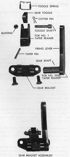
Figure 10.-Exploded View of Sear Bracket
Mechanism.
|
20
|
|
Note: On any repair job, always use new taper pins if the old ones are deformed.
SAFETY PRECAUTIONS
1. See that the breech is open before loading an arbor and depth charge.
2. See that the applicable condition below until the breech is closed and locked:
(a) The firing key or switch is open at the control station, or
(b) The firing cable at the firing pin is disconnected.
3. Do not keep a cartridge in the breech chamber except when in a danger zone. It can be loaded in ten seconds.
4. Keep the charge and arbor lashed to the sea lashing hooks unless immediate firing is contemplated.
5. Do not fire a projector if water or oil has collected in the expansion chamber. Remove the drain plug if there is any doubt, and fire with the vent left open.
6. To guard against accidental depth charge explosions, keep the depth charge pistols set on SAFE until the depth setting has been ordered in preparation for firing.
Undamaged Depth Charges Mk 6 and Mk 7 may be prevented from detonating, as a general rule, only by leaving safety forks in position or by setting pistols on SAFE.
Since the safety forks may be knocked off by explosions and flying material, keeping them in place on the depth charge will not give complete assurance that depth charges will not explode if accidentally dropped overboard.
The most positive way to guard against accidental depth charge explosion is to SET THE PISTOLS ON SAFE.
|
|
Every effort should be made to set the pistols on SAFE when conditions are such that depth charges will not be used immediately.
7. Do not snap a firing pin unnecessarily, especially into an empty chamber. When testing a firing pin for percussive firing, place an empty shell casing in the breech if possible.
8. TEST ELECTRIC CIRCUIT WITH BREECH OPEN. Closing the firing key when the breech is closed and there is no cartridge in the chamber will result in a short circuit, blowing the fuse in the firing circuit.
9. Be careful not to hit the firing pin while a cartridge is in the chamber, for a blow may explode the cartridge.
10. If a misfire occurs, wait 10 minutes before opening the breech. Be sure to stand to the side of the breech to open it.
11. See that the breech is unloaded before performing any work on the projector.
12. Keep safety latch in its forward or SAFE position until ready to fire.
13. Do not tie a depth charge safety fork to the projector or to any part of the ship's structure. Remove safety fork and safety covers by hand.
SUPPLY
The Bureau of Ordnance supplies and retains cognizance over the following items:
Depth Charge Projectors Mk 6 and Mods
Arbors
Depth charges and Impulse cartridges
Breech Covers Mk 2
|
The Bureau of Ships supplies and will retain cognizance over all electrical wiring including cable and fittings from the projector mount to the first junction box.
|
21
|
|
DISTRIBUTION
Requests for additional copies of OP 831, Revision 1, should be directed to the nearest BuOrd Publications Distribution Center: Navy Yard, Washington, D. C.; Mare Island, California; Adak, Alaska; Pearl Harbor, Hawaii; Espiritu Santo, New Hebrides; Exeter, England. Distribution Center mailing addresses should be obtained from list 10 nn on the Standard Navy Distribution List.
DISTRIBUTION:
Standard Navy Distribution List No. 25.
2 copies each unless otherwise noted.
1. a, d, h, i, k, 1; 2. (10 copies) c, h, j, k, n, v; 3.*, b, c, e, e-1, f, j, k, 1, o-r, y, y-1, aa, dd, ee, hh, jj, kk, 11, nn., uu, vv-1, vv-2, vv-3, vv-4, ww, xx, yy, bbb; 4. *, b, c, e, f, j, k, 1, p, q, r, y, aa, dd, ee, hh, jj, kk, 11, nn, uu, ww, xx, yy, bbb ; 5. b; 6. (10 copies) a; 7. f, h; 7. (5 copies) a-c, p*; 7. (10 copies), a, u*; 8. b*, j, n (SPECIAL LIST G, K, R, W, Y, GG), hh*; 10. qq, ss; 10. (25 copies), nn; 11. a (BuShips); 12. a, b (Revision 1); 14. (50 copies), a, k, m, s.
*Applicable addressees.
|
|
|