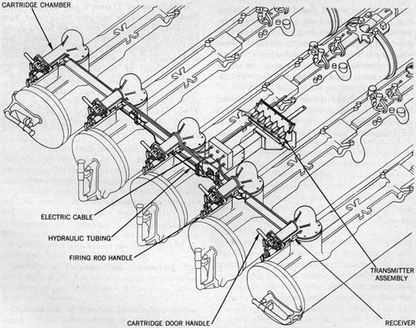
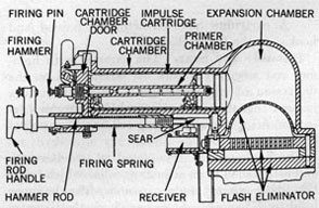
Firing Mechanism Mk 4 Mod 0, figure 60, consists of five cartridge chamber assemblies, one fastened to the top of each barrel near the breech end, with manual or hydraulic percussion and electrical firing controls.
Design Features
Two types of firing mechanisms are available. Both are designated Firing Mechanism Mk 4 Mod 0. The original design provided manual percussion
control; however, some torpedo tubes have hydraulic percussion control (NAVORD ORDALT 2905). When using the manual type, the gyro setter pulls the control cable handle, which trips the sear and causes the firing rod hammer to strike the firing pin. The hydraulic type functions in a similar manner but the sear is operated hydraulically.
The impulse power charge can be ignited electrically (as an alternate to either the manual or the hydraulic type) to fire the torpedoes.
Figure 60-Firing Mechanism.
47
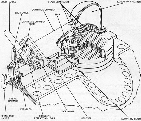
Figure 61-Firing Mechanism Components.
The firing mechanism houses the impulse powder charge, ignites it either electrically or by percussion, and provides an expansion chamber for the gases which eject the torpedo. The torpedo is given a minimum speed of 50 feet per second as it leaves the barrel.
The cartridge chamber is capable of withstanding a hydrostatic pressure of 900 pounds per square-inch for a period of at least 5 minutes without leakage or permanent deformation.
Components
The firing mechanism consists of the following principal components, figure 61.
Cartridge chamber
Flash eliminator
Door
Operating (firing rod) handle and firing pin
Hammer and sear
Manual or hydraulic percussion controls
Electrical firing assembly
Impulse cartridge.
Component Arrangement
A cartridge chamber assembly and flash eliminator are bolted to the T-guide on each of the five barrels, with the cartridge chamber door facing the breech end. A firing control cable or a
48
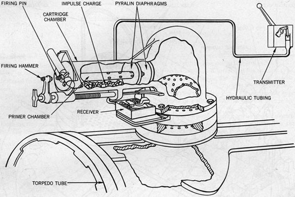
Figure 62-Firing Mechanism, Functional Arrangement Before Firing.
hydraulic receiver, which actuates the sear for percussion firing, is attached to each assembly.
The percussion firing handles in a selector housing or the hydraulic transmitter assembly, behind the gyro setter's seat, control the order of fire by percussion for all five barrels. Electrical firing is controlled from either the torpedo firing panel in front of the trainer's seat, or the bridge. A tube can be fired electrically, whether or not the firing handle is cocked, as long as the cartridge chamber door is closed to complete the circuit. Functional arrangement of the hydraulic firing mechanism is illustrated in figures 62 and 63.
Component Description
Cartridge Chamber. A cylindrically shaped cartridge chamber, figure 64, projects horizontally from the dome-shaped expansion chamber.
The cartridge and expansion chambers are castings of manganese bronze. Each casting is seated on its flash eliminator and is bolted to a machined pad on top of the T-guide.
An end flange, figure 61, for the cartridge chamber door is formed on the cylindrical cartridge chamber. A latch hood, or guard bracket, is mounted at the side of this end flange, away from the door hinge pin, and covers the latch hook, figure 65, on the door handle to prevent it from being struck accidentally by hand or by a canvas cover under the impact of a wave.
The flash eliminator is made up of a hemispherical, perforated steel screen and two perforated steel plates separated by a spacing ring. A locating pin, through the plates and spacer, prevents alignment of the holes, so that they will remain staggered. Staggering the holes sufficiently retards the passage of flaming powder gases so that they will burn out before they reach the open muzzle. The holes through the lower plate are inclined a slight angle to direct the gases away from the T-guide, for its protection.
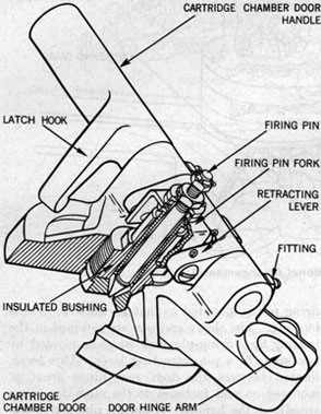
Door. The cartridge chamber door, figure 65, is a steel, disk-shaped casting with three integrally cast hinge arms projecting from its rear face.
49
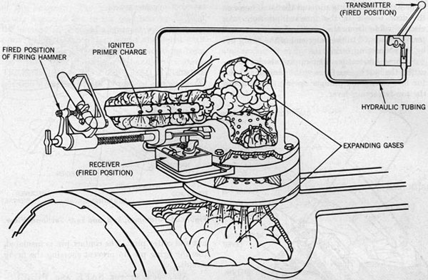
Figure 63-Firing Mechanism, Functional Arrangement After Firing.
Two of these three arms project to the rear for hinging the handle and one projects to the side for hinging the door itself.
The door is hinged through its side arm on the end flange of the cartridge chamber with a hinge bolt secured by a castellated nut and cotter pin. When the door is closed, it is reinforced by the flange socket to prevent a fired cartridge being blown back by impulse pressure.
HANDLE. The cartridge chamber door handle and latch hook is bored for part of its length to receive an operating spindle. The handle is riveted to this operating spindle which, in turn, pivots in the two rear hinge arms of the door. When the door is closed, the latch hook on the handle engages a lip on the flange to latch the door. When the handle is turned to release the latch hook, a retracting lever withdraws the head of the firing pin into the door, which then can be opened.
FIRING PIN. A firing-pin bearing, threaded to the center of the door, retains an insulated bushing. The firing-pin sleeve with the insulated
firing pin is mounted so that it can slide in this bushing. The sleeve and pin are retained in the bearing by a firing-pin fork which is pivoted by two studs to a pin-retracting lever. This lever, located between the door rear hinge arms, is mounted on and fastened to the same operating spindle as the handle. A spring plunger in the door presses against the top of the pin-retracting
Figure 64-Cartridge Chamber.
50
lever to hold the firing pin and the latch hook on the door handle in the forward position. An electric cable from the electrical firing control panel is fastened to the outer end of the firing pin by its connecting terminal.
Three lubrication fittings provide for lubricating the bearing surfaces of the hinges, and one for lubricating the plunger spring that actuates the pin-retracting lever.
Figure 65-Cartridge Chamber Door and
Operating Mechanism.
A cartridge case extractor is chained and hooked to the firing chamber.
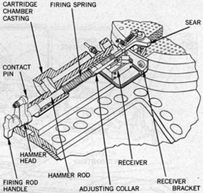
Hammer and Sear. The hammer with hammer rod assembly, figure 66, is mounted on the underside of the cartridge chamber in such a manner that the hammer is cocked ready for percussion firing when the firing rod handle is pulled back.
The hammer rod is mounted in two bearings and is threaded to an adjusting collar which holds the firing spring under tension. The hammer head, just forward of the handle on the hammer rod, contains a contact pin which is secured by a
Figure 66-Hammer, Rod, and Sear, Sectional View.
nut and cotter pin. The contact pin is insulated, like the firing pin, to prevent shorting the firing circuit.
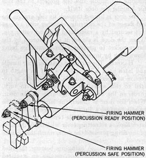
ARRANGEMENT FOR SAFE AND PERCUSSION POSITIONS. A keyway and a key notch, 90 degrees apart, are cut in the hammer rod forward
Figure 67-PERCUSSION SAFE and READY Positions.
51
of the hammer. The keyway and notch alternately engage a key in the rear bearing to keep the hammer in or out of alignment with the firing pin. The SAFE position, out of alignment with the firing pin, is 90 degrees counterclockwise from the breech, with the firing rod handle horizontal. The hammer is in the PERCUSSION READY position when the handle is vertical and the hammer is in line with the firing pin. These positions are shown in figure 67.
The sear is held in its bearing by a pivot pin, and acts as a rest or stop for the end of the hammer rod when ready to fire by percussion. The contacting surfaces of the hammer rod and sear are sloped so that the firing spring in forcing the hammer rod against the sear tends to push the
sear in the direction opposite to that in which it must move to fire the tube. A plunger spring in the sear serves to align the sear with the hammer rod when the hammer is cocked. The sear is operated manually or by the hydraulic receiver.
A lubrication fitting on the sear provides for lubricating the plunger spring and the bearing on which the sear pivots.
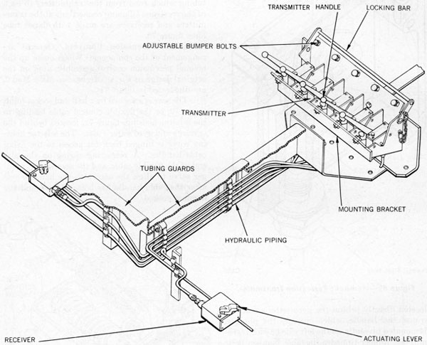
Hydraulic Percussion Controls. General arrangement of the components which comprise the hydraulic percussion control assembly are illustrated in figure 68, and are described in the following paragraphs.
TRANSMITTER ASSEMBLY. The five hydraulic transmitter assemblies, one of which is illustrated in figure 69, are mounted side by side on a bracket
Figure 68-Hydraulic Percussion Controls.
52
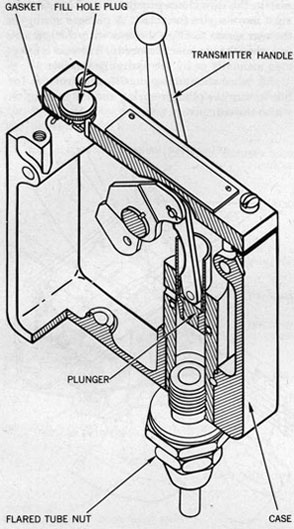
Figure 69-Hydraulic Percussion Transmitter.
located directly behind the gyro setter's seat. A transmitter handle, which operates the plunger, is mounted pivotally on the left side of each transmitter. Rubber-tipped adjustable bumper bolts are provided at the synchronized and full-stroke positions to relieve the shock that results from hard stroking of the transmitter handle. A locking bar and pin assembly is attached to the mounting bracket to lock the percussion firing control mechanism until ready for use. Removal of the locking pins permits the bar to swing clear of the stroking range.
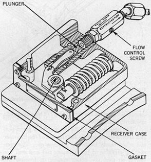
RECEIVER ASSEMBLY. A mounting bracket, bolted to the top plate of the flash eliminator,
provides a support for bolting a receiver assembly, figure 70, beneath each of the five cartridge chambers. A receiver lever is keyed to the receiver shaft and is secured by a nut and bolt through the split end. This lever moves through 60 degrees rotation to trip the sear.
Tubing guards and brackets between firing chambers and attached to the transmitter assembly bracket support the clamps for the 1/4-inch copper tubing which runs from the transmitters to each of the receivers. Tubing connections at the transmitters and receivers are made with flared tube nuts, figure 70.
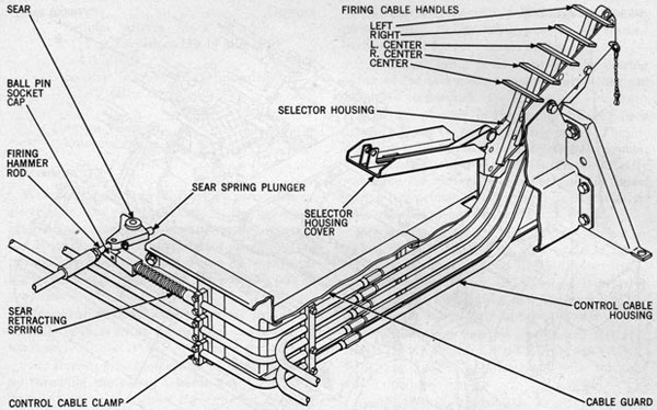
Manual Percussion Controls. General arrangement of the components which make up the manual percussion control assembly, used on the original design of Firing Mechanism Mk 4 Mod 0, are illustrated in figure 71.
The sear is attached by a ball and socket joint, figure 72, to the flexible control cable leading to the selector housing, figure 71, located behind the trainer's and gyro setter's seat. The selector housing cover is hinged back for access to the firing cable handles. A retracting spring on the sear end of the flexible cable, and the sear spring plunger serve to align the sear with the hammer rod after the cable handle has been released and the hammer cocked.
Figure 70-Hydraulic Receiver Assembly.
53
Figure 71-Manual Percussion Control System.
Figure 72-Manual Percussion Firing Assembly.
54
Figure 73-Firing Cable and Connections.
Electrical Firing Assembly. Cables from each of the firing chambers are connected in the quintuple receptacle located between the center and right-center barrels, figure 73. Cables lead from this receptacle to the torpedo firing panel in front of the trainer's seat and through the central pivot assembly to the torpedo firing system on the bridge.
A cable is connected to each firing pin by a terminal which is secured by a nut on the end of the firing pin.
The electrical firing circuit is grounded in the firing chamber through the firing pin and primer. For further details of this circuit, refer to chapter 11.
Impulse Cartridge. Impulse Cartridge Case Mk 2 Mod 0 is a brass cylinder with a flat head. The primer chamber is threaded to the center of
this head. The powder charge, surrounding the primer and filling case, is retained by pyralin diaphragms, figure 62.
The primer chamber is a tube of rolled naval brass containing a primer seat in the breech and a plug in the other end. Between the ends is a series of radial exit holes. Percussion-Electric Primer Mk 20 is screwed permanently into the primer seat.
CARTRIDGE DATA
DIMENSIONS
INCHES
Case:
Outside diameter
3.24
Inside diameter
3.03
Overall length
12.70
Primer:
Outside diameter
0.875
Overall length
11.20
55
WEIGHTS
OUNCES
Sodium nitrate black powder (For Torpedoes Mk 14 and 15, All Mods)
38.0
Sodium nitrate black powder (All other torpedoes)
35.0
TORPEDO VELOCITY
FEET-PER-SECOND
Potential minimum
50.0
Operation
When a torpedo is fired either by percussion or electrically, the powder charge in the primer is ignited and flame passes from the primer through the holes in the primer chamber to ignite the powder charge in the impulse case. The expanding gases which result force the torpedo out of the tube.
Electrical Firing. The electrical firing circuit, figure 74, is set up for firing in the following manner:
1. Barrels to be fired are set up at the director by throwing the barrel selector key. The 6PA circuit thus is energized through the transfer switch to the firing panel on the tube mount.
2. After the barrels have been readied, the READY switch on the tube mount is closed.
3. The 6PA circuit now is complete from the power supply to the firing pins in the readied barrels except for the contact maker.
4. Actual firing is accomplished by closing either of the two contact makers, since they are connected in parallel.
A spring plunger in the firing chamber door presses against the pin-retracting lever. The firing pin is held in electrical contact with the primer. The mechanism now is ready to fire electrically whenever the cartridge chamber door is closed upon a live primer. The tube can be fired electrically whether or not the hammer is cocked.
Percussion Firing. The firing hammer is cocked, PERCUSSION READY position, figure 75, by pulling the firing rod handle (in its vertical position) straight back and allowing it to move forward, with the keyway and key engaged, until the hammer rod rests against the sear.
The transmitter handles are marked RIGHT, RIGHT-CENTER, CENTER, LEFT-CENTER, and LEFT to correspond with the tube which operates.
Each hydraulic transmitter handle operates a plunger in the transmitter assembly to force hydraulic fluid through a tube to the receiver assembly where it acts upon a piston that actuates the
pivotally mounted lever. This lever pushes the sear out of the way to allow the firing spring to push the hammer rod forward. A flow control valve, installed between the receiver and its hydraulic fluid line, permits the slow return of the transmitter handle to its normal position.
In manual percussion, pulling the firing cable handles, figure 71, causes the flexible cable to trip the sear, releasing the firing hammer rod to fire the torpedo.
The primer is fired by percussion when the hammer strikes the firing pin after the spring-loaded hammer rod has been released by the sear.
Maintenance
Inspection. Make the following WEEKLY inspections:
1. Inspect all moving parts of the firing mechanism to see that they are in good operating condition. See that the cartridge chamber is clean.
2. See that the contacting surfaces of the hammer rod and sear engage properly and that they are bright, unburred, and sloped so that if they come in contact violently (as under the impulse of the firing spring) the sear will be driven towards its stop rather than away from it. Worn sears and hammer rods should have their contacting surfaces restored to the proper angle (SA dwgs 80994 and 88384), using the profile gage authorized for that purpose.
3. Check the electric firing cables for cracked or worn coverings and make sure that all connections are secure. Determine and record
57
insulation value. Replace all cables that appear to be defective.
4. Check the hydraulic percussion system for dented or flattened tubing and make sure that all connections are tight.
5. Check the manual firing control cables for rusting, and lubricate with bearing grease MIL-G-16908 (BuOrd). It may be necessary to withdraw the cable from its assembly for lubrication. Refer to Disassembly, page 59 for instructions.
6. Inspect batteries. Test for voltage and specific gravity, adding distilled water as required. These batteries are under the cognizance of the Bureau of Ships and are located as convenient, below decks.
7. Examine the point of the firing pin and the face of the cartridge chamber door around it. Make certain that the point of the firing pin is rounded to a radius of about 0.05 inch and that it is smooth and unmarred.
8. Inspect each impulse cartridge to make sure it has not been damaged by moisture. If the pyralin diaphragms are cracked or loose or the exposed areas of the diaphragms are not covered entirely with lacquer, or the primer is not tight, the cartridge cases must be reloaded.
Lubrication. Exposed areas, particularly near the bearings of the firing hammer rod, must be oiled DAILY or after 4 hours of operation. WEEKLY, or after 30 hours of operation, lubricate the hinges of the firing chamber door and handle by applying the authorized grease through the lubrication fittings. The springs and plungers for the pin-retracting lever and sear (and its bearing) also are provided with fittings through which they must be lubricated WEEKLY. Every WEEK coat the spring on the firing hammer rod with grease. Lubricate all of these parts as soon as practicable after firing torpedoes. Refer to chapter 12 for authorized lubricant and frequency of application. Be sure all moving parts are exercised thoroughly after lubrication.
Exercise. The following exercise routines should be accomplished WEEKLY.
1. Cock and trip the hammer. Make certain that the sear is rotated properly against its stop to engage the front end of the firing rod when the hammer is cocked.
2. Pull the handle on the hydraulic transmitter (firing cable handles on manual system);
370563 0-56-5
make sure that the sear is moved properly to trip the hammer, by the lever on the receiver in the hydraulic system and by the flexible control cable with its retracting spring and spring plunger in manual control system.
3. Try the action of the firing pin in response to rotation of the firing chamber door handle, making sure that the firing pin moves freely without sticking. If it does stick, disassemble the firing pin from the door, clean and lubricate as required.
QUARTERLY, test the mechanism electrically by firing a primer in each barrel from the bridge. Be sure the breech door of the barrel is open.
Preservation. Make certain that there is no corrosion on the firing pin or on the adjacent area of the face of the firing chamber door. Be most particular to see that no corrosion or salt bridges the air space between the firing-pin point and the metal bushing in the door or over the top of the insulation which separates that bushing from the body of the door. The edge of this insulation appears as a narrow ring surrounding the firing-pin bushing. Cover the point of the firing pin, the air space between the pin and the bushing, the face of the bushing itself, the insulation, and an area of about two inches in diameter on the face of the cartridge chamber door with Gun Slushing Compound MIL-C-18487 (NOrd) Grade A, applied cold.
Due to the character of the residue of the powder used in these tubes, all parts fouled by the powder must be cleaned as soon as practicable after firing. First, remove the cartridge chamber and flash eliminator from the barrel. Scrape out any caked powder residue. Wash with kerosene or hot, fresh water and soap or washing soda. When thoroughly dry, coat all surfaces of the flash eliminator and the machined cartridge-case bore in the chamber with Bearing Grease, MIL-G-16908 (BuOrd), and reassemble. Replace any plate or dome of the flash eliminator when any spot is reduced to one-half its original thickness or when any two holes have spread into one.
Operating Instructions
To operate the firing mechanism:
1. Pull each firing hammer handle straight back and rotate 90 degrees to the left (counterclockwise viewed from the rear of the barrel) to horizontal position; allow the hammer rod to
58
engage in its PERCUSSION SAFE position. (Refer to insert, figure 75.)
2. Grasp the handle of the cartridge chamber door, unlatch it by turning it away from the operator and swing the door up and over to the right until the door is fully open. Load the impulse case into the chamber.
3. Dab Gun Slushing Compound MIL-C18487 (NOrd) Grade A, applied cold, over the point of the firing pin and entirely cover the insulation which is visible around it.
4. Close the cartridge chamber door. Since the impulse case contains a live primer, the mechanism now will fire electrically when the firing circuit is closed, regardless of the position of the firing hammer. Now grasp the firing hammer handle, pull it back slightly to release the detent which holds it in the PERCUSSION SAFE position, and rotate the handle 90 degrees to the right (clockwise) to the vertical position; allow the hammer to go forward until the front end of the hammer rod contacts the sear. The firing hammer is now in the PERCUSSION READY position. (Refer to insert, figure 75.) For greater safety, the firing chamber door may be left open until after the firing hammer has been placed in PERCUSSION READY position.
Operating Precautions. Firing circuits should be tested before the "ready" period. Use test lamps or voltmeters across the firing pins and tube. It is just as important to make sure that the circuit is open when the firing switch is open as it is to make sure that the current flows when the firing switch is closed. The firing circuit also may be tested by firing a primer in an empty cartridge case with the breech door of the torpedo tube open.
Impulse cases should not be loaded into firing chambers except when the need for being ready to fire is considered imminent, and then only when it is the immediate intention to train the tube to a bearing at which it is safe to fire. In order to overcome some of the objections to such delay in loading, ready service containers for the impulse cases have been installed near the tubes. The use of firing mechanism plugs has been authorized to prevent the entry of water into the firing chamber when no impulse case is loaded.
Except under actual battle conditions, when training from one beam to the other, open the firing chamber doors while training through sectors
in which a torpedo, if fired, would land on the ship. When the cartridge chamber door is open, neither the electrical nor the percussion systems can fire the tube.
WARNING
DO NOT LET THE IMPULSE CASE SLIDE OUT WHILE THE CARTRIDGE CHAMBER DOOR IS OPEN.
The practice of installing canvas covers on loaded cartridge chambers is hazardous. Accidental firing of torpedoes has been reported under circumstances which indicated that the tubes may have been fired by percussion resulting from the impact of green water upon the relatively large areas presented by such canvas covers, even though hammers were set so as not to fire by percussion.
To avoid carrying a heavy load on the firing spring for extended periods the firing hammer must not be let down on a primer. Not only is there danger of the tube being fired by a nearby concussion, but the firing hammer handle may slip from the operator's hand while he is attempting to pull it back, or the sear may be held away from its engaging position by ice or rust. In either case, the tube probably will be fired.
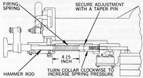
Adjustment
Hammer Rod. The position of the collar on the hammer rod governs the pressure of the firing spring. This pressure can be adjusted when installing a new hammer rod or spring by shifting the collar on the rod to which it is threaded. When the desired load of 62.5 pounds to compress the spring 4.15 inches has been reached the collar's position should be secured with a pin as illustrated in figure 76.
Figure 76-Hammer Rod Adjustment.
59
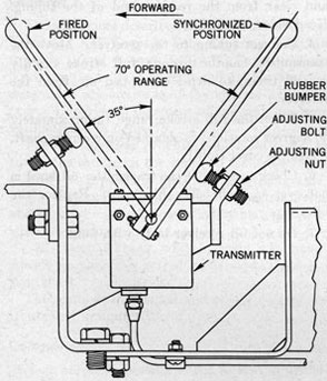
Transmitter Handle (Hydraulic Control). Rubber bumpers on the adjusting bolts at each end of the handle stroke \relieve the shock of a hard stroke. Bolts should be adjusted so that the handle strikes the rubber bumper just before reaching the synchronized And full-stroke positions. Adjustment details are illustrated in figure 77.
Figure 77-Transmitter Handle Adjustment.
Flow Control (Hydraulic System). Adjust flow control screw, figure 70, to slow the return of transmitter handle so it will not be thrown hard against the bumper.
Disassembly and Reassembly
Disassembly of Manual Firing Mechanisms. Refer to BuOrd dwgs 217770, 217771, and 217772.
1. Remove the ball cap from the ball socket, figure 72, which engages .the ball-tipped stud projecting downward from the sear at each firing chamber.
2. Unfasten and unscrew each ball socket from the firing cable. On early tubes the socket is secured against unscrewing by a 1/16-inch cotter pin. On later tubes it is secured by a setscrew with a soft copper plug beneath (to avoid marring the screw threads on the cable end). Do
NOT LOSE THIS SMALL COPPER PLUG. Ball sockets secured by cotter pins consistently have caused trouble. Before reusing one of this type, test by a pull of not less than 100 Pounds on the cable.
3. Pull cable up at the selector housing and unscrew the firing handle.
4. Unscrew the small, round locknut from the end of the cable and unscrew the sleeve from the cable so it can be pulled through its housing tube.
5. Pull the cable out of its housing tube from the rear.
6. Remove the cable guard of inverted U-section which joins the cable bracket (mounted on the firing chambers of the center and right-center barrels) to the cable housing and mounting bracket, upon which the firing selector is mounted.
7. Remove all cable clips and caps which secure the tubular cable housings to the cable brackets between firing chambers, and remove the cable clamp which joins the five housings just forward of their bends.
8. Uncouple and remove the after parts of all five tubular cable housings.
9. Remove the cable brackets between firing chambers.
10. Remove the firing-selector housing with the forward portions of the five cable-housing tubes attached.
11. Remove firing chambers and flash eliminators.
Removal of Hydraulic Transmitters and Receivers.
1. First drain the system of its hydraulic fluid by disconnecting the tubing at the receiver.
2. Disconnect all flared tube nuts at the receivers and transmitters.
3. Disconnect and remove all clamps and brackets holding the tubing.
4. Unbolt and remove each receiver from its bracket.
5. Unbolt and remove each transmitter from the bracket, which in turn can be unbolted and removed from its position behind the gyro setter's seat.
6. Drain oil remaining in the transmitter reservoir.
Removal and Disassembly of Cartridge Chamber. The cartridge chamber door assembly, firing pin, and firing hammer and rod assembly all can be removed from the cartridge chamber
60
before it is unbolted and removed with its flash eliminator from the top of the T-guide.
Reassembly and Installation of Cartridge Chamber. Reassembly and installation is performed in the reverse order of removal and disassembly; refer to BuOrd dwgs 516353 and 516354 for assembly details.
Installation of Hydraulic Transmitters and Receivers.
1. Install the five receiver brackets, referring to BuOrd dwg 516353, and the transmitter bracket assembly, referring to BuOrd dwg 516355 and 516356.
2. Install the receiver and transmitter assemblies. Install brackets, tubing and clamps; refer to BuOrd dwgs 516352, 516355, and 516357 for general arrangement.
Filling and Bleeding Hydraulic Percussion Controls
1. Loosen screws on receiver cover to allow cover to raise approximately I/8 inch and disconnect tubing at receiver.
2. Station an assistant at the receiver end of the tube, fill the transmitter reservoir with Power Transmission Fluid MIL-F-17111 (NOrd), and from the synchronized position, move transmitter handle slowly to full stroke position. Have assistant keep his thumb over the receiver end of the tubing during the return stroke.
3. Repeat this operation until oil flows freely and clear from the receiver end of the tubing. Keep the reservoir filled.
4. Connect tubing to the receiver. Move the transmitter handle through full stroke rapidly several times, to expel entrapped air from the receiver.
5. When the full stroke range (approximately 60 degrees rotation) is obtained on receiver shaft, fasten the cover tightly.
6. Check to see that the transmitter oil level is not over 1/2 inch below filler cap. Replace the filler cap.
7. Do not fill receiver body with fluid.
61
Chapter 6 TRAINING GEAR
General
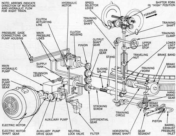
The equipment described in this chapter is designated 21" AW Torpedo Tube Training Gear Mk 6 Mods 0 and 1, and 21" AW Torpedo Tube Training Gear Mk 7 Mods 0 and 1. Each of the designated assemblies is of the electric hydraulic type. General arrangement of the training gear is illustrated in figure 78.
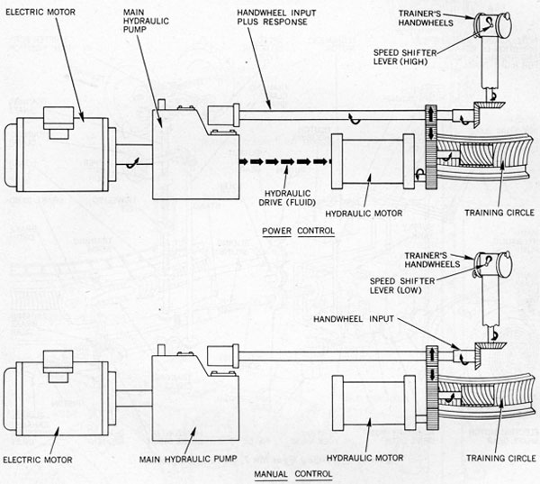
The training gear provides controlled power to
rotate the saddle on the stand to train the tubes.
Motivating power is dual and interchangeable:
1. POWER DRIVE, by means of an electric motor and hydraulic system, controlled by manual hand-wheel operation.
2. MANUAL DRIVE, whereby train is by hand-wheels mechanically geared indirectly to the worm gear shaft.
The methods of manual and power control are illustrated in figure 79.
Components
Each assembly consists of the following principal units and assemblies, figure 80.
Electric motor
Electric motor controller
Main hydraulic pump and valves
Auxiliary pump and valves
Hydraulic motor and clutch
Automatic brake.
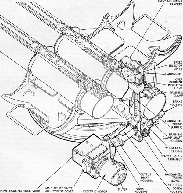
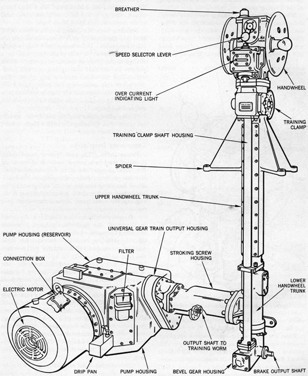
Component Arrangement
The handwheel mounting bracket and gearing form the top portion of a trunk which extends vertically above the left side of the center barrel. Mounted on this bracket are the training hand-wheels, the sight mounting bracket, a high- and low-speed selector lever, and the overcurrent indicator light, figure 78. Located inside are the
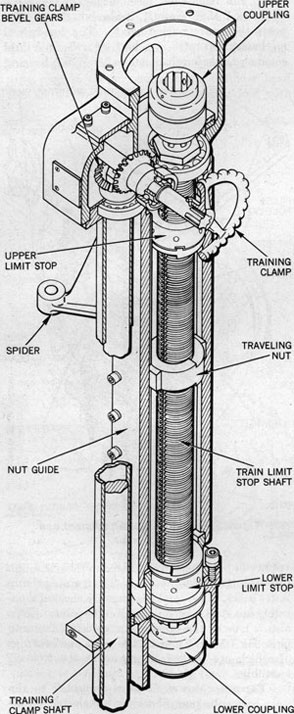
shifter fork, the selector and bevel gears, and the necessary shafts and bearings to transmit hand-wheel movement to the hydraulic control mechanism or to the output shaft. The trunk acts as an extension of the pump housing (reservoir) and augments the reservoir (capacity). Hydraulic fluid for the entire system is poured through a filler hole in the top of the handwheel mounting bracket, where there also is a breather cap for venting air from the hydraulic system. The upper handwheel trunk is under the mounting bracket. It contains the hand control training shaft and couplings, traveling nut with guides, the training limit stops, the training clamp shaft, bevel gears, and bearings. The training clamp is used to lock the tubes at any desired angle of train. The traveling nut and adjustable limit stops provide positive stops for maximum limit left and right.
The handwheel trunk lower end extends below the barrels, figure 81. It consists of two housings which contain bevel gears and bearings for both the training clamp shaft and the handwheel control mechanisms. The stroking screw housing is attached at one end to the handwheel trunk lower end and at the other end to the pump housing (reservoir). Training Gear Mk 7 and Mods has a third housing for a brake output shaft.
The pump housing (reservoir), which contains the major lower hydraulic components, is supported by a flange connection to the worm housing, a roller bracket, and a bracket on the underside of the left wing barrel. Inside this pump housing (reservoir) are mounted the hydraulic pump, hydraulic motor, neutral lock, friction clutch, and all transmission piping. Subassemblies within the housing include the stroking screw, differential drive gears, and (in Training Gear Mk 6 Mods 0 and 1) the brake assembly.
Design Features
Major Difference. Training Gear Mk 7 Mods 0 and 1 differ chiefly from Training Gear Mk 6 Mods 0 and 1 in that the automatic brake mechanism is not positioned with components of the
62
Figure 78-Training Gear Mk 7.
63
Figure 79-Manual and Power Control, Functional Diagram.
64
Figure 80-Training Gear Mk 7, Gearing Diagram.
65
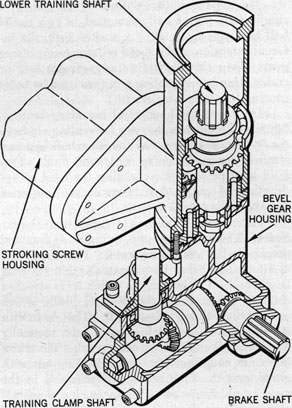
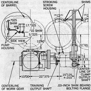
Figure 81-Power Drive Mk 7, Housing and Gearing.
66
hydraulic unit, but is located on the worm housing of the training gear.
Minor Differences. Among the minor design differences, most of which result from the different braking arrangements, are the following: Training Gear Mk 6 Mods 0 and 1 have a shipping plug in the automatic brake cylinder head and an externally mounted brake manifold with
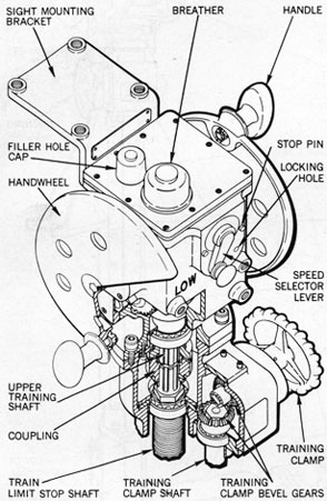
Figure 82-Handwheel Mounting Bracket.
check valves; the lower trunk gear housing does not include a brake output shaft.
There are slight differences in sleeve couplings and drive gear training shafts. A sludge pot with petcock is a feature of Training Gear Mk 6 Mods 0 and 1 only. Filters, while essentially the same in structure and function, differ in location. Ball bearings in the auxiliary pump differ slightly, as do hydraulic motor angle boxes, worm housings, cover plates, gear covers, and brake housings.
The only difference between hydraulic motors in Training Gear Mk 6 Mod 0 and Mk 6 Mod 1 is a slight redesign in the latter to make it identical to the motor used in Mk 7 Mods 0 and 1.
Training Gear Mk 7 Mod 1 differs from Mk 7 Mod 0 in the training gear drive, but models are interchangeable. Differences consist only in parts changes intended to aid production and in a change to the pitch of the stroking screw which reduces by one-half the lag between the hand-wheels and the output shaft at any speed. The new pitch also reduces by the same amount the overrun of the output shaft that is noticeable in all electric hydraulic drives when handwheels are stopped suddenly.
Wiring plans differ slightly but electric motors are identical in Training Gear Mk 6 Mods 0 and 1 and Mk 7 Mods 0 and 1.
Component Description
Power Drive. The term "power drive" refers to one of the two principal methods of operating the training gear, the other is "manual drive". Common to both systems are gears in the hand-wheel mounting bracket, shafts and gears in the handwheel trunk and the lower trunk gear housing, and the lower gears in the output shaft gear train.
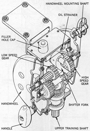
HANDWHEEL MOUNTING BRACKET. As shown in figure 82, the handwheel mounting bracket is flanked by two handwheels which are turned by their handles (upward and forward for right train, downward and backward for left) to train the tube either manually or hydraulically. Lubrication fittings are recessed in the handle ends. A sight platform is attached to the top (muzzle end) of the bracket. A speed selector lever faces the operator on the opposite side (breech end). This lever is used for shifting gears into either HIGH or LOW speed. Rotation of the hand-wheels turns the output shaft through the worm shaft to which it is coupled directly. In high gear, one turn of the handwheels will turn the worm shaft approximately three-fourths of a turn; in low gear, the handwheels must make approximately 2 1/4 turns to turn the worm shafts once.
Beneath this speed selector lever is the over-current indicating light. Excessive torque speed combinations of the training gear drive immediately are indicated by the lighting of the lamp.
67
The handwheels are splined to the ends of a single shaft horizontally mounted in two radial ball bearings, figure 81. A shifter fork, the internal extension of the speed selector lever, moves gears along this shaft into engagement left or right. Handwheel motion is transmitted by bevel gearing to the training shaft.
On top of the handwheel mounting bracket, figure 83, are the breather cap for venting air from the hydraulic system, and the filler hole cap and strainer for replenishing hydraulic fluid. Two fluid level petcocks for checking the level of hydraulic fluid contained in the system are positioned one above the other.
HANDWHEEL TRUNK (UPPER) AND LIMIT STOPS. The training clamp, figure 82, is mounted outside on the handwheel trunk. This clamp is a smaller wheel below the operator's right training handwheel. The housing to which its is attached contains the training clamp bevel gears, which operate the training clamp shaft. This shaft with its bearings is housed in a steel tube vertically mounted at the side of the main trunk. The training shaft, couplings, bearings, traveling nut with guide, and the limit stops are contained in the main trunk, figure 84. The upper stop is adjustable to permit from 0 degree to 330 degrees of train. The limit stop assembly makes unnecessary the bolting of external train limit stops to the stand as described in chapter 3, because these handwheel trunk limit stops are equally positive. Two cover plates located on either side of the housing may be removed for inspection or adjustment.
The assembly operates as follows: the traveling nut on the threaded shaft, figures 84 and 99, is prevented from turning by nut guides that parallel the shaft. When the shaft is turned by the handwheels, the nut, since it cannot turn with it, moves up or down the shaft (depending on the way the handwheels are turned) until it comes against one of the limit stops. These stops, also screwed on the threaded shaft, rotate with the shaft without moving up or down. The upper stop limits right train and the lower limits left train. When the nut contacts either limit stop, further train in that direction is stopped positively. The stops can be set to permit as much as 330 degrees of train.
HANDWHEEL TRUNK (LOWER). The lower end of the handwheel trunk, figure 85, houses the
lower gears, shafts, and bearings of the training clamp and handwheel mechanisms; in Training Gear Mk 7 Mods 0 and 1, it also houses and supports the brake output shaft. The handwheel mechanism operates in a bath of hydraulic fluid common to the mechanisms in the pump housing
Figure 83-Handwheel Attachment and
Arrangement.
(reservoir) and here is connected to them through the lower trunk gear housing. The training clamp lower gears, shafts, and bearings are encased separately in a steel tube, oil-sealed at the joints. This also is true of the brake output shaft (Training Gear Mk 7 Mods 0 and 1), the gears and bearings of which are packed in grease at the time of assembly.
ELECTRIC MOTOR. Flange-connected to the main hydraulic pump housing, the electric motor drives the hydraulic pump and an auxiliary pump, figure 80, through reduction gears. The reduction gear case is provided with an overflow passage
68
Figure 84-Handwheel Trunk and Limit Stops.
Figure 85-Lower End of Handwheel Trunk Shafting, Gearing, and Related Parts.
to maintain the proper fluid level. There is an inspection cover high on the motor mounting flange and a plug at the bottom for draining the gear case.
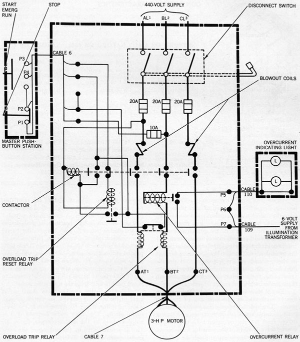
ELECTRIC CONTROLLER. An alternating current, nonreversing, magnetic controller encased in a watertight box is mounted on the bulkhead. It has a remote pushbutton and an indicator light located on the mount at the trainer's station. An overcurrent relay is incorporated to make contact
in a separate circuit to operate the overcurrent indicating light. The wiring diagram for the controller is given in figure 86.*
* This wiring diagram was derived from BuOrd dwg 231761. For other controller wiring diagrams, refer to BuOrd dwgs 268619, 427355, or 365843.
Figure 86-Controller, Schematic Wiring Diagram.
70
The controller is watertight, semiautomatic, and has an across-the-line starter controlled by a remote pushbutton. It has an ampere rating
(full load) of 4.91. As shown in table 1, the characteristics of controllers vary depending upon the specification to which they were manufactured.
Table 1 CONTROLLER CHARACTERISTICS
Characteristic
Manufacturing Specification
NAVORD OS 4144
NAVORD OS 4343
NAVORD OS 4533
Protection:
Overload
Thermal
Thermal
Thermal.
Adjustable range
5.1 to 6.1 amp
5.1 to 6.2 amp
5.1 to 6.2 amp.
Normal setting
5.9 amp
5.65 amp
5.65 amp.
Short circuit:
Line fuses
20 amp
20 amp
20 amp.
Pushbutton fuses
10 amp
10 amp
10 amp.
Undervoltage:
Drop-out voltage
44
44.
Sealing voltage
374
374.
Shockproof rating
Class 50
Class (150 min.) Class (2000 max.)
Class HI.
Weight, pounds
100
78.
Manufacturer
Cutler-Hammer, Inc
Cutler-Hammer, Inc
Cutler-Hammer, Inc.
BuOrd dwg
231761
268619 and 427355
365843.
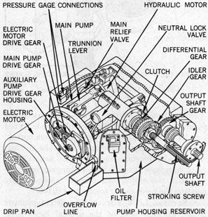
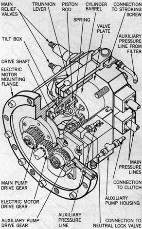
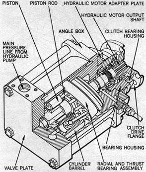
PUMP HOUSING (RESERVOIR). The pump housing, figure 87, fabricated of steel plate, contains the main hydraulic pump and the auxiliary pump. The housing forms a tank or reservoir of hydraulic fluid in which the principal components (hydraulic pumps, motor, and connections) function. It is supported by a flange connection to the worm housing, a roller bracket, and a bracket on the underside of the left barrel. Hydraulic fluid freely circulates through this pump housing (reservoir), the stroking screw housing, and up through the handwheel trunk.
Flange-mounted inside is the hydraulic pump, figure 88, flanked by the auxiliary or make-up pump. The hydraulic pump has parallel pistons, positive displacement, variable stroke, and is gear driven from the electric motor. In electric hydraulic drive, the end of the stroking screw moves a tilt box within the pump through an external
two-bar linkage. The amount of tilt regulates, proportionally, the rate at which fluid is pumped to the hydraulic motor. A drive shaft, mounted top and bottom in ball bearings, is gear driven by the electric motor to turn the cylinder barrel at a constant speed. Piston rods, ball-jointed at one end to pistons in the cylinder barrel, are ball-jointed at the other end to the tilt box, which also turns with the shaft. When the tilt box is tilted from its neutral position, the pistons move in and out of the cylinder barrel as the assembly turns, to pump fluid to and from the hydraulic motor.
STROKING SCREW AND LINKAGE. Axial movement of the stroking screw is permitted through a sliding spline, figure 80, connection to the horizontal shaft. The screw slides forward if it is not restrained by the detent plunger, figure 97. This is accomplished by the turning of the horizontal shaft and the differential gear through
71
which the screw is threaded. The screw directly engages a cross-head, the external regulator of the tilt box within the pump. These functions are discussed more fully under Operation, page 76.
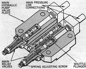
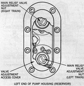
RELIEF AND MAKE-UP VALVES. The main relief valves and a shuttle type make-up valve, figure 89, replenish fluid for the main circuit from the auxiliary pump. They are incorporated in the valve plate with which the cylinder barrel makes contact by spring tension.
The main relief valves are two spring-loaded plunger type valves, one for each direction of tube train. The valves are held in position against low pressure by adjustable compression springs. These springs are set to yield under higher hydraulic pressure. Operation is as follows: as hydraulic fluid is vented from the pump, the pressurized fluid acts against the plunger valve, forcing it against the spring. The valve movement shifts its thicker part, unblocking a port connected to the low pressure side of the system, which permits the fluid to unload.
A make-up valve, next to the two relief valves, has a two-land shuttle plunger operating in a ported sleeve. The shuttle plunger contains differential areas located so as to cover input and output ports in accordance with the plunger's position as governed by varying pressure conditions
Figure 87-Pump Housing, Internal Arrangement.
Figure 88-Main Pump.
in the system. The function of the plunger is to permit entrance or obstruct exit of fluid for. the main circuit as required by operating demands of the pump.
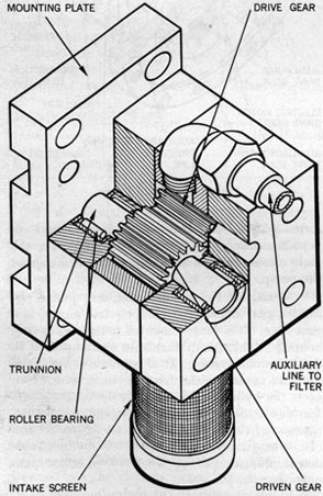
AUXILIARY PUMP. The auxiliary pump, figure 90, gear driven from the electric motor, is a gear type. It is flange-mounted to the main pump housing. This pump furnishes make-up fluid to the hydraulic system. It also provides hydraulic pressure to engage the friction clutch which connects the hydraulic motor with the output shaft for power drive, and to disengage the detent plunger of the neutral lock valve, figures 80 and 97. When the electric motor is not running, this detent plunger prevents the stroking screw from operating the tilt box.
Fluid intake from the hydraulic fluid reservoir (in which all hydraulic components are
72
Figure 89-Relief and Make-up Valves.
Figure 90-Auxiliary Pump.
immersed) passes through a screen attached to the underside of the auxiliary pump, figure 91. If the screen becomes clogged, a spring-loaded plunger opens to permit free flow of fluid to the pump.
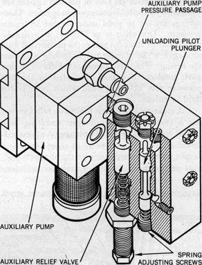
Mounted in the rear end plate, figure 91, is the auxiliary relief valve and an unloading pilot plunger. The plunger controls flow to the friction clutch and detent plunger. The auxiliary relief valve maintains pressure in the auxiliary pump discharge lines. This pressure is set by the
Figure 91-Auxiliary Relief Valve.
spring-adjusting screw. When the auxiliary pump stops, the unloading pilot plunger is forced into its unload position by its compression spring. This vents the hydraulic pressure to the friction clutch and the detent plunger of the neutral lock valve to release the clutch and plunger. Spring-operated, the clutch and plunger automatically position the mechanism for manual drive.
NEUTRAL LOCK VALVE. The detent plunger is the working part of the neutral lock valve. Underneath is a spring which pushes the plunger
73
up into the valve seat, locking the stroking screw. With the detent plunger engaged, the training gear can be operated in manual drive. Underneath the spring, at the bottom of the valve housing, is the cap or neutral lock plunger stop.
INTERCONNECTING PIPING (figures 88 and 89). The main hydraulic pump is connected to the hydraulic motor by the two pipes which join the ports of their respective valve plates. Piping from the auxiliary pump passes through the ports of the auxiliary relief valve and neutral pilot plunger to the neutral lock valve and to the clutch end of the hydraulic motor. Another line connects with the make-up valve in the main pump valve plate. A pipe from the auxiliary pump connects with the filter, figure 91, and a discharge pipe from the filter runs to the make-up valve in the main pump valve plate.
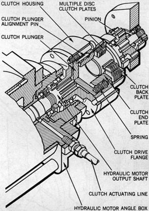
HYDRAULIC MOTOR AND CLUTCH. In power operation, the hydraulic motor, figure 92, drives the worm gear to train the tube. It has parallel pistons, positive displacement, and fixed stroke. This unit is connected hydraulically to the main pump by two pipes. The motor output shaft is splined to a multiple disk friction clutch. In
Figure 92-Hydraulic Motor.
370562 0-56-6
Figure 93-Clutch Operating Parts and Connections
to Related Components.
power operation, the clutch engages by auxiliary hydraulic pressure, and couples the motor output shaft to the pinion, figure 80. The pinion drives the output shaft, which is splined directly to the worm gear shaft.
The output shaft, figures 92 and 93, set in two radial ball bearings, is splined to the hub of the output gear, which is driven by a pinion connected to the clutch.
The hydraulically operated clutch, figure 93, is of the multiple disk friction type. It engages the motor output shaft with the output shaft gearing, to turn the worm gear in power drive.
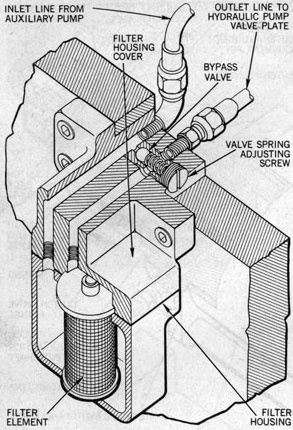
The oil filter, figure 94, consists of a metal filter element and a spring-operated bypass valve encased in a split bronze housing. The oil filter housing is bolted on the side of the pump housing above the drip pan, figure 87. The filter element is removed for cleaning by unbolting the filter housing cover. The inlet and outlet line tapped
74
Figure 94-Filter Components and Connections.
holes must be plugged with pipe plugs to continue operation while the filter element is out.
Automatic Brake. Although the principal difference between Training Gear Mk 6 and Mk 7 lies in the automatic brake, the internal design differences of the brake mechanisms are not radical and the operating principle is identical. All brakes are operated automatically by exhaust pressure from the firing chamber when the tube is fired. Brakes also may be operated manually by means of the training clamps adjacent to training handwheels.
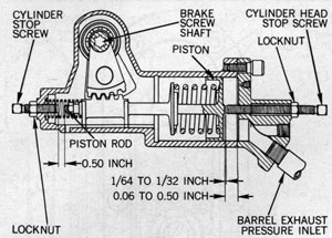
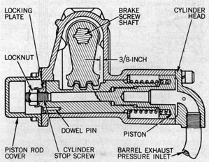
The location of the brake and brake components constitutes the major difference. In Training Gear Mk 6 Mods 0 and 1, the brake actuating cylinder, figure 95, is flange-connected to the breech inboard end of the pump housing (reservoir). In Training Gear Mk 7 Mods 0 and 1, figure 96, the brake actuating cylinder is secured by cap screws to the bottom of the worm housing at the end away from the pump housing (reservoir).
The brake drum in Training Gear Mk 6 Mods 0 and 1 is splined to the main output shaft of the hydraulic unit, while the brake drum of Training Gear Mk 7 Mods 0 and 1 is splined to an extension of the worm gear shaft, figure 31, away from the hydraulic unit. The lower shafting for the training clamp on Training Gear Mk 6 is quite different from that on Training Gear Mk 7 because of the different locations of the brakes. On Training Gear Mk 6,, the horizontal lower shafting of the training clamp extends to the left, parallel with the handwheel drive shafting, and makes connection with the brake band within the pump housing (reservoir). On Training Gear Mk 7, the horizontal lower shafting extends externally to the right from the bottom of the handwheel trunk lower end, figure 81, and across the worm gear housing just above the centering pin assembly. It enters the brake actuating cylinder at the right end of the worm gear housing and goes from there into the housing where the brake band, figure 96, is located. There the end of the clamp output
Figure 95-Automatic Brake Training Gear Mk 6,
Sectional View.
75
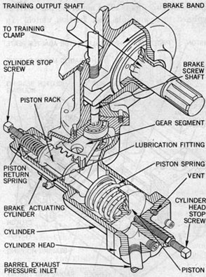
Figure 96-Automatic Brake Training Gear Mk 7, Sectional View.
76
shaft forms a pinion which meshes with a gear above the brake operating screw. When the training clamp is turned, the pinion turns the gear to move the handbrake screw. A slight movement of the screw is sufficient to clamp the brake band to the drum. On Training Gear Mk 6, the hand clamp shafting does not terminate at the automatic brake operating screw but terminates on the opposite lug of the brake band, figure 95.
In each case, automatic operation is similar. Torpedo propelling pressure from the fired tube is transmitted to the automatic brake cylinder which contains a. piston, a piston rack, a gear segment, and a brake operating screw. This pressure or firing force is transmitted to the piston, thence through a piston spring to a piston rack. The spring reduces the shock on the gear teeth; the piston rack transmits linear motion into rotary motion through the gear segment to actuate the brake band clamping screw, figure 96.
In Training Gear Mk 6 Mod 1, pressure is transmitted to the piston through one of four connections to the outside tube barrels. Connection to the center barrel in Training Gear Mk 6 Mod 0 is omitted because firing the center barrel does not tend to slew the saddle. The pipe connections from the tube lead to a manifold outside the lower handwheel trunk and thence to the automatic brake actuating cylinder. The barrel ends of the pipes have check valves which prevent leakage into the nonfiring barrels.
In Training Gear Mk 7, the four pipe connections contain check valves which function to prevent impulse pressure, in the barrel fired, from entering the other barrels. The manifold and piping are slightly different than in Training Gear Mk 6; they are near the brake operating cylinder.
After firing, leakage through a vent, figures 95 and 96, reduces the pressure inside the cylinder and permits the piston spring to return the piston to its normal position, releasing the brake. In Training Gear Mk 6, a special return spring at the opposite end of the cylinder assists return of the piston.
Operation
There are two methods of normal operation of the training gear, power operation and manual operation. Before attempting to train the tube by either method withdraw the centering pin, chapter 3, and fully release the training clamp.
If power is not available turn the handwheels to train the tube manually.
Power Drive. The START button on the controller is pushed in to start the electric motor. The motor should be run for a few minutes before handwheels are turned. The speed selector lever may be in either its HIGH or LOW speed position for power train.
Starting the electric motor automatically starts the auxiliary pump to which it is geared. Figure 97 is a schematic diagram of Training Gear Mk 7 but also is applicable to Mk 6. Fluid under pressure from the auxiliary pump shifts the unloading pilot plunger (1) to its right hand position, to admit pressure to the cylinder of the neutral lock valve and the friction clutch through lines (2), (3), and (4). The neutral lock valve detent plunger thus is withdrawn to permit axial movement of the stroking screw (7), and the friction clutch is engaged to connect the hydraulic motor to the pinion (12). The arrows in figure 97 indicate motions in right train.
Handwheel motion is transmitted to the stroking screw (7) through various shafts and gears. The differential gear (6) , through which the stroking screw (7) runs, is threaded for the screw and is restrained from axial movement. Axial movement of the screw will move the tilt box in the main pump from its neutral position through motion of the crosshead (8), the connecting link, and the trunnion lever (9). Axial movement of the stroking screw (7) is permitted by the sliding spline connection (10).
Fluid flows from the main pump to the hydraulic motor to rotate the output shaft (11) through pinion (12) and gear (13). When gear (13) is rotated, it turns idler gear (14), which rotates differential gear (6) in the same direction as that in which the stroking screw (7) previously was turned. This resets the tilt box to neutral when the handwheels are stopped.
Manual Drive. When the electric motor is stopped, the clutch actuating and neutral lock valve cylinders are vented to the pump housing (reservoir) through the unloading pilot plunger. The friction clutch is disengaged by its spring.
The neutral lock valve detent plunger, actuated by its spring, tends to engage the crosshead (8), and will engage it if the tilt box is at neutral. If response to handwheel motion in either direction is not immediate, the tilt box is off neutral.
77
Figure 97-Training Gear, Hydraulic Diagram.
Handwheel rotation alternately in each direction will drive the tilt box back to neutral and allow the detent plunger to engage the crosshead (8).
With the stroking screw (7) axially locked by the neutral lock detent plunger engaged in the crosshead (8), handwheel rotation is transmitted directly to the output shaft through gears (6), (14), and (13).
The tube can be slewed rapidly or trained slowly, depending upon whether the mechanism is in high or low gear. Right train is limited by the upper train limit stop, left train by the lower.
The brake acts automatically when either the left or right barrels are fired. It is operated
manually to lock the tube at any point within training limits by turning the training clamp wheel.
Maintenance
Inspection. When training the barrels, inspect the training gear for freedom of movement and lost motion. Lost motion should be taken up so that the tube does not jump when firing.
DAILY, inspect to see that parts are protected effectively. Take all necessary precautions to exclude dirt or gritty foreign matter.
WEEKLY, try the fluid level of the hydraulic drive with the petcocks on the sides of the hand-wheel mounting bracket.
78
MONTHLY, open drain and inspection holes in electric motor housing. Excessive oil indicates a leak from the pump housing (reservoir). Inspect for leak; renew faulty oil seals.
QUARTERLY, in Training Gear Mk 6 Mods 0 and 1, remove the inspection plug on the pump housing, on the forward side at the level of the output shaft. Inspect for oil or grease on the brake band; if found report it immediately to the torpedo officer. The source of the lubricant on the brake band must be found and the defect corrected before firing. If the tubes are fired with a slippery brake band, the mount may slew as much as 10 degrees before the torpedo has cleared the barrel.
On Training Gear Mk 7 Mods 0 and 1, the brake unit is accessible through the cover plate at the end of .the worm housing. For the same reasons given for Training Gear Mk 6, the brake unit should be disassembled and inspected quarterly to make sure no oil or grease is on the brake drum or the brake band.
Oil holes should be inspected to see that they are clean and free from paint or other foreign matter. Canvas covers should be examined and renewed where necessary.
Inspect electrical connections to the motor and the overcurrent indicating light. Make sure connections are tight, dry, and in good condition. Be sure not to reverse the motor leads. Inspect all electrical cables visible and repair any with worn, cracked, or doubtful outer sheathings. Check the lamps and circuit of the overcurrent indicating light.
EVERY 18 MONTHS, before refilling the hydraulic system with clean hydraulic fluid, open all covers and access plates and inspect all working parts. If these are corroded badly, or if the housings contain a quantity of rusty sludge, the hydraulic equipment should be overhauled completely.
When working on hydraulic equipment, take every precaution to keep chips or filings from entering the system. Before installing, inspect fittings and threads for slivers. When equipment is open for repairs, see that all parts are covered with a clean tarpaulin when work stops temporarily. Insert wooden plugs in all pipe openings. Inspect pipes for scale, copper oxide, or spelter. See that tubes are wire-brushed and pickled after any annealing, bending, silver soldering, or brazing operation. Inspect for cleanliness the
containers used for filling the system or for storing fluid. Make sure that they previously have not been used for acids, lyes, or other chemicals. Inspect for water in the system by opening low point drains; drain until undiluted fluid comes out. Check for rust caused by excessive water in system. When assembling shafts or valve rods through sealing members, see that they are chamfered, free from sharp edges, burrs, and dirt or other foreign matter, to prevent scoring oil seals. Ascertain that tubing is bent accurately and fitted so that it will not be necessary to spring it into place. See that pipe flanges fit accurately on their seats. Determine that threaded pipe fittings are screwed tightly into place and that tight fit is assured through tinning the male thread and not through the use of sealing compound. Listen for noise in the pump or the motor, which may be caused by air in the system. (Frequently, air can be expelled by opening air vents at high points in the system, where it may be trapped.)
Exercise. The training gear should be exercised after lubrication to prevent jamming of moving parts by an excess of lubricant. WEEKLY, the tube mount should be trained through its entire arc of train.
Lubrication. Only filtered Power Transmission Fluid MIL-F-17111 (NOrd) should be used to fill the hydraulic system. Approximately 20 gallons will be required to fill the equipment to the normal operating level. Before filling, the fluid should be strained carefully through a 200-mesh screen, even though taken fresh from an original container. Fluid should be replenished through the filler hole on top of the handwheel mounting bracket. if the level has fallen below the lower petcock on the side of the handwheel mounting bracket.
Remove the plug at the top inspection cover of the pump housing (reservoir) to vent the lower system before pouring the fluid. Continue pouring until fluid appears; replace the plug. The system can be filled faster by first filling the pump housing (reservoir) through one of the cover plates in its top and then completing the fill through the top of the handwheel mounting bracket.
When fluid runs out of the lower petcock, close it. When fluid runs out of the upper petcock, the proper fluid level has been reached; close the upper petcock and replace the plugs securely.
79
While replacement of fluid should not be necessary unless grit, lint, or other foreign matter has been allowed to enter the equipment, fluid must be replenished if a weekly routine check shows that the level has fallen below the lower petcock on the handwheel mounting bracket.
Training Gear Mk 6 Mods 0 and 1 may be drained of hydraulic fluid by opening the petcock in the bottom of the sludge pot at the bottom of the lower trunk assembly and by removing the drain plug from the bottom of the pump housing (reservoir).
Training Gear Mk 7 Mods 0 and 1 may be drained by removing the plugs in the clamp output shaft housing and the bottom of the pump housing (reservoir).
To flush out the hydraulic system, fill it with Diesel Fuel Oil MIL-F-16884 (Ships). Train the tube continuously for 10 minutes under power. Immediately after shutting off the electric motor, drain the hydraulic system completely and refill with hydraulic fluid.
CAUTION: To insure that no air pockets exist, run the electric motor a few
minutes and again check the fluid level.
In addition to parts which are lubricated by fluid from the hydraulic system, there are other points of lubrication. DAILY, or after 4 hours of operation, training worm thrust bearings should be lubricated. These can be reached by removing the pipe plugs in the top of the worm housing. Training worm bushings, too, should be lubricated at this time.
WEEKLY, or after 30 hours of operation, lubricate the automatic brake.
MONTHLY, or after 120 hours operation, brake shaft bearings should be oiled lightly and hand-wheel grips should be greased through their lubrication fittings.
SEMIANNUALLY, or after 720 hours operation, the electric motor should be cleaned and lubricated as follows:
1. Wipe the motor, grease cups, fittings, and drain plugs free of all dirt.
2. Remove the grease drain plugs and clean the drains of old grease by probing with a clean tool.
3. Remove the grease cups and clean the cups and receptacles of old grease.
4. Clean the grease inlet passages of old grease by probing with a clean tool.
5. Start the motor and run for 15 or 20 minutes to warm thoroughly the old grease in the bearings.
6. Stop the motor and with a clean tool probe any old grease forced into the inlet passages and into the drain.
7. Start the motor and allow it to run continuously during steps 8 through 10.
8. Fill the grease cups and receptacles with fresh, clean, authorized lubricant and screw the cups all the way down on their receptacles. Use two cups of grease for each bearing of the motor.
9. Remove the grease cups and allow the motor to continue running for 15 minutes or until all excess grease in the bearing housings has been forced out through the drain and inlet passages through the rotating parts of the bearings.
10. Replace all grease cups and drain plugs. Screw the grease cups all the way down on their receptacles.
11. Stop the motor and wipe off all excess grease.
The pump drive gears are lubricated by filling the gear case of the electric motor to the level of the lowest gear pitch line.
For lubrication intervals, lubrication specifications, and lubrication check points, refer to chapter 12.
Preservation. Cleanliness throughout the system is very important. When necessary to clean the filter cartridge, take out the four socket-head cap screws holding the oil filter cover to the oil filter support bracket. Remove the cover and slip out the cartridge. After cleaning, reassemble in reverse order. If it is desired to run the equipment while cleaning the filter cartridge,1/4 inch pipe plugs should be screwed into the two tapped holes in the filter mounting bracket. Remove these plugs before reassembling filter. Carefully follow the detailed lubrication instructions in chapter 12 to prevent corrosive effects of the sea and varying weather conditions as well as the wear that comes through friction. Materials for lubrication, corrosion protection, and hydraulic power transmission have been authorized for these units and should be used as directed.
Operating Instructions
1. Check oil level at petcocks on the handwheel mounting bracket.
80
2. Release centering pin and training clamp.
3. Turn handwheels alternately in each direction to see that tilt box is in the neutral position with detent plunger engaged before turning on motor. The motor should be started at no greater than idling load.
4. For power operation, push START button on the controller and allow motor to run a few minutes.
5. Shift speed selector lever either to HIGH or LOW, depending on desired speed of train.
6. Rotate wheels forward for right train, backward for left train.
7. For manual operation, shift into LOW gear and follow the preceding directions except step 4; do not start electric motor.
Operating Precautions.
1. Be sure to release hand clamp ALL THE WAY.
2. Rotate handwheels alternately in each direction before starting motor. Never start motor until tube trainer is at his station.
3. Watch overcurrent indicating light. If it signals red, slow down handwheel rotation, shift into LOW if in HIGH gear, or push STOP button on controller and operate manually.
4. Be alert to any abnormality of operation such as excessive lag or lost motion, irregularity of motion, noises such as popping, sputtering, grinding, hydraulic chatter, or hammer. Report, or correct in accordance with instructions in table 2.
Table 2 TROUBLE ANALYSIS
Symptom
Possible Cause
Remedy
MANUAL OPERATION
1. Mount trains, but there is excessive lost motion in handwheels.
1. Neutral lock valve detent plunger fails to engage. *
1. Turn handwheels one way or the other until neutral lock plunger snaps into place.
2. Time for neutral lock valve detent plunger to snap into place is excessive.
1. Sluggish action of neutral lock valve detent plunger.
1. Check action of neutral lock valve detent plunger as follows: a. Start electric motor and train tube mount by power for about a minute. b. Stop training and let electric motor run for another minute with handwheels and mount at rest. c. Stop electric motor and wait 45 seconds. d. Turn handwheels. (Mount should train manually.)
See footnotes at end of table.
81
Table 2 TROUBLE ANALYSIS-Continued
SymptomPossible CauseRemedy
MANUAL OPERATION-Con.
3. Neutral lock valve detent plunger takes more than one minute to engage.
1. Unloading valve is not functioning properly.
1. Check for defective unloading valve spring as follows: a. Drain fluid from hydraulic system, as described under Lubrication. b. Remove top access cover from pump housing (reservoir). c. Take out unloading pilot plunger stop from auxiliary pump rear end or valve plate. d. Pull out unloading valve pilot plunger. Fish out unloading valve spring; if broken, insert new one. 2. Insert unloading valve plunger and test its action to see that it does not stick. 3. Screw unloading plunger valve in place. 4. Fill pump housing (reservoir) to a level flush with top of auxiliary pump. 5. Check action of neutral lock valve detent plunger by starting and stopping electric motor as described under Remedy, Symptom 2.
4. Handwheels cannot be rotated.
1. Brake is set
1. Check to see that centering pin is released and that training clamp hand-wheel is turned as far counterclockwise as it will go. If handwheels still cannot be rotated, rotate them in opposite direction.
5. Handwheels will rotate in one direction.**
1. Failure of clutch sure to be released.
1. Be pressure that unloading valve is releasing pressure on clutch by performing Remedy, Symptom 3.
6. Handwheels still locked
1. Brake band locked.*** 2. Clutch springs broken.
1. Check for leakage in internal fittings of electric motor as follows: a. Drain off oil as described under Lubrication. b. Remove top access cover from pump housing (reservoir). c. Refill pump housing (reservoir) to a level no more than 1/2 inch up from bottom of auxiliary pump. d. Start electric motor. 2. Check auxiliary lines and flanges of the main transmission lines.
2. Pressure is insufficient to open relief valve.
1. Check to see if a forceful stream of oil is flowing from the side of auxiliary relief valve away from the main pump.
3. Motor leads are reversed
1. Check rotation of the motor. It should be counterclockwise (looking at the motor from the fan end.)
2. Handwheels tend to "motor".Δ
1. Excessive binding between stroking screw and differential nut.ΔΔ
1. Check for binding by performing Stroking Screw Friction Test, page 84. 2. Correct binding according to the instructions under Adjustment, Stroking Screw, page 86 and Adjustment, Worm Gear Housing, page 26.
3. Leakage
1. Threaded fittings are not tightened properly.
1. Tighten.
2. Crossed threads in fitting.
2. Screw properly; if threads are damaged, replace fitting.
3. Improperly fitted or torn gaskets.
3. Refit or replace.
4. Distorted, scored, or lightly scratched sealing sleeves or oil seals.
4. Replace.
5. Ends of tubing improperly flared; not cut square before flaring, or not annealed after flaring.
5. Replace or anneal improperly, wire brush, and pickle.
See footnotes at end of table.
83
Table 2 TROUBLE ANALYSIS-Continued
Symptom
Possible Cause
Remedy
POWER OPERATION-Con.
3. Leakage-Continued
6. Flanged joints not seating squarely.
6. Aline properly.
7. Worn or scored valves.
7. Replace valve.
8. Worn or scored pistons in pump or motor.
8. Replace pistons. Rebore cylinders and replace with new pistons of proper diameter.
9. Worn or scored valve plates in pump or motor.
9. Regrind or replace.
10. Copper tubing cracked or split.
10. Replace.
11. Wrong size tubing or fittings.
11. Replace with tubing or fittings of proper size.
12. Brazing which is porous or does not adhere in spots.
12. Clean and rebraze.
13. Porous casting.
13. Replace with flawless casting.
* Failure of neutral lock valve detent plunger to engage is not serious. It has no effect on power operation nor on manual operation other than to cause excessive lost motion.
** Handwheel travel in the other direction is probably limited by a limit stop.
*** This is an exceedingly rare occurrence.
Δ Motoring is observed when the tilt box is off neutral. The tube mount starts training by itself and continues until the handwheels are stopped forcibly or power is turned off.
ΔΔ Binding may be caused by corrosion, or scoring or galling of parts, but usually is caused by improper shimming of the unit at assembly.
Tests
Installation Tests. Upon installation, the following tests should be made:
1. Completely check the unit. All mechanisms should be examined after shipment for possible damage.
2. See that all parts are clean and well lubricated. Give particular attention to the training worm and training circle (as described in chapter 3).
3. See that the hydraulic drive is filled with suitable fluid as outlined under Lubrication; fluid specifications must be in accordance with lubrication instructions and charts, chapter 12.
4. After assembly of all components, withdraw centering pin and set the upper training gear limit stop as prescribed under Adjustment, page 86.
5. Check all electrical connections. See that fuses are in place, that controller, pushbutton, and overcurrent warning stations are complete and ready for use, and that 440-volt, 60-cycle, alternating current supply is connected to the controller and motor.
6. Check the direction of rotation of the electric motor (counterclockwise from the fan end).
7. See that the torpedo tubes are fully loaded, either with five torpedoes or with an equivalent weight; allow approximately 3850 pounds for each torpedo.
84
Tests for Creep. Check the electric hydraulic drive for "creep" as follows:
1. While the mount is at rest, with the power off, engage the neutral lock valve detent plunger by rotating the handwheels alternately in each direction until immediate train response is noted in both directions without lost motion.
2. After the plunger engages, release the handwheels and turn on the power.
3. While the mount is being trained in power drive, cut off the power and continue by hand.
4. Without reversing the direction of rotation, stop the handwheels in line parallel to the deck. Attach a cord to the one which would rise if rotation were continued and secure the other end of the cord without slack to a 1-pound weight resting on a flat surface below. Then turn power on. If the handwheels turn, lifting the weight, creep is present.
Mount in train should be in the same direction and proportional to speed of handwheel turning at all speeds within rated capacity.
A force not greater than 10 pounds on one hand-wheel handle should be sufficient to train the loaded tubes in power drive under all conditions; a force not greater than 25 pounds should be sufficient in manual drive, if the tube mount is level.
The training limit stops should stop train, without undue shock, while the mount is being trained at full speed in HIGH gear; the stops should not prevent immediate reversal at full speed.
The loaded tube on a level base should train through a full arc of 180 degrees in 32 seconds, starting from rest, if the atmospheric temperature is summer like.
The operation of the electric hydraulic equipment should be smooth and free from excess noise and vibration at any speed. Continue tests for one-half hour; note atmospheric temperature both before and after the tests. Train tube mount manually and under power at all speeds up to the stops and away from them.
Under winter conditions, note particularly the effect of lower temperatures on the action of the equipment.
Report the result of the tests to the Bureau of Ordnance. The report should include the atmospheric temperature, the designation of oil used, and the oil pressure. Other items to be covered in the test report are electrical input under various conditions of operation, speed of train, ease of
train, effect of cold weather (if applicable), action of the equipment, and serial numbers of the torpedo tube, hydraulic unit, electric motor, and controller.
For Training Gear Mk 7 Mods 0 and 1, obtain hydraulic fluid pressure as follows: train the tube to the stowing position and engage the centering pin. Install a 1500-pounds-per-square-inch hydraulic pressure gage with a 1/4 inch International Pipe Standard nipple in one of the two gage connector adapters (see BuOrd dwg 297210). Do not use an air pressure gage because oil would be forced into the gage by this test. Turn power on. Hold down the START button as the test will overload the equipment and would otherwise trip the overload relay. Rock the handwheels back and forth to see which direction of rotation causes a positive deflection of the gage. Turn the hand-wheels in this direction until a maximum pressure is observed. Release the START button; record the maximum pressure and the direction of rotation. Turn the handwheels back and forth until the neutral lock valve plunger is engaged. Turn power off and attach the gage to the other gage connector adapter. Repeat the test with hand-wheel rotation in the opposite direction. Because the motor is overloaded, work fast. The motor should not be on for more than 10 seconds for the test.
Test pressure on Training Gear Mk 6 Mods 0 and 1 by other means, if practicable.
Stroking Screw Friction Test. As described in table 2, if there is excessive binding of the stroking screw and differential nut, and electric power is turned on while the tilt box of the main pump is off neutral, the tube will train by itself.
To determine whether binding is causing this condition, proceed as follows:
1. Remove the pump housing (reservoir) from the tube.
2. Remove its top access cover.
3. Remove the neutral lock valve detent plunger stop from the bottom of the neutral lock valve and fish out the spring.
4. Remove the neutral lock valve plunger.
5. Remove the crosshead link pin.
6. Set down the unit access cover.
7. Insert bar for wrench in coupling hub on shaft and then turn shaft to apply torque on coupling hub until the crosshead is lifted to the uppermost position.
85
8. Remove the wrench.
9. Start the coupling hub by manual rotation and see whether the weight of the crosshead pulls the screw down. If it does, friction between the nut and stroking screw is eliminated as a cause of "motoring". If motoring exists, refer to Adjustment, Stroking Screw, page 86.
Automatic Brake Test. The only effective way to test the firing brake is to fire a live or dummy torpedo from a wing barrel under conditions which will impose the greatest load upon the brake. To obtain these conditions, load a wing barrel. Approach the firing train angle in power drive, training in the same direction as the barrel which is to be fired (i. e., if a left wing barrel, train left). 'While still turning the handwheels, shut off electric power and continue to the firing train angle manually. Handwheel rotation must not be reversed while approaching the firing position since this would engage the neutral lock valve plunger detent, and result in a decrease of the firing load applied to the brake. The saddle should not move more than one-quarter degree with respect to the stand, when the tube is fired.
To obtain the most unfavorable or severe conditions for the brake (and, therefore, those best for the test), the training gear should be well lubricated, especially the training worm threads, and the atmosphere should be warm enough to insure the fluidity of the lubricant.
Adjustment
Safe Firing Angles. Before the limit stops are set, safe firing angles of the tubes (with respect to ship structure) can be determined by referring to figure 98.
A torpedo may be fired without excessive danger of striking own ship structure if at any given position (L) along the extended wing barrel centerline, any possible interference point is farther away than the horizontal (H) or vertical (V) distance given in figure 98.
The H and V values are considered adequate if the torpedo is fired at the instant the ship is level and that the ship is on the up roll and that the roll does not exceed 30 degrees, 15 degrees up and down. Figure 98 gives minimum clearance firing values for wing barrels only.
Figure 98-Safe Firing Angles.
86
Figure 99-Limit Stop Adjustment.
Limit Stops. figure 99. The limit stops may be set incorrectly for the particular shipboard installation. If this is so, it is necessary to reset them aboard ship. Before attempting any adjustments, drain approximately seven gallons of oil from the limit stop housing. Then train the tube
mount to the allowed limit of train to the left. Remove one traveling nut guide cover to observe that the traveling nut engages the lower (left train) limit stop. If the traveling nut is not engaged, remove the other traveling nut guide cover. Rotate the traveling nut to engage the lower (left train) limit stop. Never change the position of the lower limit stop. Install one traveling nut guide cover.
Train the tube to the allowed limit of right train and adjust the upper (right train) limit stop as follows: First, remove the traveling nut guide cover, figures 84 and 99. Straighten out the bent-over portions of the lockwasher. Holding the shaft from turning, unscrew the limit stop cap. Slide back this cap, remove the key, then slide back the limit stop adjustment. The upper limit stop may then be rotated freely on the shaft. Engage the jaws of the limit stop with the traveling nut. Slide the limit stop adjustment in place, insert key, and screw limit stop cap to limit stop. Punch-lock the lockwasher to hold the assembly in place. Recheck limit stop positions by training the tube in both directions.
Stroking Screw. Improper shimming when installing the electric hydraulic equipment can cause minor distortions in housing members (particularly that which encloses the stroking screw and sliding spline), which will result in the binding of closely fitted control parts with consequent "motoring" of the handwheels, as described in table 2.
Therefore, besides the shimming described under Adjustment, chapter 3, particular attention should be given to the assembly instructions, page 90. A nominal shim thickness of 0.10-inch is required at the four 5/8-inch bolts which secure the pump housing (reservoir) to the bracket under the left barrel, figure 100. On Training Gear Mk 7 Mods 0 and 1, there is a nominal shim thickness of 0.03 inch for the joint between the lug on the lower gear housing and the worm housing cover plate. The shim should be fitted to secure proper alignment and to prevent any distortion of the equipment when the bolts are tightened. Shims also are furnished for the point of suspension where an integral lug on the pump housing (reservoir) is bolted by two 1-inch bolts to the bracket on the left barrel. The 7/8-inch holes in the brackets should be reamed to take 1-inch bolts.
87
Matching holes should be bored in the lug upon positioning.
Shims, figure 100, are provided for fitting the spider of the limit stop housing to its four points of support on the T-guides of the center and left-center barrels.
Relief Valves (figure 101). To adjust the tension of the main relief valve springs, first drain hydraulic fluid from the system, and unbolt the main relief valve cover which protrudes from the end of the pump housing (reservoir) farthest away from the output shaft. Increase or decrease the tension by tightening or loosening the spring adjusting screw (two in Training Gear Mk 7 Mods 0 and 1). Main system lines and valves should operate at a pressure of 800 pounds per square inch in Training Gear Mk 6 Mods 0 and 1, and a maximum of 960 pounds in Training Gear Mk 7 Mods 0 and 1. Auxiliary lines and relief valve should operate at a pressure of 100 pounds in the Mk 6 Mod 0; 70 pounds in Training Gear Mk 6 Mod 1; and approximately 75 pounds in Training Gear Mk 7 Mods 0 and 1. For determining pressure, refer to Tests, page 83. Adjustments must be made so that the system operates below maximum pressure limits with enough spring tension to reseat valves when pressure is off; if these conditions cannot be met, replace the faulty valve spring.
Figure 100-Stroking Screw Adjustment.
Figure 101-Main Relief Valve Adjustment,
Training Gear Mk 7.
The auxiliary relief valve spring is adjusted in the same manner as the main relief valve, figure 101. The pump housing (reservoir) must be opened for access; the valve plate is in the rear of the unit.
Automatic Brake, Training Gear Mk 6 Mods 0 and 1 (figure 102). The automatic brake is adjusted prior to shipment. However, the ability of the brake to prevent undue whip of the mount when a torpedo is launched from a wing barrel should be proved during test firings of the torpedo tube; readjustment of the brake may be required at that time. Also, it may be necessary to adjust the brake in service.
To check the adjustment of the automatic brake:
1. Back off the training clamp wheel on the handwheel trunk its full travel.
2. Disconnect the union that joins the manifold to the brake cylinder head.
3. Remove the cylinder head.
4. Push the piston in by hand to take up lost motion.
5. Scale the distance from the face of the piston to the face of the cylinder; it should be between 0.06 and 0.50 inch, figure 102. If the distance is correct (with lost motion removed), no change of adjustment is required.
6. Replace the cylinder head on the cylinder.
88
Figure 102-Automatic Brake Mk 6 Adjustment.
7. Gradually set up on the cylinder head adjusting screw to the point at which the brake begins to hold.
8. With the training gear in manual drive, attempt to turn the handwheels while the screw is being turned to determine whether the brake is free. or set.
9. Back off the cylinder head adjusting screw just enough to release all drag on the brake drum (between one-quarter and one-half turn of the screw, 1/64- to 1/32-inch of travel, figure 102) to free the brake.
10. Lock the screw with the locknut.
11. Set up the stop screw until it contacts the piston rod (or until the head of the screw hits the locknut).
12. Back off the stop screw 1/2 inch and lock. The brake mechanism now should operate properly, provided there is no lubricant on the brake drum. Never operate with oil or grease on the brake drum.
Automatic Brake, Training Gear Mk 7 Mods 0 and 1 (figure 103). The brake must be adjusted so that, when in the released position, the brake band will be compressed by a slight movement of the piston. Total movement of the segment is so restricted by the walls of its chamber that the segment's initial position must be correct.
To adjust the brake:
1. Remove the segment cover.
2. Rotate the segment by hand in the direction it is moved by the rack to tighten the brake band (counterclockwise from above) to see whether the brake is set within the limited movement permitted by the brake cylinder housing.
3. At the position where the brake starts to set, locate the segment so that the lug adjacent to the outer tooth is not more than 3/8 inch from the chamber wall on the piston side, figure 103.
4. If the segment must be moved a greater distance from the wall to begin to set the brake, remove the segment.
5. Turn the brake screw until the thread is free.
6. Reassemble the brake screw with a new thread adjustment.
7. Install the segment in a different manner on the spline until a combination is found that places the segment within the zone specified in step 3.
8. Remove the piston rod cover.
9. Free the lockwasher.
10. Back off the nut on the piston rod and pull the locking plate free of the dowel pin in the end of the rack.
11. Rotate the piston rod clockwise. Since the piston rod is threaded to the rack and the rack is keyed to the cylinder, this rotation tends to set the brake.
12. Turn the piston rod to the point at which the brake begins to hold.
13. Rotate the handwheels in manual drive to see whether the brake is free or holding while the brake screw is being turned.
14. Turn the piston rod in the opposite direction just enough to release all drag on the brake drum. Do not go beyond the point at which the brake is fully released.
Figure 103-Automatic Brake Mk 7 Adjustment.
89
15. Reassemble the locking plate, lockwasher, nut, piston rod cover, and segment cover.
Worm Gear and Shaft. When connecting the main output shaft with the worm gear shaft, make sure they are aligned properly and the flange connection is seated properly. For important adjustments of the worm gear, refer to Adjustment, chapter 3 and figures 34 and 35.
Disassembly and Reassembly
Drive Motor. To remove the drive motor, disconnect electrical cables from their terminals; tag each of them so they will not be reversed when the motor is reinstalled. Drain out all lubricant from the gear case by removing the plug in the bottom of the motor mounting flange. Take out the socket head cap screws and stud nuts holding the motor mounting flange to the main hydraulic pump housing flange. Using a rope sling, slip the motor back off the rabbet.
To disassemble the motor, first remove it as described in the preceding paragraph. Finally, referring to BuOrd dwg 268221, remove motor gear 279160-5. Any further disassembly should be apparent from the drawing. Reassemble in reverse order of disassembly.
Power Drive Components. Power drive components enclosed in the pump housing (reservoir) can be removed as a unit from the housing. First, completely drain the equipment as described under Lubrication. Remove the oil filter assembly as a unit from the housing as follows: Referring to BuOrd dwgs 279154 and 279278, remove top access cover 279212-2 from the pump housing (reservoir). Disconnect the two pressure lines (2792298 in BuOrd dwg 279227, and 279169-10 in BuOrd dwg 279155), one from auxiliary pump to the oil filter and the other from the oil filter to make-up valve. Now take out the four socket head cap screws holding the filter mounting bracket to the supply tank and pull assembly clear of equipment.
Next remove front inspection cover 279212-4 (BuOrd dwg 279154, sheet 1) and the hydraulic motor access cover from the pump housing (reservoir), uncouple the main transmission lines between the hydraulic pump and the hydraulic motor. In Training Gear Mk 6, take out the main relief valve spring housing (279166-6 in section BB, sheet 2, BuOrd dwg-279155) on the left hand or hydraulic motor access cover side. Remove connection link pivot pin 279169-5 (BuOrd dwg
370563 O-56-7
279155, sheet 2) and uncouple all auxiliary lines. Remove the 12 socket head cap screws holding the pump mounting flange to the pump housing (reservoir) . Ease the unit. assembly out of the pump housing (reservoir) with a rope sling.
Handwheel Mounting Bracket and Components. The order of disassembly and reassembly of this subassembly is apparent from BuOrd dwg 279151. No backlash should be permitted in bevel gears 279184-5 and 279184-7 when reassembling in reverse order of disassembly.
Handwheel Trunk and Components. Disassembly routines for Training Gear Mk 6 are apparent from BuOrd dwg 279152, and for Training Gear Mk 7 from BuOrd dwg 297208.
Before attempting to mount the equipment, secure the pump housing (reservoir) assembly in place, page 90. Then set in place gasket 2792016 (also 279201-4 for Training Gear Mk 6). Now, using rope slings, carefully lower equipment between the center and left-center barrels. Turn handwheels so that the splined hole of the sleeve coupling (279206-4 for Training Gear Mk 6, and sleeve coupling 279199-6 for Training Gear Mk 7) is aligned with the drive gear train rig shaft in the lower trunk gear housing. Also rotate the training clamp so that the miter gears 279206-3 properly mesh. Insert shims described under Adjustments, at the four points of support for the spider of the limit stop housing on the T-guides of the center and left-center barrels. Ease the equipment into place and bolt. down to the lower trunk gear housing.
Lower Handwheel Trunk. To remove this subassembly from the equipment, first dismount the handwheel trunk and limit stop assembly as described in the preceding paragraph and under Adjustment, Limit Stops. Take out the cap screws holding the lower trunk gear housing to the worm housing cover plate. Remove the cap screws holding the differential screw sleeve housing (279041 in BuOrd dwg 279153 for Training Gear Mk 6, and 29719-1 in BuOrd dwg 297277 for Training Gear Mk 7) to the brake housing in Training Gear Mk 6 and to the training clamp output shaft housing in Training Gear Mk 7. Using a rope sling, ease unit away from the brake or the output shaft housing; take care not to damage the splined extension of the stroking screw (279214-1 in BuOrd dwg 279154 sheet 2, for Training Gear Mk 6, 279214-8 in BuOrd dwg 297206 for Training Gear
90
Mk 7 and 297270-1 in BuOrd dwg 297278 for Training Gear Mk 7 Mod 1). Disassembly of the subunit itself is apparent from BuOrd dwgs 279153, 297277, or 297209. Reassembly is in reverse order of disassembly. Make sure there is no backlash in the pair of bevel gears 279205-2 and 279206-1.
Pump Housing (Reservoir). Place jacks under the equipment or use a rope sling under it around the left barrel. Before removal, drain fluid from the handwheel trunk section and from the pump housing (reservoir) . Referring to BuOrd dwg 273272, detach equipment as follows: Detach manifold union at cylinder head (279193-2) in Training Gear Mk 6. Remove bolts which secure pump housing (reservoir) to roller bracket (273263-1) and barrel bracket (160861-10) as shown on section W-W. Remove eight bolts at flange which join pump housing (reservoir) to worm shaft housing. Remove bolt through lug on lower trunk gear housing (279203-1) which joins this housing to worm housing front cover plate. Now the assembly is ready to be moved out. Keeping it supported, ease it out; take special precaution to keep the splined shaft (279220-3) in line to prevent any possible chance of distortion. All shims removed should be set apart and clearly identified to permit ready reinstallation in the positions from which they are removed.
When mounting the equipment, place it so that the output shaft is in line with the training worm shaft, but at a lower level so that the pump housing (reservoir) will pass beneath its mounting bracket on the left wing barrel. Next, move it toward the worm shaft until clear. Then, lift until the output shaft lines up with the worm shaft horizontally as well as vertically. The end of the output shaft will pass up through a channel cut for that purpose in the end flange of the worm bracket. Engage the output shaft with the worm shaft and make up the flange joint. A. support for the supply tank is provided by the mounting bracket on the left barrel. Four %-inch bolts are furnished for securing the pump housing (reservoir) to the bracket; a nominal thickness of 0.10 inch of shims is required between the two parts.
Main Pump. After removal of power drive components as a unit, disconnect auxiliary pump. Further disassembly of Training Gear Mk 6 hydraulic pump can be accomplished with the aid of
BuOrd dwg 279151, and of Training Gear Mk 7 pump with BuOrd dwg 297281. Reassemble in reverse order of disassembly.
Auxiliary Pump. To disassemble, after removing power drive components, remove auxiliary pump as a unit by removing auxiliary pump gear cover 279172-4. Take out the four socket-head cap screws which hold the auxiliary pump mounting plate to the main pump housing and pull the pump free. Further disassembly of auxiliary pump and connecting valves for Training Gear Mk 6 is apparent from BuOrd sectional assembly dwg 279155, and in BuOrd dwg 297212 for Training Gear Mk 7. Reassembly is in reverse order of disassembly.
Stroking Screw Assembly. Referring to BuOrd dwg 279154, remove the top access cover 279212-2 and the hydraulic motor access cover 297225-1. Remove the neutral lock valve detent plunger stop 279215-4 and withdraw the lock plunger 279221-9. Take out the crosshead guide 279223-10. Remove the pin 279169-5 by which the crosshead link 279221-5 is secured to the trunnion lever 279169-3. The neutral lock valve housing 279213-1 can be removed to provide lateral freedom for the inner end of the stroking screw.
Turn the pump housing (reservoir) on its side with the output shaft vertical. Remove the screws securing the gear cover to the supply tank. Lift the brake housing (output shaft housing in Training Gear Mk 7) and attached gear cover; be very careful to prevent the application of bending loads to the stroking screw as it emerges from the pump housing (reservoir). Remove the bearing retainer 268582-1 or -2 and take the bearings off the stroking screw. If the threads are uninjured, the screw now may be turned until free of the differential gear. If the threads are damaged, disassembly of the gear cover output shaft housing is required to permit removal of gear and screw as a unit. Reassembly is in reverse order of disassembly.
Hydraulic Motor. Drain fluid from equipment as described under Lubrication. Remove oil filter as a unit as described under Power Drive Components, page 89. Remove front inspection cover 279212-4, clutch inspection cover 279212-3, and hydraulic motor access cover 279212-1 from the pump housing (reservoir). Take out the six socket-head cap screws which hold the hydraulic
91
motor angle box 279177-1 or -2 to the inside flange support of the pump housing (reservoir). Disconnect the auxiliary pressure line from the side of the hydraulic motor angle box and the main transmission line flanges from the hydraulic motor valve plate 279181-1. Ease the hydraulic motor out of the pump housing (reservoir) as a unit. Disassembly of Training Gear Mk 6 itself is apparent from BuOrd sectional assembly dwg 279157, and Training Gear Mk 7 from BuOrd dwg 297211. Reassembly is in the reverse order of disassembly.
Automatic Brake, Training Gear Mk 6. To disassemble the brake mechanism to inspect the brake band, proceed as follows: Drain the oil from the pump housing (reservoir). With the pump housing (reservoir) resting on a level surface, block up under the brake housing so that it will be supported when separated from the pump housing (reservoir).
Referring to BuOrd sectional assembly dwg 279154, sheet 2, section C-C, remove the 16 cap screws which join the pump housing (reservoir) and the gear case cover 279210-1. Separate the two a distance of 31/2 inches. With the neutral lock valve plunger stop removed, another couple of inches of separation can be gained. Removing the crosshead guide will allow more separation (7 inches or more), if necessary. This is done by removing three cap screws 279225-33, shown in section F-F, sheet 1, BuOrd dwg 279154) which hold the crosshead guide 279223-10 to the neutral lock housing. As the units are moved apart, give enough support to the gear case assembly so that the stroking screw will not be distorted.
Remove two cap screws 279225-2 (section A-A) and gear washer 279220-5, and detach output gear 279217-4 from output shaft 279220-3. Remove intermediate gear 279217-5 with assembled bearings. Remove 18 cap screws 12-Z-51-64, with lockwashers, which join gear case cover and brake housing. Using a maul of soft material to cushion the blows, drive the output shaft through the bearings. This will remove the brake assembly and brake housing intact.
To remove the brake from its housing, remove six cap screws with lockwashers from the open end of the output shaft to release the output shaft oil seal retainer. Bend back lugs on star washer and remove nut, using socket wrench. Then remove brake clamp assembled with brake drum and output shaft.
During reassembly, make sure all parts are free of grease and oil. It may be necessary to relieve the output shaft to drive it back through the bearings. However, no looseness between shaft and bearings is permissible. The proper fit is one which is just tight enough to require the use of a soft maul to drive the shaft through the bearings. Therefore, be careful in grinding down the shaft so that the amount of metal removed is no greater than that necessary to obtain such a fit. Use a small piece of shim stock to protect the oil seal when locating the output shaft oil seal retainer. Assembly is in reverse order of disassembly. With the brake reassembled, it will be necessary to make the brake cylinder adjustment described under Adjustment. If the brake band has been replaced, compressed air at 80 pounds-per-square-inch pressure, blown into the cylinder about 15 times in short blasts, will help to seat the new brake band and correct any tendency toward sticking, so that the brake will release quickly.
Automatic Brake, Training Gear Mk 7. Due to the different location of this brake, disassembly is much less complicated. A short study of the preceding paragraph is recommended, however, for general procedures and precautions where they apply. Both assembly and disassembly procedures become obvious from a study of BuOrd dwg 315151, section V-V. Reassembly is in reverse order of disassembly.
Worm Gear Drive. Carefully follow instructions in chapter 3 for removal, disassembly, and reassembly of saddle, noting reference to the paragraph on Adjustment, and in chapter 7, disassembly and reassembly instructions relating to the disconnection of the lower end of the torpedo course indicator shaft.