The location of the Torpedo Director Mk 27 Mods 1 to 9 varies on modern destroyers. The
location depends upon the number of directors used on the ship. On destroyers with one torpedo
director, it is located on the fore and after centerline, forward of the Gun Director Mk 37. On
destroyers with two torpedo directors, one director is located on each of the port and starboard
wings of the bridge.
The following procedure is recommended when installing the torpedo director aboard ship:
1. From the BuShips plans of the bridge, determine the exact location for the installation of the
torpedo director.
2. Check the base ring (foundation ring welded to the deck) to see that the plane of its machined
surface is parallel to the reference plane within the allowable tolerance of approximately 6
minutes of arc. Also check to see that the eight mounting holes have been properly prepared.
3. Before hoisting the torpedo director into its proper location, examine it, so that a director
destined for the starboard side will not be installed on the port side or vice versa. This is done
by examining the name plate or the position of the transformer switch on the stand. The
transformer switch should always be on the inboard side when the torpedo director is sighting
forward. See figures 26 and 28.
Caution. Before hoisting the director from the dock or truck to the ship's bridge, make sure the
hoisting sling is properly placed around the bottom of the director case. Do not attempt to hoist
the director by attaching the sling to the projecting handwheels or to the telescope pivot.
4. Secure the director to the base ring on the bridge deck.
5. Remove the terminal board cover from the torpedo director stand.
6. Pass the ship's cables through the six terminal tubes in the base of the stand.
7. Wire up the ship's wires to the terminal board as indicated on the wiring diagram, BuOrd
Dwg 168050, for the Torpedo Director Mk 27 Mods 4 and 5. Navy lead designations for the
various wires are listed on BuOrd Dwg 249085.
8. Seal the ship's cables in the terminal tubes in accordance with BuOrd Dwg 137593 in all six
terminal tubes in the base of the director stand. See figure 66.
Initial Alignment
After the torpedo directors are installed aboard ship, they are aligned so that when the directors
are pointing directly forward the true and relative target bearing dials will indicate zero
degrees and when pointing aft, the dials will indicate 180o. The torpedo course check dials will
also indicate zero and 180o for these conditions. The following procedure is recommended for
initial alignment of the torpedo director:
1. Set all the dials of torpedo director to zero. This is done by turning the various hand cranks
until the dials indicate zero.
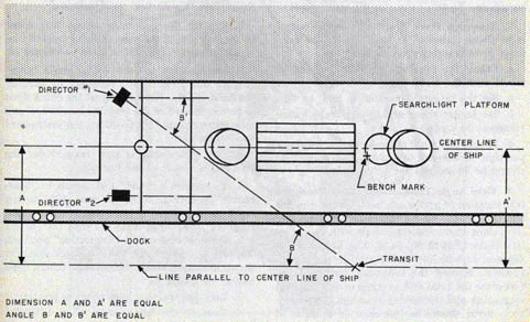
2. On the dock and alongside of the ship, establish a fore and after line with a transit. See figure 84. The procedure involved for doing this is described in OP 762.
3. Train the torpedo director by turning the training handwheel until the line of sight of the
telescope is on the sight of the transit.
4. Check the reading of the true and relative target bearing dials to see that they indicate the
bearing of the transit. The torpedo course check dials should also indicate this bearing. If the
dials are off, set them correctly by using the micrometer adjustment on the Dsk shaft.
Note: The above procedure is only used after initial installation of the torpedo director or when
the bench marks are not available.
86
INSTALLATION-DIRECTOR
With the torpedo director properly lined up, bench marks can be established which will serve
as a reference for any future alignment of the director. On ships with two torpedo directors, the
location of the bench mark is selected aboard ship so that it will serve for both directors, the
bench mark is placed on some permanent structure which is approximately on the ship's fore
and after centerline toward the after part of the ship. See figures 3 and 85. The following procedure is recommended for establishing the bench mark:
1. Pick a suitable location for the bench mark on some permanent part of the ship. This location
should be toward the after part of the ship and approximately on the ship's fore and after centerline.
2. Train the starboard director until the vertical wire of the telescope sigh is on the bench
mark. Record the reading of either the true or relative target bearing dials and transmitter
check dials with all other dials at zero. These dials should indicate the same bearing.
3. Repeat step (2) above using the port torpedo director.
The reading obtained from steps (2) and (3) are the reference bearings for future alignment of
the torpedo directors. The bench mark data is recorded on a data sheet which gives the exact
bearing of the bench mark for each torpedo director. A sample data sheet is given below:
"BENCH MARK DATA FOR TORPEDO DIRECTORS,
No. 1 Torpedo Director (starboard) 190 degrees 32' Train
No. 2 Torpedo Director (port) 173 degrees 13' Train
The torpedo director bench mark is located on port side of the searchlight platform".
If battle damage or structural changes on the ship require the establishment of a new bench
mark, the torpedo director must be first lined up using the transit and fore and after line on the
deck as explained above. Then the bearing of the new bench mark must be established as
described above.
After the director is installed and bench mark reference readings have been matched
Figure 84-Diagram for director alignment and establishment of bench mark.
87
TORPEDO FIRE CONTROL EQUIPMENT (DESTROYER TYPE) OP 1586
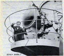
Figure 85-Typical bench mark location on searchlight platform.
with train figures given on bench mark data sheet, perform the installation tests listed in the following paragraphs.
Installation Tests
1. Telescope Pivot Training Test: This test is to check tightness or looseness of the telescope
pivot training gear train.
a. Crank the telescope pivot to the end of travel with the sight angle hand crank.
b. Set the target course dial at 270 degrees or 90 degrees.
c. Set target speed at any arbitrary value. (Suggest 30 knots.)
d. Release the sight angle hand crank-check the time to the end of travel. Maximum time should
be 30 seconds for a full swing.
2. Gyro Angle Transmission Test: Check the transmission of gyro angle between the director and
the torpedo course indicator by comparing the values on the indicator dials with values set in
director. Set in 90, 54, 2, 336, 310, and 284 degrees, in both increasing and decreasing
directions. Record the indicator dial readings. Calculate the total and average errors for both
increasing and decreasing readings. The maximum error should be less than 30 minutes of arc.
3. Torpedo Course Transmission Test (1- and 36-Speed): Check the transmission of torpedo
course. Set in 0, 59, 118, 177, 236, 295, and 354 degrees, both increasing and decreasing.
Record the indicator dial readings. Calculate the total and average errors for both increasing and
decreasing. The maximum error should be less than 30 minutes.
4. Own Ship Course Receiver Transmission Test-1 Speed: Check the transmission of own ship course values between the gyro compass and
the own ship course receiver unit. The maximum error should be less than 30 minutes.
5. Accuracy Test: By the relative bearing method of testing run the test problems 4 and 5,
figures 89 and 90, using the telescope and the bearing receiver. The computed answers as read
on the test indicators should not vary more than 30 minutes from the calculated answer. Own
ship course input to transmitter shall be manual.
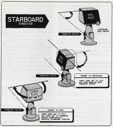
Instructions for Changing Directors to Accommodate Varying Mounting Positions (Port, Centerline, or Starboard):
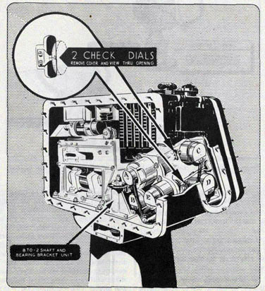
1. Remove the generator access hole cover on the left side of the case (looking toward dial face)
for viewing the check dials. See figure 86.
2. Set all dials to zero (outer main target bearing dial to 18 (180 degrees reading) by turning the
hand cranks. Further adjust the check dials to zero by means of the training handwheel and tube
offset crank. This positions the instrument to absolute zero.
3. The instrument is now trained for the zero setting made at the factory.
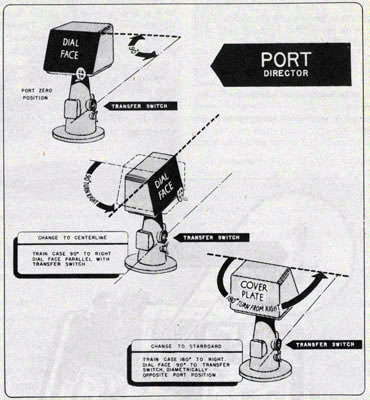
4. To convert a "Port" instrument to "Starboard" mounting, train the case 180 degrees to the right or
to convert a "Starboard" instrument to "Port" mounting, train the case 180 degrees to the left. For
conversion to a "Centerline" position, the case is trained 90 degrees. Use the check dials for accurate
setting and adjust to zero (check dials only). See figure 86.
5. Lock the training handwheel in position.
6. Remove the large cover plate 168033-1 and also the small cover plate on the apron
88
INSTALLATION-DIRECTOR
directly below to provide access to the BTO-2 shaft.
7. Remove the BTO-2 shaft and bearing bracket unit so that bevel gears disengage. Turn the
bevel gear on the BTO-3 by hand until face dials are returned to the zero setting.
8. Loosen the micrometer adjustment on BTO-2 shaft and mount the shaft and bearing bracket
unit in position. Readjust the check dials to zero with micrometer adjustment. Lock the adjustment.
9. To change a starboard director to port, see figure 88.
TORPEDO COURSE INDICATOR
The Torpedo Course Indicator Mk 1 Mods 0 to 4 is mounted on top of the Torpedo Course
Attachment Mk 1 and Mods. The following procedure is recommended for installing the torpedo
course indicator aboard ship.
1. Train the torpedo tube mount, so that the torpedo tubes are pointing directly forward, zero
degrees.
2. Turn the basic gyro setting hand crank until the gyro angle output of the torpedo course
attachment is zero degrees.
Figure 86-Diagram showing location of check dials and BTO-2 shaft in director.
89
TORPEDO FIRE CONTROL EQUIPMENT (DESTROYER TYPE) OP 1586
Figure 87-Diagram for changing a starboard director to a centerline or port location.
3. Remove the protecting guard from the bottom of the torpedo course indicator.
4. Turn the gyro angle input gear until the gyro angle dial indicates zero degrees gyro angle.
5. Turn the tube train input shaft until the tube train dial indicates zero degrees. The torpedo
course ring dials should also indicate a zero reading.
6. With the dials at zero, mount the torpedo course indicator on top of the torpedo course
attachment. Care should be taken in this step so that: (1) the dials are not disturbed, (2)
backlash in the mesh between the gyro angle input spur gear and the gear of the attachment is
reduced to a minimum, and (3) the tube train input shaft and key fit properly into the coupling
of the torpedo course attachment. If the dials of the indicator are disturbed, bring them back
to zero by using the adjustable couplings provided on the gyro angle vertical drive shaft and the
vertical training shaft of the torpedo course attachment.
90
INSTALLATION-INDICATOR
Figure 88-Diagram for changing a port director to a centerline or starboard director.
7. Secure the torpedo course indicator to the torpedo course attachment with six 5/8 in. bolts.
8. Remove the terminal board cover from the rear of the indicator case.
9. Pass the ship's electrical supply cable and the six-volt supply cable (for Mod 2 and 4
indicators only) through the terminal tubes into the instrument. Connect the electrical wires to
the terminal board as indicated on the Navy Lead Designation Table provided on the inside face of
the terminal board cover or by referring
to the following BuOrd wiring diagrams: (1) 160933 for Torpedo Course Indicator Mk 1 Mod 0,
(2) 180609 for Torpedo Course Indicator Mk 1 Mod 1, (3) 180685 for Torpedo course
Indicator Mk 1 Mod 2 (original design), (4) 230446 for Torpedo Course Indicator Mk 1 Mods
2 (later design) and 4, and (5) 238028 for Torpedo Course Indicator Mk 1 Mod 3.
10. Seal the electrical cables in the terminal tubes with packing designated on the wiring diagram.
91
TORPEDO FIRE CONTROL EQUIPMENT (DESTROYER TYPE) OP 1586
TELESCOPE MK 50 MOD 0
The Telescope Mk 50 Mod 0 is mounted on top of the telescope pivot of the torpedo director. The
following procedure is suggested for
attaching the telescope to the torpedo director:
1. Line up the telescope with the telescope pivot so that it fits in the groove of the telescope
mounting flange. Also make sure that the bolt holes in the mounting flange of the telescope
coincide with the tapped holes in the telescope pivot.
2. Fasten the telescope to the pivot with four bolts.
3. Connect the crossline illumination lamp of the telescope with the wiring leading from the pivot.
4. Sight the telescope on a target and check the illumination of the crosslines for all intensities.
FIRING KEY MK 19 MOD 0
The Firing Key Mk 19 Mod 0 is secured to a bracket on the left side of the Telescope Mk 50 Mods
0 and 1. The following procedure is suggested for attaching the firing key to the telescope bracket:
1. Loosen the clamping screw on the telescope bracket. See figure 27.
2. Insert the barrel end of the firing key in the bracket. Adjust the grip end of the key until it
remains in a vertical plane in relation to the telescope of the director.
3. Secure the firing key in this position by tightening the clamping screw of the telescope bracket.
4. Connect the firing key as designated on Bureau of Ships wiring diagram for the torpedo
director control system. Four leads are provided in the firing key, two for the torpedo firing
circuit and two for the ready light circuit.
92
Chapter 7
INSTALLATION CHECKS AND ADJUSTMENTS
This chapter deals with the initial checks and adjustments necessary to put the torpedo director,
telescope, firing key and torpedo course indicator in good operating condition.
TORPEDO DIRECTOR
Mechanical Checks
1. Remove the gyro angle hand crank cover and set the check dials to zero. Set all the dials of the
torpedo director to "0" by turning the various hand cranks. The target course dial will now read
"180". The selector switch, at the director stand, must be positioned to "OFF".
2. Rotate the training handwheel of the director until the ring dials of the bearing receiver or
the middle dial of the main dial group "A" indicate the bearing of the bench mark. See figure
85.
3. Look through the director telescope and sight on the bench mark. If the telescope crossline is
off the bench mark, the following adjustments must be performed to bring the telescope on:
a. Loosen the clamping screws of the micrometer adjustment on shaft Dsk 8. These screws are
accessible through the fuse block opening.
b. Turn the micrometer adjustment until the telescope crossline is brought to bear on the bench
mark. Check to see that the sight angle dials remain at "0".
c. With the telescope correctly set, lock the micrometer adjustment by tightening the clamping
screws.
4. Turn the training handwheel and train the director to zero degrees relative target bearing.
At this bearing, the ring dials of the bearing receiver read "0" and the middle dial of the main
dial group "A" should indicate "180".
5. Check to see that the sight angle scale at the telescope agrees 'With that of the corrected sight
angle dial. Both should indicate zero
785193-47-7
degrees. If the scale at the telescope does not read "0", adjust scale pointer until it is opposite the
zero mark on the scale. The pointer can be adjusted by loosening clamping screws and shifting the pointer as required.
6. Turn selector switch on the director stand to the "OSC OFF" position. If all adjustments have
been made correctly the telescope will not move. With the switch on this position, own ship
course can be received by the one-speed synchro motor with the follow-up servo motor cut out.
7. Turn the training handwheel and check to see that the director trains easily.
8. Turn the elevating knob of the telescope and check to see that the line of sight of the telescope
elevates and depresses correctly.
9. Check all the glass dial windows to see that none of them are broken or cracked.
Electrical Checks
The electrical checks consist of testing the synchro transmission system, power supply, dial
illumination, and firing circuit.
Relative Target Bearing.-The relative target bearing transmission system can be checked by performing the following:
1. Set all dials of the director to "0" by turning the various hand cranks, except the target
course dial which should read "180". Also, turn the selector switch to the "OFF" position.
2. Send a definite relative target bearing signal, say 38 degrees to the bearing receiver. The signal will
position the inner dials of the 1- and 36-speed dial groups.
3. Turn the training handwheel and train the director until the ring dials match the inner dials.
4. Check the reading of the ring dials to see that they agree with the signal being received, 38 degrees.
If the dials don't agree, the synchro motors that operate the inner dials have to be set on
93
TORPEDO FIRE CONTROL EQUIPMENT (DESTROYER TYPE) OP 1586
electrical zero and the inner dials set to correspond with the zero setting. To adjust these inner
dials, the following must be done:
a. Remove the front cover from the bearing receiver.
b. Using the procedure outlined in OP 1303, "United States Navy Synchros", put synchro motors on electrical zero.
c. Loosen the dial clamping screws and slip the inner dials, so that their indexes line up with the
fixed indexes on the dial face plate.
d. Replace front cover of instrument.
5. Check accuracy of adjustment to the inner dials by: (1) sending another signal to the
instrument, (2) turning the training handwheel until the dials are matched, and (3) comparing
the reading obtained from the ring dials to see that it agrees with the transmitted signal. If the
reading is still incorrect, further adjustment to the inner dials is necessary.
Own Ship Course.-This test will consist of two parts. The first part deals with the synchro
transmission system and the second part, the operation of the own ship course follow-up mechanism.
1. Turn the selector switch mounted on the director stand to "OSC OFF". This will allow the one-speed synchro motor to receive own ship course, but will cut out the servo motor and the follow-up mechanism.
2. Put the own ship course crank in the "IN" position.
3. Send an own ship course signal to the torpedo director. This will displace the own ship
course zero reader dial.
4. Turn the own ship course hand crank until the own ship course zero reader dial is restored to "0".
5. Check the reading of the one-speed own ship course dial to see that it agrees with the
transmitted signal. If the reading does not agree, the own ship course synchro motor must be
adjusted for electrical zero. This adjustment can be performed as follows:
a. Remove the own ship course dial window from the director case.
b. Using the procedure outlined in OP 1303, put the synchro motor on electrical zero.
c. Loosen the two dial clamping screws and slip the dial until its index is lined up with the fixed
index on the dial face plate.
d. Lock the dial in this position by tightening the clamping screws.
6. Check accuracy of adjustment by: (1) sending another signal to the director, (2) turning the
hand crank to restore the zero reader dial, and (3) comparing the reading obtained from the
own ship course dial to see that it agrees with the transmitted signal. If the reading is still
incorrect, further adjustment to the zero reader dial is necessary. Replace the dial window.
7. To check the operation of the own ship course follow-up mechanism the following steps must
be taken:
a. Put the own ship course hand crank in the "OUT" position. With the crank in this position, the
switch in the supply circuit for the servo follow-up motor is closed.
b. Turn the selector switch, mounted on the director stand to the "ON" position.
c. Send an own ship course signal to the torpedo director.
d. When all motion ceases, that is the own ship course zero reader dial is restored to "0", check
the reading of the own ship course dial to see that it agrees with the transmitted signal. If
relative target bearing set into the director is "0", the outer ring dials of the main dial groups
"A" and "B" should also indicate the same value of own ship course as the transmitted signal. If
the reading of the own ship course dial does not agree with the transmitted signal, the follow-up
mechanism must be adjusted.
Gyro Angle.-The gyro angle transmission system can be checked as follows:
1. Turn the gyro angle crank until the gyro angle dials indicate some value, say 45 degrees.
2. At the torpedo tube mount, have the basic gyro setting crank turned until the gyro angle dials
of the torpedo course indicator are matched.
3. Compare the reading of the gyro angle dial at the torpedo course indicator with the value set
into the torpedo director. If the dial
94
INSTALLATION CHECKS AND ADJUSTMENTS-DIRECTOR
reading of the torpedo course indicator does not agree, there are three possible causes: (1) the
gyro angle synchro generator in the torpedo director may be off electrical zero, (2) the gyro
angle dials of the torpedo director may be set incorrectly, that is, the dial is out of synchronism
with the synchro generator, or (3) the gyro angle synchro motor in the torpedo course
indicator may be off electrical zero. The following procedure is recommended to adjust or
correct for these three conditions:
a. Turn the gyro angle crank until the gyro angle dials indicate "0".
b. At the torpedo director, check the synchro generator for electrical zero as described in OP
1303. If the synchro generator is off electrical zero, set it on electrical zero by loosening the
generator clamping screws and turning the stator of the generator until electrical zero is indicated.
c. At the torpedo course indicator,, check the gyro angle synchro motor for electrical zero as
described in OP 1303. With the synchro motor set on electrical zero, adjust the dial, connected
to the rotor of this motor, so that its index is lined up with the fixed index on the dial face plate.
This can be done by loosening the dial clamping screws and slipping the dial until its index is
lined up correctly. Lock the dial in this position by tightening the clamping screws, using
special tool 8-Z-940-1 which will be found in the spare parts box.
Torpedo Course. The torpedo course transmission system can be checked as follows:
1. Set all the dials of the torpedo director to zero by turning the various cranks. Make sure the
tube-offset dial is set at zero.
2. Turn the training handwheel until the torpedo course dials indicate some angle, say 32 degrees.
3. At the torpedo mounts, have the training hand crank turned until the one- and 36-speed
torpedo course dials of the torpedo course indicator are matched. If the dial readings of the
torpedo course indicator do not agree, there are three possible causes:
a. The one-and 36-speed torpedo course synchro generators in the torpedo director may be off
electrical zero.
b. The torpedo course dials of the torpedo director may be set incorrectly, that is, the dial is out
of synchronism with the synchro generators.
c. The one- and 36-speed torpedo course synchro generators in the indicator may be off electrical zero.
The following procedure is recommended to adjust or correct for these three conditions:
1. Turn the training handwheel until the torpedo course dials and the check dial indicate
2. At the torpedo director, check the one- and 36-speed torpedo course synchro generators for
electrical zero as described in OP 1303. If the synchro generators are off electrical zero, set
them on electrical zero by loosening the clamping screws of the generators and turning the
generator stators until electrical zero is obtained.
3. At the torpedo course indicators, check the one- and 36-speed torpedo course synchro motors
for electrical zero as described in OP 1303. With the synchro motors set on electrical zero,
adjust the dials connected to the rotors of the motors so that their index is lined up with the
fixed index on the dial face plate. This can be done by loosening the dial clamping nut and
slipping the dials until their index is lined up correctly. Use special tool 8-Z-940-1. Lock the
dials in this position by tightening the clamping screws.
Dial Illumination. The dial illumination system can be checked by performing the following tests:
1. Turn on the lighting supply circuit to the torpedo director.
2. Open each lightwell and check to see that both lamps in each lightwell are on.
3. Turn the knob of the crossline rheostat in the direction for increasing illumination and see
that the telescope crosslines are illuminated properly, that is, the illumination should become
brighter as the knob is turned to "BRIGHT".
4. Check to see that the illumination transfer switch is operating properly. This is done by
throwing the switch from "TRANSFORMER"
95
TORPEDO FIRE CONTROL EQUIPMENT (DESTROYER TYPE) OP 1586
to "BATTERY" and checking the lightwells to see that the lamps remain on.
5. In addition to the above, turn the selector switch to "ON" and check to see that the heater is
operating. The heater should throw off heat when the circuit is turned on. To check this heater,
the rear cover plate must be removed from the torpedo director. Open the fuse box and check to
see that none of the fuses are burned out. Replace any burned out fuses.
6. Also check all wires to see that none of them are grounded or cut.
Firing Circuit. The operation of the firing key is checked by closing the key and checking to see
that it completes the firing circuit.
CAUTION: Be sure that the torpedo tube does not fire unless it is intended to fire.
Final Checks
Before the torpedo director is put into actual operation, several torpedo control problems
should be set up on the director and the results checked against calculated data for these
problems. Two different torpedo control problems are given in figures 89 and 90. If the given
quantities are set up correctly in the director and if the director is operating properly, the
values for torpedo course, basic sight angle and corrected sight angle as produced by the
director should agree with the values given for these quantities in the problem. For example:
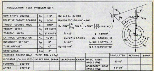
Using the values given in Problem No. 4, set the following quantities into the torpedo director:
(1) 110 degrees own ship course, (2) 200 degrees relative target bearing, (3) 70 degrees target course, (4) 25 knots target speed, (5) 27 knots torpedo speed, (6) 40' (north) latitude correction, and (7)
zero degrees for intercept offset, tube offset and gyro angle. As shown in figure 89 for this set-up, the torpedo course dials should indicate 252 degrees 39', the basic sight angle dial 53 degrees 19', and
the corrected sight angle dial 52 degrees 39'.
If the torpedo director produces results that are more than 30 minutes off the calculated
results, the internal mechanism should be checked and adjusted. These checks and adjustments
should be performed by a maintenance man who knows the equipment and how to correct the
trouble. If during any of these tests, troubles are found, refer to the Maintenance Section for
possible remedies.
Figure 89-Test problem No. 4.
96
INSTALLATION-CHECKS AND ADJUSTMENTS-INDICATOR
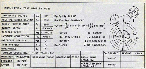
Figure 90-Test problem No. 5.
TORPEDO COURSE INDICATOR
Mechanical Checks
1. Check all the glass windows to see that none of them are broken or cracked.
2. Check all the dials to see that none of them are warped or cracked.
3. Train the torpedo tube mount to see that the tube train dial and the one- and 36-speed
torpedo course ring dial operates or rotates.
4. Turn the gyro angle setting crank, see that the gyro angle ring dial responds.
Electrical Checks
The electrical checks for the indicator consist of testing the operation of the synchro motors
(transmission system) and dial illuminations.
Torpedo Course. Send a torpedo course signal from the director to the indicator. See that the
inner dials of the one- and 36-speed torpedo course dials respond to the signal, both as to
direction of rotation and amount of the rec1il signal.
The amount of the signal can be checked by training the torpedo tube mount until the dials
are matched and then comparing the reading
obtained from the ring dials with the transmitted signal.
Note: If during this test, the dials are found not to be operating properly, they can be adjusted
using the procedure outline on page 93.
Gyro Angle. Send a gyro angle signal from the director to the indicator. See that the inner dial of
the gyro angle dials responds to indicate the amount of the signal.
The amount of the signal can be checked by turning the gyro angle setting crank until the dials
are matched and then comparing the reading obtained from the ring dial with the transmitted signal.
Note: If during this test, the dials are found not to be operating properly, they can be adjusted
using procedure outlined on page 94.
Dial Illumination. The dial illumination system can be checked by performing the following tests:
1. Turn on the lighting supply circuit to the indicator.
2. Open each lightwell and check to see that both lamps are on.
97
Chapter 8
MAINTENANCE
This chapter deals with the normal maintenance required to keep the Torpedo Director Mk 27
Mods 1 to 9 and the Torpedo Course Indicator Mk 1 Mods 0 to 4 in good operating condition.
TORPEDO DIRECTOR
The torpedo director is a precision instrument and as such requires the care accorded to other
similar fire control instruments.
The gears forming a part of the interior mechanism are cut with extreme accuracy and the
presence of dirt, grit, and other foreign matter within the case may seriously affect, if not
destroy, the effectiveness of the director. The various covers should be kept properly secured at
all times, except when repairs or inspections are being made.
Cleaning
Cotton waste or other materials likely to leave threads or lint within the case should never
under any circumstances be used. Cheese cloth or muslin is far more satisfactory and will
eliminate a source of possible serious trouble.
Operating Hand Cranks
Undue force must never be placed upon any handwheel or crank. If an abnormal condition should
exist, operation of the director should be stopped immediately and the cause ascertained and
removed. Failure to heed this caution may result in serious casualties to the interior
mechanism such as stripped gears or sheared pins.
Friction Adjustments
All hand cranks, except those used for training the director and the knob used for introducing
latitude correction, are provided with adjustable friction devices so designed that slip
will occur if the interior mechanism is subjected to undue stress. The friction should be enough
to operate the mechanism and no more. In no case should the moment applied exceed (30) thirty
inch/pounds in order to produce slipping.
The director is constructed almost exclusively of corrosion resisting materials, virtually
eliminating troubles from corrosion. However, due to inevitable breathing of the case and stand
some moisture may find its way in and result in slight corrosion of some of the parts.
Periodic Checks and Lubrication
The following check-off list gives the periodic cheeks and lubrication required which will help
insure satisfactory operation of the torpedo director, telescope, and firing key.
The frequency with which these checks are made depends upon the type of service and ship board doctrine. A suggested frequency for the checks is given below.
If, when checking the instruments, any troubles are found, refer to the trouble-shooting chart,
page 100, for probable causes and remedies to be used in correcting these troubles.
A. Daily
1. Energize all torpedo control circuits.
2. Check communications with tube mounts, synchro transmission of torpedo course order and
gyro angle order, ready-lights, and buzzers.
3. Insure that director heater is kept energized in cold weather.
4. Clean telescope and front window with lens paper. Also, clean glass windows of director if necessary.
5. Check firing circuits. This may be done by opening the torpedo tube breech door and
connecting a test lamp between the firing pin and ground.
98
MAINTENANCE-INDICATOR
B. Weekly
1. Replenish torpedo director grease fittings (seven) with bearing grease, specification 14 G 10 (Ord).
2. Check ship's 6-volt battery supply.
3. Train director on bench mark and check to see that target bearing dials indicate the bench
mark bearing.
C. Monthly
1. Remove the two covers on the lower part of the director case. Clean exposed gearing with a
bristle fibre brush and coat lightly with bearing grease, specification 14 G 10 (Ord).
2. Lubricate all hand cranks by placing several drops of light preservative oil (NAVORD OS 1362) between knob hand crank shaft housing to prevent freezing.
3. Check dial illumination and crossline illumination. Where both battery and ship line supply
are provided, check both.
Figure 91-Measuring clearance between points of follow-up switch.
Figure 92-Checking clearance on motor damper.
4. Fill zerk fittings (2) on telescope pivot with bearing grease, specification 14 G 10 (Ord).
5. Check alignment of torpedo director. For procedure involved in performing this check, see
page 86.
D. Quarterly
1. Check firing circuits electrically by firing each barrel from each director station using test lamp.
E. Annually
1. Remove all covers of torpedo director and inspect interior mechanism.
2. Check all electrical connections for cleanliness and tightness, covering any which become corroded frequently with a thick coat of light
grease.
3. Check all contacts on follow-up mechanism, limit switch, and hand crank switches for
fitting; clean and adjust as necessary.
4. Insofar as parts of torpedo director are accessible without disassembling any of the
mechanism, clean with brush or lint-free cloth and lubricate as follows:
99
TORPEDO FIRE CONTROL EQUIPMENT (DESTROYER TYPE) OP 586
a. Lubricate all stops with vaseline (Navy Spec. 14-P-1); run traveling nut down worm or
operate worm against wheel for full length; wipe off excess vaseline.
b. Brush light mineral oil on all spur and bevel gears.
c. Apply one drop of Nujol or ice-machine oil (NAVORD 05 1362) to all ball bearings.
d. Lubricate all slides and similar mechanisms with vaseline (Navy Spec. 14-P-i) and wipe off excess.
TORPEDO COURSE INDICATOR
Periodic Checks and Lubrication
The following check-off list gives the periodic checks and lubrication required which will help
insure satisfactory operation of the torpedo course indicator.
If, when checking the instruments, any troubles are found, refer to the Trouble Shooting Chart,
page 104, for probable causes and remedies to be used in correcting these troubles.
A. Daily
1. Energize the circuits to the instrument. Check to see that the dials are illuminated
properly.
2. Send a torpedo course signal to the indicator and see that the inner dials of the torpedo
course
dials respond to the signal. Train the torpedo tube mount and see that ring dials respond to
match the signal.
3. Send a gyro angle signal from the director to the indicator and see that the gyro angle inner
dial responds. Turn the gyro angle setting crank at the tube mount and see that the ring dial
responds to match the signal. This test does not apply to the Mod 3 indicator, since this
instrument does not have a gyro angle synchro motor.
4. Clean the glass windows of the instrument, if necessary.
B. Monthly
1. Check to see that none of the dials is cracked or warped.
2. Examine the glass windows to see that none of them is cracked or broken.
3. Check to see that all covers are tight.
C. Annually
1. Remove both covers of the torpedo course indicator and inspect the internal mechanism.
Caution. Great care should he exercised in removing the front cover from the indicator to avoid
damaging dials with projections on the cover. Thus, before removing the front cover from the
indicator, first remove hack cover and then disconnect lightwell leads at the terminal boards.
2. Check all electrical connections for cleanliness and tightness, covering any which become
corroded with a thin coat of bearing grease, Specification 14 G 10 (Ord).
3. Insofar as parts of the torpedo course indicator are accessible without disassembling any of
the mechanism, clean with brush or lintfree cloth and lubricate as follows:
a. Lubricate all worms with worm gear lubricant (NAVORD OS 1400) ; wipe off excess.
b. Brush with light mineral oil (Navy Symbol 3050 or 2135) all spur gears and bevel gears.
c. Apply one drop of light preservative oil (NAVORD OS 1362) to all ball bearings.
CARE AND MAINTENANCE OF TELESCOPE
See chapter 8 of OP 582 (First Revision) for information and instructions regarding the care
and maintenance of telescopes.
100
MAINTENANCE DIRECTOR
Trouble Shooting Chart
Torpedo Director Mk 27 Mods 7 to 9
Trouble
Probable Cause
Remedy
Oscillation of computer (does not stop operating)
Binding of follow-up gear train at rear of computer
Indicate all shafts to see that they are running true. Straighten bent shafts. Check to see if bearings bind. Set shafting brackets for better fit.
Sticky reader dials
Check to see that there is three thousandths clearance between reader dials and dial shields. If dial is eccentric straighten dial shaft.
Sticky or dirty follow-up switch points
Wash follow-up switch assembly in cleaning fluid. Sand and set switch points with a minimum clearance of 0.006 inches and a maximum clearance of 0.008 inches.
NOTE: If above remedies do not stop oscillation try the following:
a. Adjust follow-up switch damper screw upward within 0.001 inches of switch arm. Make certain the center contact barely touches left contact. This is the extreme upward screw position recommended. See figure 91.
b. Adjust the sight angle motor brake to a minimum of 0.006 inches, when power is off. See figure 92.
Worm and worm wheel on telescope pivot freezing or binding.
Disassemble and overhaul telescope pivot. Set gear and worm so worm can be turned by hand.
Rusty bearings caused by salt water or spray penetrating case while open at sea.
Remove own ship course, computer and transmitter units from case and overhaul at shore base-or install new director.
Too little clearance between points on follow-up switch.
Flatten and set switch points with a minimum clearance of 0.006 inches and a maximum clearance of 0.008 inches.
High problem errors
Improper zeroing of machine.
Zero machine correctly as outlined on page 102.
Backlash of input hand cranks.
Adjust gears to take up backlash between hand crank handle and mating gear.
Too much clearance between points on follow-up switch.
Flatten and set switch points with a minimum clearance of 0.006 inches and a maximum clearance of 0.008 inches.
Backlash in dials and mating gears.
Reduce the clearance between mating and dial gears, to a minimum. See that they do not bind.
Loose shaft taper pins
Use larger pins or re-ream holes.
101
TORPEDO FIRE CONTROL EQUIPMENT (DESTROYER TYPE) OP 1586
Trouble
Probable Cause
Remedy
Backlash or endplay in training hand crank shaft.
Place shim between hand crank and bushing.
BTO-2 Backpost assembly backlash due to worn parts or worn gear key.
Check to see if key is tight, also that the gear does not turn on shaft. Set backpost closer to mating gear in order to remove backlash.
Sticky dials on own ship course unit.
Re-adjust dial shield to 0.003 inches clearance between dial and shield.
Heart-shaped cam zero out of phase with electrical zero.
Check synchro motor with standard synchro and adjust cam on shaft to proper zero by loosening friction clamp on heart-shaped cam.
Improper spacing of points on own ship course unit follow-up switch.
Flatten and set switch points with a minimum clearance of 0.004 inches and a maximum clearance of 0.008 inches.
Broken pig tail on own ship course unit follow-up switch
Replace and make sure new pig tail does not interfere with moving parts on director.
Director sluggish
Telescope train motor brake dragging.
Open brake to 0.012 inches maximum to allow more clearance.
Worm and worm wheel on telescope pivot freezing or binding.
Disassemble and overhaul pivot assembly.
Salt water in director case
Remove own ship course, computer and the transmitter assemblies from case and overhaul director at shore base or install new director.
Large error in transmission of signals between director and torpedo course indicator.
Improper zeroing of synchro motors.
Hook up synchro motor to standard synchro generator on test stand.
Sticky bearings in synchro motors in indicator.
Remove synchro motors. Replace with new ones.
Improper hook-up of director electrical connections to ship's wiring.
Check to see if proper connections have been made.
Short circuits.
Check continuity of electrical circuits also check short circuits to ground with megger-if reading is less than 5 megohms remove lamps from lightwells and recheck. Continue search for shorts.
102
MAINTENANCE-DIRECTOR
PROBABLE OPERATION DIFFICULTIES TORPEDO CONTROL SYSTEM
Trouble
Recognition
Remedy
Failure of 115-volt a-c supply.
Director fails to generate change in sight angles (telescope motion) when inputs are changed. Tubes fail to follow director.
Engage sight angle hand crank and keep zero reader dials matched. Transmit torpedo course angle and gyro angle to tubes by phone. Crank in own ship course to use true values.
Failure to receive own ship course from master gyro
Ship swings and own ship course dial does not follow.
Engage own ship course hand crank and set in own ship course by hand.
Failure of own ship course follow-up unit.
Ship swings and own ship course dial does not follow.
Engage own ship course hand crank and keep own ship course zero reader matched by hand.
Failure of sight angle motor to follow up.
Director fails to generate change in sight angle (telescope motion) when inputs are changed.
Engage sight angle hand crank and keep zero reader dials zeroed.
Failure of gyro angle order transmission.
Tubes report "Danger Bearing" and director gyro angle is not in danger bearing.
Transmit gyro angle orders by phone.
Failure of torpedo course order transmission.
Tube mount reports: "matched pointers do not check with tube mount sight."
Shift to bridge control or local aim for short range and good visibility. Transmit torpedo course order by phone for long range and poor visibility.
Damage to telescope. Remainder of director operative and target visible.
Optical and physical damage to telescope.
Get bearing from radar. Shift to bridge control or local aim and transmit sight angle to tubes by phone. Use director to compute sight angle. Keep director trained to best available target bearing.
Director completely out of commission.
Director fails to generate either electrically or manually.
Shift to bridge control or local aim; transmit data for tube sight by phone.
Failure of ready lights.
Lack of indication of annunciators.
Use phones to report "Ready", etc.
Failure of firing.
Misfire when director firing key is closed.
Fire by percussion on orders from Control.
Tube jams outside danger bearing.
Reported from tubes.
Order tubes to match torpedo course pointers by setting gyro angle as required. For torpedoes in which gyro spindles cannot be engaged; tubes report tube train angle on which jammed; director sets up problem to correspond; swing ship to bring cross-lines on and fire.
Note: Shift to local control as a last resort when all communication with tube mount is lost.
103
TORPEDO FIRE CONTROL EQUIPMENT (DESTROYER TYPE) OP 1586
Trouble Shooting Chart for Torpedo Course Indicator Mk I Mods 0 to 4
Troubles
Causes
Remedies
No dial illumination
Burned out lamps in lightwells
Inspect lamps and replace burned-out lamps
Loose wire connections from terminal boards to lightwells
Check wire connections and tighten as necessary
Torpedo course inner dials not operating properly
Loose wire connections to torpedo course synchro motors
Check wire connections and tighten as necessary
Synchro motors in indicator not set on electrical zero
Put synchro motors on electrical zero a described in OP 1303 "US Navy Synchros"
Burned out synchro motors
Remove burned-out motor and replace with new one
Dial stuck, not enough clearance between ring dial and inner dial
Remove inner dial and scrape under ring dial to make clearance
Dials cracked or warped
Remove damaged dial and replace with new one
Gyro angle inner dial not operating properly
Loose wire connections to gyro angle synchro motor
Check wire connections and tighten as necessary
Synchro motor not set on electrical zero
Put synchro motor on electrical zero as described in OP 1303
Burned out gyro angle motor
Replace with new one
Dial stuck, not enough clearance between ring dial and inner dial
Remove inner dial and scrape under rim of dial to make clearance
Dial cracked or warped
Remove damaged dial and replace with new one
Ring dials or tube train dial not operating
Cracked dial Replace damaged dial with new one
Stripped gears in indicator
Open cover, inspect internal mechanism. Replace any damaged gears.
Glass windows fogged
Covers not bolted to give water-tight seal
Tighten down all covers.
Moisture in indicator
Dry out instrument-check for rust. Make necessary repairs. Tighten down all covers.
Glass windows cracked
Uneven pressure on window retainer
Replace damaged glass and gasket with new one. Tighten down retainer evenly.
Retainer bolted down too tightly
Replace glass and gasket and tighten retainer just enough to make water-tight seal between glass and cover.