TORPEDO FIRE CONTROL EQUIPMENT (DESTROYER TYPE), OP 1586, 27 February 1947 was created just after WW II. It describes the peak of WW II US destroyer torpedo fire control technology.
In this online version of the manual we have attempted to keep the flavor of the original layout while taking advantage of the Web's universal accessibility. Different browsers and fonts will cause the text to move, but the text will remain roughly where it is in the original manual. In addition to errors we have attempted to preserve from the original this text was captured by optical character recognition. This process creates errors that are compounded while encoding for the Web.
Please report any typos, or particularly annoying layout issues with the Mail Feedback Form for correction.
TORPEDO DIRECTOR MARK 27 TELESCOPE MARK 50 FIRING KEY MARK 19 TORPEDO COURSE INDICATOR MARK 1
27 FEBRUARY 1947
This publication is RESTRICTED and shall be safeguarded in accordance with the security provisions of U. S. Navy Regulations 1920, Article 76.
NAVY DEPARTMENT BUREAU OF ORDNANCE WASHINGTON 25, D. C.
27 February 1947
RESTRICTED
ORDNANCE PAMPHLET 1586
TORPEDO DIRECTOR MARK 27 MODS 1 TO 9
WITH TELESCOPE MARK 50 MODS 0 AND 1,
FIRING KEY MARK 19 MODS 0 AND 1,
AND THE TORPEDO INDICATOR MARK 1 MODS 0 TO 4
1. This Ordnance Pamphlet contains information on the description, operation, installation,
maintenance, and overhaul of destroyer type fire control equipment. The equipment includes the
Torpedo Director Mark 27 Mods 1 to 9 with Telescope Mark 50 Mods 0 and 1 and Firing Key
Mark 19 Mods 0 and 1 installed and the Torpedo Indicator Mark 1 Mods 0 to 4.
2. The description of the torpedo director includes the alterations which were authorized by the
following NAVORD ORDALTS:
ORDALT 1255-Instructions for installing centering device for sight angle motor follow-up
ORDALT 1787-Installation of red illumination for dials
ORDALT 2107-Installation of relative target bearing receiver
3. This publication supersedes Ordnance Pamphlet 585 (Second Revision), which should be destroyed
4. Ordnance Pamphlet 1586 is RESTRICTED and shall be safeguarded
ordnance with the security provisions of U. S. Navy Regulations, 1920,
Article 76.
G. F. HUSSEY, JR. Vice Admiral, U. S. Navy Chief of Bureau of Ordnance
TORPEDO FIRE CONTROL EQUIPMENT (DESTROYER TYPE) OP 1586
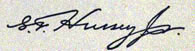
Figure 1-Torpedo Director Mk 27 Mods 1 to 9 is a torpedo fire control instrument. This view
shows the director installed on the bridge of a modern destroyer.
iv
Chapter I
TERMINOLOGY
This section defines the basic torpedo fire control terms used in this manual. A thorough
understanding of these terms at the start will help clarify the principles and operation of the
torpedo director. Firing Point: This is the point where the torpedo begins its run; broadly, the position of own
ship when the torpedo is fired. Line of Sight: The straight line from the axis of rotation of the torpedo director to the point of
aim on the target. Point of Aim: The desired point on the target to be hit with the torpedo.
Torpedo Track: The path along which the torpedo proceeds through the water.
Usually, when a torpedo is fired, it travels in a straight line for a certain distance called the
reach. At the end of this period of straight line travel, it may be caused to start on a circular
course. The arc of the circular path is determined by setting the gyro in the torpedo. At the end
of the circular path, the torpedo proceeds to the target in a straight line. This final straight line
of the torpedo is called final track of the torpedo.
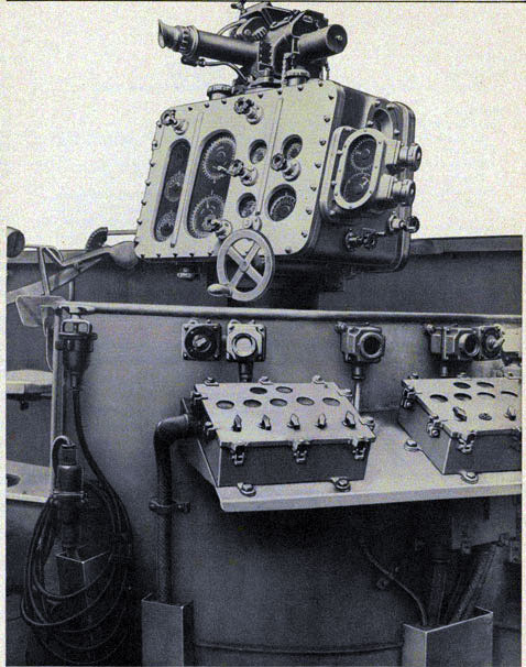
The various torpedo fire control symbols and
terms, defined below, are illustrated in figure 2.
Symbol
Definition
B
True Target Bearing: The angle between the north-south line and the line of sight to the target, measured clockwise from the north (measured from 0 degrees to 360 degrees).
Bgy
Gyro Angle: The angle between the axis of the torpedo tube and the final track of the actual torpedo, measured clockwise from the torpedo tube (measured from 0 degrees to 360 degrees). Gyro Angle Order is the value of gyro angle which is ordered to be set into the torpedo. In the torpedo fire control system described in this manual, gyro angle order is transmitted electrically at two-speed from the torpedo director to the torpedo course indicators at the torpedo tube mounts.
Bt
Target Angle: The angle between the fore and after axis of the target and the line of sight to the target, measured clockwise from the target's bow (measured from 0 degrees to 360 degrees).
Bs
Relative Target Bearing: The angle between the fore and after axis of own ship and the line of sight to the target, measured clockwise from the own ship's bow (measured from 0 degrees to 360 degrees).
Bto
Torpedo Course: In this manual reference is made to torpedo course. This term should be called Relative Torpedo Course because it is torpedo course angle measured relative to own ship.
TorpedoCourse (relative) is the angle between fore and after axis of own ship and the final track of the actual torpedo, measured clockwise from the ship's bow (measured froth 0 degrees to 360 degrees).
Torpedo Course Order is the value of torpedo course computed by the director.
Btr
Track Angle: The angle between the final track of the torpedo and the fore and after axis of the target measured clockwise from the bow of the target.
Btu
Basic Tube Train: The computed angle between the fore and after axis of own ship and the axis of the torpedo tube mount measured clockwise from the ship's bow (measured from 0 degrees to 360 degrees). Basic tube train does not include tube offset.
B'tu
Actual Tube Train: The angle between the fore and after axis of own ship and the axis of the torpedo tube mount, corrected for tube offset, measured clockwise from the ship's bow (measured from 0 degrees to 360 degrees). In this manual, actual tube train does include tube offset and is equal to the algebraic sum of torpedo course (corrected for tube offset) and gyro angle. Figure 2 illustrates the case where actual tube train is equal to torpedo course minus gyro angle.
1
TORPEDO FIRE CONTROL EQUIPMENT (DESTROYER TYPE) - OP 1586
Figure 2-Graphic explanation of terminology.
2
TERMINOLOGY
Thus, actual tube train is the angle that the torpedo tubes make with the fore and After axis of own ship when torpedo course and gyro angle dials of the torpedo course indicator are matched. For a complete description of how actual tube train is produced, see page 11.
Co
Own Ship Course: The angle between the north-south line and the fore and after axis of own ship, measured clockwise from the north to the bow of own ship (measured from 0 degrees to 360 degrees).
Ct
Target Course: The angle between the north-south line and the fore and after axis of the target, measured clockwise from north to the bow of the target (measured from 0 degrees to 360 degrees).
Ds
Basic Sight Angle: The computed angle from the line of sight to the final track of the torpedo measured clockwise.
Dsk
Corrected Sight Angle: This is basic sight angle with latitude correction and intercept offset correction applied.
H
Target Run: Distance run by target during the time of torpedo run.
Kla
Latitude Correction: The correction required to compensate for the error due to proving (balancing) a torpedo gyro in one latitude and firing it in another. In other words, this correction is a change in sight angle to compensate for the inherent tendency of the torpedo to creep to the right in northern latitudes and to the left in southern latitudes, due to the earth's rotation. This quantity depends upon latitude and duration of the torpedo run.
Osi
Intercept Offset: This is an arbitrary change in sight angle, right or left, to produce an offset angle, thus changing the point of intercept.
Otu
Tube Offset: The angle between the tube mount axis and the basic tube train measured right or left from the basic tube train.
In other words, tube offset is the angle by which torpedo course orders, transmitted from the director to the two torpedo tube mounts, are diverged
symmetrically about the basic (computed) torpedo course to obtain a spread between the mounts. In the torpedo director, tube offset is the angle between basic torpedo course and actual torpedo course.
Q
Spread Angle: The angular difference between the final track of two adjacent torpedoes fired from the same tube mount exclusive of any change in basic gyro angle of the torpedoes.
So
Own Ship Speed: Speed of own ship in knots.
St
Target Speed: Speed of target in knots.
Sto
Torpedo Speed: The average speed, in knots, of the actual torpedo from the muzzle of the tube to the point of intercept.
Xt
Target Deflection: This is the component of target speed, perpendicular to the line of sight. In the torpedo director, this term is computed according to the equation,
Xt = St Sin Bt. Target deflection equals target speed times the sine of target angle.
Xto
Torpedo Deflection: This is the component of torpedo speed, perpendicular to the line of sight. In the torpedo director, this term is computed according to the equation,
Xto = Sto Sin Ds. Torpedo deflection equals torpedo speed times the sine of basic sight angle.
Speed Ratio: The term speed, such as one-speed
or 36-speed, is used to indicate the ratio between a dial or shaft and the basic quantity with
which it is associated. It has no relation to the sense of velocity. A clock, for example, measures
the rotation of the earth. The small hand makes two revolutions per day, and thus operates at
two-speed, while the big hand makes 24 revolutions to one revolution of the earth, operating at 24-speed.
Thus, if a torpedo course dial or shaft turns at one-speed, it makes one complete revolution for
each 360 degrees of torpedo course. If the dial or shaft operates at 36-speed, it makes 36 revolutions
for each revolution of the one-speed dial or 360 degrees. Therefore, one revolution of the 36-speed,
dial or shaft represents 10 degrees.
3
TORPEDO FIRE CONTROL EQUIPMENT (DESTROYER TYPE) OP 1586
In this manual the term speed will also be used in relation to the sense of velocity. Thus, in the
term target speed or torpedo speed, speed means the velocity of the target or the torpedo and is
usually expressed in knots.
COMPUTING LATITUDE CORRECTION
Latitude correction, Kla, is calculated and introduced, as a hand input, in the Torpedo Director
Mk 27 Mods 1 to 9.
Several U. S. Navy publications develop the theory which underlies gyroscopic creep and
latitude correction. One particular publication is OP 627 (A), "U. S. Navy Torpedo Gyroscopes,
Non-Tumble Type". For the present purpose, it is sufficient to state that when the latitude in
which torpedoes are fired differs from that for which the gyro balance nuts are set, a latitude
correction to sight angle should be applied.
Either formula (1) or formula (2) given below should be used, as appropriate, to calculate the
latitude correction
Kla = (0.0037 X R X (Sin L2-Sin L1)) / Sto (1)
or
Kla = (0.0037 X R X (Sin L2+Sin L1)) / Sto (2)
where Kla = latitude correction in degrees
R = =torpedo run in yards
L2 = firing latitude
L1 = balance latitude
Sto = torpedo speed in knots
Note: When L2 and L1 are on the same side of the equator, formula (1) applies; when L2 and L1
are on opposite sides of the equator, formula (2) applies.
The latitude correction, Kla is read on the outer dial of the intercept offset dial group against a
fixed index and is introduced into the director in two steps
(1) By turning the latitude correction hand knob adjacent to dial group; each click of the hand
knob represents one-sixth degree (ten minutes) correction. If L2 is north of L1, set the
computed correction in the direction of the "N" as marked on the dial. This is equivalent to
indexing the tube to the left and corrected sight angle will read less than basic sight angle.
If L2 is south of L1, set the correction in the direction of "S" on the dial. This is equivalent to
indexing the tube to the right and corrected sight angle will read more than basic sight angle.
(2) By turning the intercept offset hand crank. Rotation of this crank positions the inner dial of
the intercept offset dial group. Since the intercept offset index on the ring dial is moved in
setting latitude correction, it is always necessary to set intercept offset after latitude
correction is set. If no offset is used, reset the inner dial to zero.
4
Chapter 2
INTRODUCTION
This manual describes the operation, installation, repair, and maintenance of the Torpedo
Director Mk 27 Mods 1 to 9, the Torpedo Course Indicator Mk 1 Mods 0 to 4, the Telescope Mk
50 Mods 0 and 1, and the Firing Key Mk 19 Mods 0 and 1. The construction and description of
the Torpedo Director Mk 27 Mods 4 and 5 are covered in detail, but only the differences of the
other mods from the Mods 4 and 5 are
given.
The torpedo fire control problem and how the torpedo director solves this problem to supply
torpedo course and gyro angle is also described. A typical torpedo fire control system installed
on a modern destroyer is explained in this manual to show the application of the director and
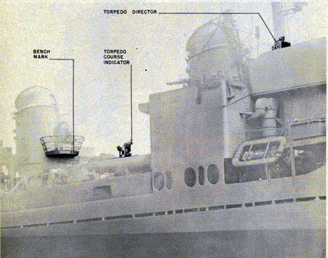
related torpedo fire control mechanisms. See figure 3.
Figure 3-View of modern destroyer showing location of torpedo director,
torpedo course indicator and bench mark.
5
TORPEDO FIRE CONTROL EQUIPMENT (DESTROYER TYPE) OP 1586
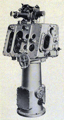
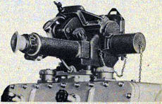
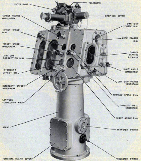
Figure 4-Front right view of Torpedo Director Mk 27 Mod 5.
What the Instruments Are
The torpedo director, see figure 4, is a fire control instrument which computes torpedo course
relative) and transmits electrical torpedo course orders and gyro angle orders to the torpedo
course indicators at the torpedo tube mounts. A firing key at the director when closed completes
the firing circuit which launches the torpedo on its run to the target.
Where the Instruments Are Used.
The torpedo director and the torpedo course indicators are used in the torpedo fire-control
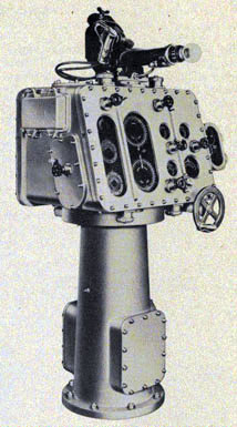
Figure 5-Front left view of Torpedo Director Mk 27 Mod 5.
system of modern destroyers. On destroyers having only one director, the director is mounted
on the centerline of the signal bridge forward of the Gun Director Mk 37. When two torpedo
directors are used, they are mounted in the wings of the signal bridge, one on the port and one on
the starboard side. A torpedo course indicator is mounted on each of the torpedo tube mounts. See figure 3.
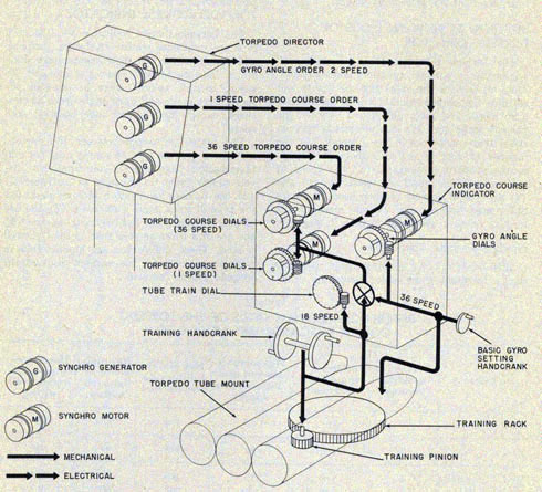
What the Instruments Do
The Torpedo Director Mk 27 produces, by electrical and mechanical means, torpedo
6
INTRODUCTION
course and transmits torpedo course orders and gyro angle orders electrically to the torpedo
course indicators. See figure 11. At the torpedo tube mount, the torpedo tubes are trained until
the torpedo course and gyro angle dials of the indicators are matched. When these dials are
matched, the tubes are trained correctly and actual tube train can be read directly from the tube
train dial of the torpedo course indicator.
In actual operation, the torpedo director mechanically computes basic sight angle from the
torpedo-speed triangle, corrects it for torpedo creep (latitude correction) and then combines
the corrected sight angle with relative target bearing to produce basic torpedo course. The basic
sight angle can be modified at the director to change the point of intercept without changing the
problem set-up. The basic torpedo course can also be modified at the director for tube offset to
produce torpedo course.
The tube offset provides a spread angle between the two torpedo tube mounts on the ship and
should not be confused with the spread gyro angle set on the torpedoes of a given tube mount.
Synchro generators in the torpedo director continuously transmit (electrically) torpedo course
at one-and 36-speed and gyro angle at two-speed to the torpedo course indicators at the torpedo
tube mounts. Dials at the torpedo director show the values of all the quantities entering in the
torpedo fire control problem and the values of torpedo course and gyro angle transmitted to the
torpedo course indicators.
The torpedo course and gyro angle signals are received by synchro motors in the torpedo course
indicators. These motors position the inner dials of follow-the-pointer dial groups. The gyros
in the torpedoes are set properly by turning the basic-gyro-setting hand crank at the tube
mount until the gyro angle dials are matched. The torpedo tube mount is properly trained by
turning the training hand crank at the torpedo tube mount until the one-and 36-speed torpedo
course dials are matched. The torpedo tubes are correctly aimed when the torpedo course and
gyro angle dials are matched with the signals transmitted from the torpedo director.
HOW THE DIRECTOR SOLVES THE TORPEDO FIRE TRIANGLE
Basically, the job of the director is to solve or produce the required relative torpedo course for
firing torpedoes to hit the target. As shown in figure 146, torpedo course (relative) depends
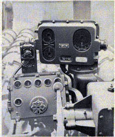
upon two quantities: (1) relative target bearing and (2) basic sight angle corrected for
Figure 6-Torpedo Course Indicator Mk 1 Mod 4 installed on torpedo course attachment, quintuple tube mount.
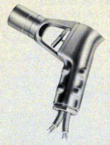
Figure 7-Telescope Mk 50 Mods 0 and 1.
7
TORPEDO FIRE CONTROL EQUIPMENT (DESTROYER TYPE) OP 1586
Figure 8-Firing Key Mk 19 Mod 0.
latitude correction. Of these quantities, basic sight angle is the only unknown one, therefore, the
director must solve for this basic sight angle before torpedo course can be determined.
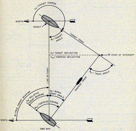
Theoretically, the problem involved is to solve the triangle of torpedo fire.* See figure 9. In
this triangle, the line of sight from own ship to target forms the base of the triangle. The
length
of this line is proportional to the range of the target. The target track and torpedo track form
the other two sides of the triangle. Since the lengths of torpedo track and target track are
proportional to the torpedo and target speeds respectively, these lines may be considered as
representing torpedo and target speeds. Therefore, for a given target angle, the torpedo will
intercept the target at point M. (This occurs, as shown in figure 9, when Xt (target deflection)
is equal to Xto (torpedo deflection).
Xt = St Sin Bt
Xto = Sto Sin Ds
Thus, to secure a hit, Xt must equal Xto, when St Sin Bt Sto Sin Ds. From the above equation,
Ds (basic sight angle) can be found, since the three remaining quantities (St, Bt and Sto) are known.
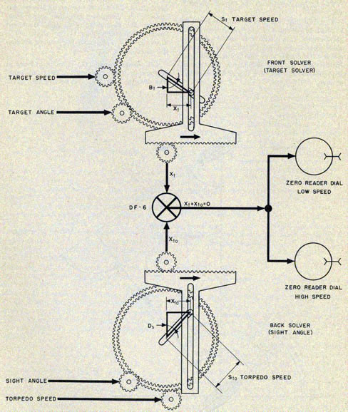
The torpedo director handles the problem in the form of the equation given above. Basic
sight angle is computed in the director by the operation of the two component solvers, front and
back, see figure 10. The front solver (target solver) from inputs of target course, target
speed,
own ship course and relative bearing produces Xt (target deflection component). The back
solver (sight angle solver), with an input of torpedo speed, is rotated through an angle of Ds
(sight angle) by the sight angle follow-up motor or the sight angle hand crank, until its output
Xto (torpedo deflection) equals Xt. When Xt equals Xto, the high-and low-speed zero reader dials
in the torpedo director are at zero. If these dials are off, they indicate that the Xt and Xto are not
equal and that the correct sight angle has not been produced. For a more detailed description of
how the torpedo director works, see chapter 3.
*To simplify the explanation and understanding of the torpedo fire-triangle problem, gyro
angle, latitude correction, intercept offset and tube offset were omitted. However, in actual
solution of the problem in the torpedo director, these quantities are taken into consideration
in producing torpedo course orders.
INPUTS AND OUTPUTS
The Torpedo Director Mk 27 has two electrical inputs, ten hand inputs, and two electrical
outputs. See figure 146.
Electrical Inputs
One electrical input received by the director is own ship course (Co). It is received
continuously at one-speed from the gyro compass system, and positions the one-speed own ship
course zero reader dial. In case of power failure, own ship course can be introduced into the
director by hand, see Hand Inputs below.
The other electrical input, relative target
bearing (Bs), is received at one-and 36-speed by the bearing receiver on the right side of the
torpedo director. This electrical signal positions the inner dials of the one-and 36-speed follow-
the-pointer dial group of the bearing receiver. The ring dials of the two dial groups are turned
mechanically to match the inner dials by manually rotating the training handwheel of the torpedo director.
8
INTRODUCTION
Hand Inputs
The 11 hand inputs to the torpedo director are:
(1) Own ship course (Co) is introduced by hand at 180-speed or 2 degrees per revolution of the hand
crank. This quantity is introduced manually when there is power failure to the servo motor of
the own ship course follow-up unit. In this case, the own ship course hand crank is turned to
keep the zero reader dial matched at zero.
(2) Target speed (St)is introduced by hand
at 10-speed or 2 knots per revolution of the
hand crank. The director personnel receive this quantity by telephone from the ship's main plot
or CIC. This quantity positions the speed spiral of the front solver (target solver). The target
speed dial indicates the amount set into the director.
(3) Target course (Ct) is set in by hand at 90-speed or 4 degrees per revolution of the hand crank.
The director operators also receive this quantity
Figure 9-The triangle of torpedo fire.
9
TORPEDO FIRE CONTROL EQUIPMENT (DESTROYER TYPE) OP 1586
Figure 10-Diagram of computer angle solver position after computing fire control problem.
10
INTRODUCTION
by telephone from the ship's main plot or from CIC. The target course input positions the
angle gear of the front solver and the target angle dial.
(4) Torpedo speed (Sto) is introduced by hand at 10-speed or 2 knots per revolution of the
hand crank. This is an arbitrary speed chosen for the torpedo problem set-up. The director is
designed to solve for torpedo speeds from 0 to 50 or 60 knots. This quantity positions the speed
spiral of the back solver and the torpedo speed dial.
(5) Torpedo course (relative) (Bto) is produced in the director by turning the training
handwheel at 180-speed or 2 degrees per revolution for Mods 1, 2, 3, and 7 and at 120-speed or 3 degrees
per revolution of the handwheel for Mods 4, 5, 8, and 9. Rotation of the handwheel positions the
torpedo course synchro generators and the director computing mechanism.
(6) Relative Target Bearing (Bs) (director train plus sight angle) is introduced manually by
turning the director train handwheel until the inner follow-the-pointer dials of the bearing
receiver are matched. Relative target bearing can be obtained optically by training the director
until the telescope bears on the target.
(7) Latitude Correction (Kla) is introduced by hand at 180-speed or 2o per revolution of the
knurled latitude correction wheel. One click equals 10 minutes. The magnitude of the correction
depends upon the duration of the torpedo run and the latitude in which the torpedo is fired. The
latitude correction dial indicates in degrees the amount of the correction introduced in the
director.
(8) Intercept offset (Osi) is introduced by hand at 180-speed or 2 degrees per revolution of the hand
crank. This input, an arbitrary correction, is introduced when it is desired to change the basic
sight angle by some pre-determined value to take care of unexpected target maneuvers. The
changes are made in the basic sight angle directly without altering the problem set-up.
Intercept offset is generally introduced after one or more torpedoes have been fired. The
intercept offset dial indicates the amount of offset introduced in the director.
(9) Tube offset (Otu) is introduced by hand
at 180-speed or 2 degrees per revolution of the hand
crank. Tube offset modifies the torpedo course order so that the forward tube mount is trained
forward and the after tube mount is trained aft, or vice versa through an angle equal to the tube
offset angle with respect to the basic torpedo course. The tube offset dial indicates in degrees the
amount of offset introduced in the director.
(10) Gyro angle (Bgy) is introduced by hand at 72-speed or 5 degrees per revolution of the hand
crank. This input positions the gyro angle dial and the two-speed synchro generator marked "E".
This generator transmits gyro angle electrically at two-speed to the torpedo course indicator at
the forward and after torpedo mounts.
(11) Sight angle (Ds) is introduced by hand at 180-speed or 2o per revolution of the hand
crank. This quantity is introduced manually when there is power failure to the sight angle servo
motor. In this case the hand crank is turned to keep the high-and low-speed zero reader dials at zero.
Outputs
The two electrical outputs of the torpedo director are:
(1) Torpedo course order (Bto) transmitted at one-and 36-speeds by the two sets of synchro
generators. The generator "C" and the generator "A" transmit one-and 36-speed signals
respectively to the torpedo course indicator on the forward torpedo tube mount, generators "B"
and "D" transmit torpedo course to the after torpedo tube mount. See figure 146.
(2) Gyro angle (Bgy) is also transmitted to the torpedo course indicators at the torpedo tube
mounts. It is transmitted at two-speed by the synchro generator "E".
Note: When the operators at the tube mounts turn their hand cranks to match the torpedo course
dials and the gyro angle dials of the torpedo course indicators, they train the mounts correctly
to hit the target and thus produce tube train.
11
TORPEDO FIRE CONTROL EQUIPMENT (DESTROYER TYPE) OP 1586
Table I
DIFFERENCES BETWEEN MODIFICATIONS OF THE TORPEDO DIRECTOR MK 27
Mod
Maximum Torpedo Speed
Number of sets of one-and 36-speed Torpedo Course Synchro Generators
Training Handwheel Speed
Type of Bearing Receiver Used
Remarks
1
50 knots
2 sets
180-speed 2o/Rev.
External lighting type (ORDALT 2107)
2
50 knots
3 sets
180-speed 2o/Rev.
External lighting type (ORDDALT 2107)
No tube offset provided for set of torpedo course generators controlling center torpedo tube mounts. Construction same as Mod 1.
3
60 knots
2 sets
180-speed 2o/Rev.
External lighting type (ORDALT 2107)
Construction same as Mod 1.
4
60 knots
2 sets
120-speed 3o/Rev.
External lighting type (ORDALT 2107)
Similar in appearance and construction to Mod 1. For description of bearing receiver see pages 54 to 61.
5
60 knots
2 sets
120-speed 3o/Rev.
External lighting type (ORDALT 2107)
This is the production instrument. Similar to Mod 4. For bearing receiver see pages 54 to 61.
6
60 knots
2 sets
120-speed 3o/Rev.
None
Experimental director, only one manufactured. Same as Mod 5 except contains square race dial gears.
7*
50 knots
2 sets
180-speed 2o/Rev.
Internal lighting type
Mod 1 torpedo director with a bearing receiver attached, see pages 54 to 61.
8*
60 knots
2 sets
120-speed 3o/Rev.
Internal lighting type
Mod 4 torpedo director with a bearing receiver attached, see pages 54 to 61.
9*
60 knots
2 sets
120-speed 3o/Rev.
Internal lighting type
Mod 5 torpedo director with a bearing receiver attached, see pages 54 to 61.
*NOTE: Mods 7, 8, and 9 were assigned after internal lighting type bearing
receivers were
installed. All ships having these instruments are now in inactive status.
Instrument nameplates
are to be changed from Mods 1, 4, and 5 to 7, 8, and 9, respectively, by
the ship's force at the
time the ships are activated.
12
INTRODUCTION
When tube offset has been set into the director, synchro generators "A" and "C" send out torpedo
course modified for tube offset for the forward tube mount; synchro generators "B" and "D"
transmit torpedo course modified for tube offset for the after tube mount.
DIFFERENCES BETWEEN MODS OF TORPEDO DIRECTOR
The Torpedo Directors Mk 27 Mods 1 to 9 are similar in purpose, function, and operation. They
all require the same type of inputs and all have the same outputs, torpedo course, and gyro
angle. The main differences between the various mods are: (1) the maximum torpedo speed that
can be set in the director, (2) the number of sets of one-and 36-speed torpedo course synchro
generators, (3) the speed of the training handwheel and telescope drive and (4) the type of
bearing receiver used. The main differences between the various mods of the torpedo director
are listed in table 1, page 12.
NavOrd Ordalts Applicable
1255-Instructions for installing centering device for sight angle motor follow-up.
1787-Installation of red illumination for dials.
2107-Installation of relative target bearing receiver.
DIFFERENCES BETWEEN MODS OF THE TORPEDO COURSE INDICATOR
The Torpedo Course Indicator Mk 1 Mods 0 to 4 are somewhat similar in design, purpose, and
function. All the instruments have dials which indicate torpedo course at one-and 36speed,
torpedo course order at one-and 36speed, gyro angle and gyro angle order at two-speed, except
Mod 3, and tube train at one-speed.
The major difference between the various mods are: (1) the type of supply used for dial
illumination (separate six-volt supply or six-volt supply from transformer in instrument),
(2) the number of synchro motors used, (3) the type of gyro angle dials used, (4) the use of
plug boards in the lightwell wiring, and (5) the use of a three-ampere fuse in the lightwell
wiring. These differences are summarized in table 2, page 13 for the various mods of the
torpedo course indicator.
Table 2
DIFFERENCES BETWEEN MODS OF THE TORPEDO COURSE INDICATOR MKI MODS 0 TO 4
Instrument
Number of synchro motors
Receives gyro angle order electrically
Has separate six-volt dial illumination supply
Has dial illumination transformer
Has plug board in lightwell wiring
Has three-ampere fuse in lightwell wiring
Mod 0
3
yes
no
yes
yes
no
Mod 1
3
yes
no
yes
no
no
Mod 2 (original)
3
yes
no
yes
no
yes
Mod 2 (later)
3
yes
yes
no
no
no
Mod 3*
2
no
no
yes
no
yes
Mod 4
3
yes
yes
no
no
no
*The major difference between the Mod 3 and the other indicators is that the Mod 3 is not
provided with the two-speed gyro angle synchro motor and the gyro angle follow-the-pointer
dials. In the Mod 3, the follow-the-pointer dials are replaced with a single gyro angle dial which
indicates gyro angle in degrees set into the gyros of the torpedoes.
735193-47-2
13
TORPEDO FIRE CONTROL EQUIPMENT (DESTROYER TYPE) OP 1586
Figure 11-Functional diagram showing course of inputs and outputs through the Torpedo Course Indicator Mk 1 Mods 0, 1, 2 and 4.
14
Chapter 3
FUNCTIONAL DESCRIPTION
HOW THE TORPEDO DIRECTOR MK 27 WORKS
In this section, the overall internal operation of the Torpedo Director Mk 27 Mods 1 to 9 is
described. For information on how each individual unit of the torpedo director works, refer to
the particular section describing the unit in the Description Chapter.
Figure 146, functional diagram for the torpedo director, shows the path of the various
quantities through the torpedo director. In order to simplify the description of how the director
works, each quantity will be discussed to show its travel through the director and what part it
contributes in producing torpedo course.
Relative Target Bearing
This quantity is received electrically by the one-and 36-speed synchro motors in the bearing
receiver. As shown in figure 146, this quantity positions the inner dials of the follow-the-pointer dial groups. To get the director on the designated target, these dials are matched
against the ring dials by turning the training handwheel.
If all the dials of the director are set at zero, rotation of the training handwheel will: (1)
train
the director case and the telescope as a unit, (2) position the middle dial of main dial group
"A" via differential DF-3 to indicate relative target bearing, (3) position the rotors of two sets
of one-and 36-speed torpedo course synchro generators an amount equal to relative target
bearing, and (4) position the torpedo course dials to indicate this bearing.
In actual operation, this is not the case. Briefly, the input of relative target bearing, introduced
by the training handwheel, is combined with corrected sight angle and tube offset to produce the
torpedo course necessary to hit the target. Therefore, before the correct torpedo course can be
produced, all the necessary
quantities or known factors of the torpedo control problem must be introduced into the torpedo director.
Own Ship Course
This quantity, received electrically at one-speed, positions the own ship course zero reader dial.
In normal operation, rotation of the rotor of the own ship course synchro motor operates the
follow-up mechanism which controls the operation of the servo motor. Rotation of the servo motor, positions the own ship course dial and sends own ship course (Co) to differential DF-2.
Here, own ship course is combined with relative target bearing (Bs) to produce true target bearing (B).
For a complete description of how the own ship course receiver works, see page 45.
True target bearing positions the outer ring dials of the main dial groups "A" and "B" and goes
through differential DF-2.
Target Speed
The target speed crank is turned to introduce the proper target speed in the torpedo director.
Rotation of this crank does two things: (1) it positions the target speed dial which indicates the
amount of target speed set in, and (2) positions the speed gear (spiral-cam plate) of the front
solver. Rotation of the spiral plate positions the pin (cam follower) away from the center of the
plate, a distance proportional to target speed. The intermittent gear limit stop limits target speed input from 0 to 50 knots.
Target Course and Target Angle
Target course (Ct) is introduced into the director by rotation of the target course knob. This
input goes to differentials DF-1 and DF-2 where it is combined with true target bearing to
produce target angle (Bt).
15
TORPEDO FIRE CONTROL EQUIPMENT (DESTROYER TYPE) OP 1586
Target angle positions the middle dial of the main dial group "A" and the angle gear of the
front solver. Rotation of the angle gear drives the output rack, by means of the pin, to produce
target deflection (Xto) which goes to differential DF-6.
Target angle also positions the spiral gear via the compensating differential DF-4. The purpose
of this differential is to prevent the position of the pin from changing as the angle gear is
rotated. For a complete description of the component solver and the compensating differential,
see page 35.
Torpedo Speed
The torpedo speed crank is turned to introduce, through DF-5, the proper torpedo speed (Sto)
into the torpedo director. Rotation of this crank does two things: (1) it positions the torpedo
speed dial which indicates the amount of torpedo speed set in, and (2) it positions, through DF-
5, the speed gear (spiral-cam plate) of the back solver. Rotation of the spiral plate positions
the pin (cam follower) away from the center of the plate a distance proportional to torpedo
speed.
The limit stop limits torpedo speed input from 0 to 50 knots for Mods 1, 2, and 7 and from 0 to
60 knots for Mods 3, 4, 5, 6, 8 and 9.
Torpedo Deflection and Target Deflection
Assuming that the angle gear of the back solver is at its zero position, the output of the
solver,
torpedo deflection (Xto) would be zero. If it were at any other position a certain amount of
torpedo deflection would be produced. This quantity Xto is sent to differential DF-6 where it is
compared with target deflection (Xt). If both quantities are equal, there is no output of the
differential and the high-and-low-speed zero reader dials remain zeroed.
If the two quantities are unequal, the differential algebraically adds the two quantities to
form
an output. This output does two things: (1) it displaces the zero reader dials from their zero
position, and (2) it operates the follow-up mechanism which controls the sight angle servo
motor (telescope train motor) which restores
the zero-reader dials to zero. In other words, the algebraic sum of Xt and Xto equals zero.
Sight Angle
Rotation of the sight angle servo motor produces sight angle which does three jobs: (1) sight
angle via differential DF-9 trains the telescope away from the target an angle equal to the sight
angle, (2) positions the basic sight angle dials, and (3) positions the angle gear of the back
solver, until a value of Xto is produced that is equal to Xt. When Xto equals Xt, the follow-up
mechanism is zeroed and the servo motor stops rotating.
Note: In case of power failure to the servo motor, the sight angle hand crank can be used to take
the place of the servo motor. In this case, the crank must be turned to keep the high-and-low-speed zero reader dials zeroed.
The limit stop switch shown in figure 35, controls the operation of the servo motor when sight
angle is at its extreme limits.
Torpedo Course
Torpedo course is produced when the director trainer turns the training handwheel to bring the
telescope back on the target. Rotation of the handwheel positions the rotors of the two sets of
one- and 36-speed torpedo course synchro generators, the torpedo course dials, and the check dials.
This torpedo course does not include latitude correction, intercept offset or tube offset. These
corrections are introduced into torpedo course as follows:
Latitude Correction
Latitude correction is produced when the latitude knob is turned to set the latitude correction
dial. The correction is introduced in the instrument, when the intercept offset crank is turned
to match the intercept dial with the latitude correction dial.
Intercept Offset
When the intercept offset crank is turned to introduce either latitude correction or intercept
offset, it trains the telescope via differential
16
FUNCTIONAL DESCRIPTION
DF-9 an additional amount equal to the correction and also positions the front and back solvers.
Thus, differential DF-9 combines basic sight angle with this correction to produce corrected
sight angle.
Corrected Sight Angle
This corrected sight angle trains the telescope, and positions the corrected sight angle dial
and the inner dials of the main dial group "A" and "B"
Here again, when the training handwheel is turned to bring the telescope back on the target, the
torpedo course corrected for latitude correction and intercept offset is produced.
Tube Offset
Tube offset is introduced when the tube offset
crank is turned. Rotation of the crank positions the tube offset dial and is transmitted to
differentials DF-7 and DF-8 where torpedo course is modified for tube offset. The outputs of DF-
7 and DF-8 position the torpedo course synchro generators which transmit the torpedo course
corrected for tube offset to the torpedo course indicators.
Gyro Angle
Gyro Angle is produced when the gyro angle crank is rotated to position the gyro angle dials.
Rotation of the crank is transmitted to position the rotor of the gyro angle synchro generator.
This generator transmits gyro angle electrically at two-speed to the torpedo course indicators.
In actual operation of the torpedo director, several of the above operations are going on at the
same time. Therefore, torpedo course is being produced continuously by the torpedo director as
the problem progresses.
HOW THE TORPEDO INDICATOR MK I WORKS
The Torpedo Course Indicators Mk 1 Mods 0 to 4 are similar in purpose and operation. Each
indicator is secured to a torpedo course attachment which is mounted on the top of the torpedo
tube mount. See figure 6.
The purpose of the torpedo course indicator is to enable the tube mount personnel to train the
tube mount and set the gyro angle on the torpedoes in accordance with the electrical torpedo
course and gyro angle orders from the director.
Inputs
The indicator has four inputs: (1) torpedo course received electrically at one- and 36-speed,
(2) gyro angle received electrically at two-speed, (3) tube train received mechanically at 18-speed and, (4) gyro angle received mechanically at 36-speed. See figure 11.
The indicator is equipped with dials to show torpedo course, gyro angle, and tube train.
The Torpedo Course Indicator Mk 1 Mod 3 is equipped with only two synchro motors which receive torpedo course. The Mod 3 indicator does not receive gyro angle electrically.
Figure 11, functional diagram of the Torpedo Course Indicator Mk 1 Mods 0, 1, 2, and 4,
illustrates the path of inputs through the instrument.
1. Torpedo course received electrically at one- and 36-speed, positions the inner dials of the
torpedo course follow-the-pointer dials.
2. Gyro angle received electrically at two-speed positions the inner dial of the gyro angle follow-the-pointer dial.
3. Gyro angle received mechanically at 36speed from the gyro setting mechanism performs two
actions: (1) it positions the ring dial of the gyro angle follow-the-pointer dials to match the
inner dial, and (2) it forms one input to the differential. When the gyro angle dials are matched
the gyros in the torpedoes are properly set.
4. Tube train received mechanically at 18speed from the tube mount rack as the mount is
trained, also results in: (1) positioning the tube train dial to indicate the actual train of
the tube mount, and (2) forming the other input to the differential. The differential algebraically
adds gyro angle to tube train to produce torpedo course.
Torpedo course, output of the differential, mechanically positions the ring dials of the
17
TORPEDO FIRE CONTROL EQUIPMENT (DESTROYER TYPE) OP 1586
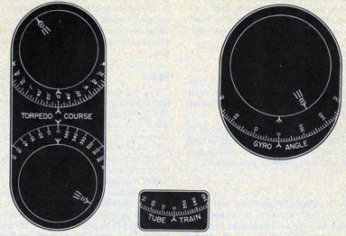
Figure 12-Appearance of Torpedo Course Indicator dials alter torpedo course and gyro angle orders have been received from the torpedo director.
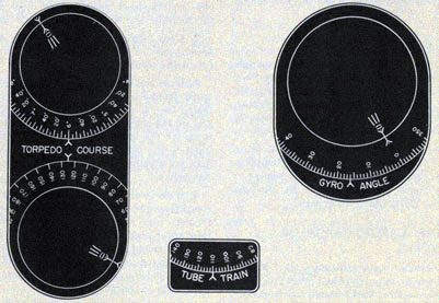
Figure 13-Appearance of Torpedo Course Indicator dials after tube mount has been trained to
execute torpedo course order and gyro angle has been properly set on torpedoes.
18
FUNCTIONAL DESCRIPTION
torpedo course follow-the-pointer dials to match the inner dials. When the torpedo course dials
are matched, the torpedo tube mount is properly trained. See figure 13. To operate the indicator
properly the gyro angle dials and the torpedo course dials must be kept matched at all times in
order to launch the torpedoes on the correct course.
How to Read the Dials of the Indicator
The Torpedo Course Indicator Mk 1 Mods 0, 1, 2, and 4 is equipped with three sets of dials: (1)
the one- and 36-speed torpedo course follow-the-pointer dials, (2) gyro angle follow-the-pointer dials, and (3) the tube train dial.
The Torpedo Course Indicator Mk 1 Mod 3 is also equipped with three sets of dials. However,
unlike the other mods the gyro angle dial is a single mechanically driven dial that indicates
the amount of gyro angle set into the torpedoes.
Torpedo Course Dials. The torpedo course dials consist of an inner dial, positioned by torpedo
course received electrically from tie torpedo director, and a ring dial positioned mechanically
by the output of the differential in the torpedo course indicator.
Figure 12 illustrates how the dials appear when the torpedo course indicator is receiving a
typical torpedo course order from the director. Observe that the inner dials have moved away
from their zero position and that their indexes are not in alignment with the indexes of the ring
dials. This indicates that the torpedo tube mount has not been trained to carry out the order.
Figure 13 illustrates how the dials appear when the torpedo tube mount has been trained to
execute the torpedo course order. The indexes of the ring dials match the indexes of the inner
dials. The ring dials when read against the fixed indexes show that the torpedo course order
received from the torpedo director is 126 degrees. As illustrated, the one-speed dial indicates
approximately "120" degrees and the 36speed dial indicates "6" degrees. Therefore, the exact
reading is 126 degrees.
Gyro Angle Dials. The gyro angle dials of the Torpedo Course Indicator Mk 1 Mods 0, 1,
2, and 4 consist of an inner dial, positioned by gyro angle order, received electrically from
the torpedo director, and a ring dial positioned mechanically by the basic gyro setting hand crank.
Figure 12 illustrates appearance of the dials when the indicator is receiving a typical gyro
angle order from the torpedo director. Observe that the inner dial is away from its zero position
and that the index of the inner dial is not in alignment with the index of the ring dial.
Figure 13 shows how the dials appear when the basic gyro setting hand crank has been turned to
match the index of the ring dial with the index of the inner dial. When the dials are matched, the
gyros are properly set in the torpedoes. The reading of the ring dial against the fixed index
indicates the gyro angle is 16 degrees.
The single gyro angle dial of the Mod 3 indicator is positioned mechanically by the rotation of
the basic gyro angle hand crank of the gyro setting mechanism. The graduations on this dial are
the same as those on the gyro angle dial for Mods 0, 1, 2, and 4. The Mod 3 dial indicates in
degrees the gyro angle set on the gyros in the torpedoes.
Tube Train Dial. This dial is positioned mechanically, degree for degree, as the torpedo tube
mount is trained. The tube train dial indicates the actual train of the torpedo tube mount
relative to own ship.
Figure 13 illustrates the appearance of the dial when the torpedo tube mount is trained 110 degrees.
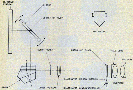
HOW THE TELESCOPE MK 50 WORKS
The main purpose of the telescope is to enable the director trainer to train the director on a
visible target and to keep the director trained on the target as corrected sight angle is being
produced in the director. See figure 7.
The Telescope Mk 50 Mod 0 and 1 is of the tilting mirror type. As the ship rolls and pitches the
line of sight is kept on the target by means of the mirror elevating knob which positions the
mirror in the telescope. Figure 14 is a schematic diagram of the telescope. This view shows the
path of light through the lens system.
19
TORPEDO FIRE CONTROL EQUIPMENT (DESTROYER TYPE) OP 1586
The ray filters in the telescope are shifted by rotation of the ray filter knob mounted on the top
of the telescope. The ray filters provided are "CLEAR", "RED", "YELLOW", "LIGHT NEUTRAL",
and "DARK NEUTRAL". The crosslines of the telescope are illuminated by
means of a lamp. The intensity of the crossline illumination is controlled by the crossline
illumination rheostat mounted on top of the torpedo director case. This rheostat provides for
three conditions "DIM", "OFF", and "BRIGHT".
Figure 14-Telescope Mk 50 optical diagram.
20
Chapter 4
OPERATION
The operation procedure and related information presented in this chapter are compiled from
current standard destroyer doctrine and should serve as a guide which can be varied according to
type of ship, personnel available, material conditions and the ship's doctrine set down by the
ship's commanding officer.
PERSONNEL REQUIRED
Theoretically, the Torpedo Director Mk 27 Mods 1 to 9 can be operated by two men, but in
actual operation three or four men are used. They are: (1) torpedo officer, (2) director
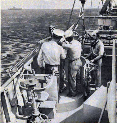
trainer, (3) selector switch operator, and (4) telephone talker. See figure 15.
Figure 15-Torpedo officer, director trainer and telephone talker operating torpedo director.
21
TORPEDO FIRE CONTROL EQUIPMENT (DESTROYER TYPE) OP 1586
Torpedo Officer
The torpedo control officer is responsible, under the commanding officer, for the efficient
operation and maintenance of the torpedo control system and the torpedo battery. The torpedo
control officer will see that firing and synchro transmission circuits are tested frequently.
His station is at the engaged torpedo director. He is usually free to consult with the commanding
officer concerning favorable track angles, unmasking the battery, and torpedo speed settings.
When firing torpedoes from both sides of the ship, by utilizing both torpedo directors, the
officer of the deck and the director trainer man one torpedo director and the torpedo control
officer and the selector switch operator man the other.
When the target is designated by the commanding officer, the torpedo officer's usual duties are:
1. Orders "Torpedo action port (starboard)". Designates the target and approximate bearing to the director trainer and tube personnel.
2. Orders type of fire, bridge control or local control. Director control is further indicated by
order, "Match pointers".
3. Orders depth setting in feet.
4. Informs director trainer and tube personnel of number of torpedoes in spread, torpedo speed, unit of
spread, and tube mount offset.
Note: Speed setting is the commanding officers decision.
5. Informs director trainer of target course and speed.
6. Informs tube personnel of target angle and speed.
7. Checks tube train and gyro angle to insure firing on safe bearing and maintains control of gyro angle
at the director. Note: The torpedo officer must know the gyro angle setting so
that he can select the proper intercept offset and torpedo speed corrections.
8. Orders re-adjustment, if necessary, for director set-up.
9. Makes sure that the target is within the effective range.
10. Reports, "On target", to commanding officer. When directed by commanding officer,
orders "stand-by" then "Fire one", "Fire two", etc.
11. Orders "Selective aim, right to left (left
to right)" so the director trainer can choose firing points in the order given. In addition to the
above, he also keeps the tube personnel informed of:
1. The relative bearing and appearance of the target.
2. The target angle and speed.
Director Trainer
The director trainer mans the torpedo director and its firing key on the engaged director. In
actual operation of the torpedo director, the director trainer performs the following duties:
1. Sets torpedo speed, target speed, and target course into the torpedo director.
2. He trains the torpedo director on the target by looking through the telescope and turning the
training handwheels until the crosslines bear on the target. He can also train the director on
an invisible target by turning the training handwheel to match the dials of the bearing receiver.
3. Sets gyro angle into the torpedo receiver as ordered.
4. Makes any other setting or correction as directed.
5. Makes reports such as: "Director set";
"On target" or "On radar bearing"
6. Fires torpedoes with firing key as directed with three second intervals.
Selector Switch Operator
The selector switch operator, at the director, operates the selector and firing switches. He
operates own ship course hand crank in case of power failure. The following duties are
performed by the selector switch operator:
1. Maintains immediate contact over the telephone with the torpedo tube mount operators.
2. Relays, by telephone, target designation, target angle, target speed, torpedo speed, depth
setting, unit of spread, and tube offset to the torpedo tube mounts.
3. Informs the tube mount operators of the number of torpedoes in salvo.
22
OPERATION
4. Operates selector firing switches, reporting by telephone, to the tube mounts, "Fire one, fire two", etc.
Telephone Talker
Serves as torpedo control officer's talker and performs duties of trainer and selector switch
operator in case of casualties to personnel.
For a complete description of the duties of the various operators used in the torpedo control
system, see current D.T.B. (confidential) "Destroyer Torpedo Doctrine and Manual of Torpedo
Control".
HOW TO READ THE DIALS OF THE TORPEDO DIRECTOR
To simplify the understanding of the dial readings and what they represent, a typical torpedo
control problem is given below. Dial readings are illustrated and an explanation of the values
they represent in the torpedo control problem is given.
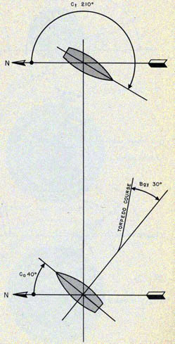
For example, take the problem of a destroyer, which is on course 40 degrees when an enemy ship is
sighted at a range of approximately 6,000 yards. The estimated target course and speed are
210 degrees and 30 knots respectively. See figure 16. The torpedo control officer orders tube mount
personnel to "Standby" for curved fire with a spread gyro angle of 4 degrees between torpedoes.
He also may decide to use a 30 degrees gyro angle, a 10 degrees tube offset and a torpedo speed of 40 knots.
These values are immediately cranked into the starboard torpedo director by the director trainer.
The director trainer also cranks into the torpedo director the target course (210degrees) and the
target speed (30 knots) as relayed to him by the torpedo control officer.
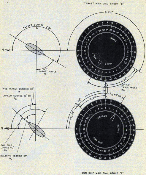
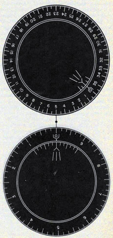
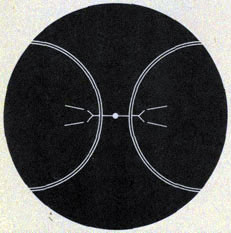
Main Dial Groups
Figure 17 illustrates the torpedo problem as it now appears on the main dial groups. The fixed
straight line joining the centers of the main dial groups represents the line of sight. Both outer
ring dials have a zero degree graduation which indicates true north. These dials
are positioned by true target bearing. Note: True target bearing is made up of own ship course
and relative target bearing. The outer ring dial of the dial groups "A" when read against the
fixed index indicates the true target bearing. In this case, the dial indicates a true target bearing of
"90 degrees", that is, the angle between the north and the line of sight to the target, measured clockwise from the north.
Figure 16-Typical torpedo problem.
23
TORPEDO FIRE CONTROL EQUIPMENT (DESTROYER TYPE) OP 1586
Figure 17-Main dial group of torpedo director.
24
OPERATION
The middle ring dials of dial groups "A" and "B" have the outline of a ship engraved on them.
When the middle ring dial zero index (bow of ship) of the dial group "A" is read against the
outer ring dial, it indicates own
ship course; "40 degrees" for this set-up. When the middle dial is read against the fixed index, it indicates a
relative bearing of "50 degrees". When the zero index of the middle ring dial of the "B" group is read
against the outer ring dial, it
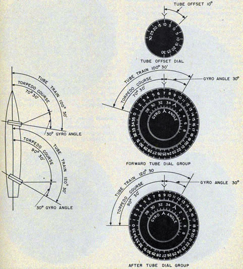
Figure 18-Appearance of tube offset and tube dials.
25
TORPEDO FIRE CONTROL EQUIPMENT (DESTROYER TYPE) OP 1586
indicates a true target course of "210 degrees". When this middle dial is read against the fixed index it
indicates a target angle of "60 degrees".
The center dials of the dial groups "A" and "B" are positioned mechanically by the corrected
sight angle that is produced within the director. Note: Corrected sight angle cannot be read
directly from these dials, but it can be obtained by reading the sight angle dials, see figure 22.
The center dial of group "A", when read against the middle ring dial, indicates a relative torpedo
course (uncorrected for tube offset of 80 degrees-30'). True torpedo course can be obtained by reading
this dial against the outer ring dial. In this case, the reading is 120 degrees-30'. When the center
dial of group "B" is read against the middle ring dial, it indicates a track angle of 90 degrees-30'.
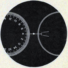
Tube Offset and Tube Dials
Figure 18 illustrates the three dial groups to the left of the main dial groups of the torpedo
director. The upper dial, the tube offset dial, indicates a reading of "10 degrees" tube offset
(starboard)
as ordered by the torpedo control officer. The remaining dial groups are for the tubes. The
upper group is for the forward torpedo tube mount and the bottom group is for the after torpedo tube mount. The center dial of
each of these groups is a fixed dial and serves as an index for the middle or gyro angle dial.
The middle dial is positioned mechanically by the gyro angle hand crank and indicates the gyro
angle setting to he made on the torpedoes. In this setup, the middle dials when read against the
index of the center dial, indicate a reading of "330 degrees". The outer ring dials indicate the torpedo
course order transmitted to the torpedo course indicators at the tube mounts. Note: This torpedo
course order includes tube offset. Therefore, with a tube offset of 10 degrees
(starboard) the torpedo course dial (upper dial group) for the forward torpedo tube mounts
reads 70 degrees-30' and the dial for the after torpedo tube mount reads 90 degrees-30'.
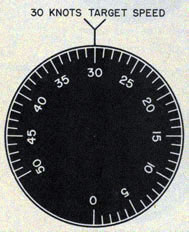
Target Speed Dial
The target speed dial, located to the right of the main dial groups, is graduated every knot and
numbered every 5 knots from 0 to 50. Figure 19 illustrates the appearance of the dial when 30 knots target speed has been cranked into the director.
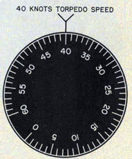
Torpedo Speed Dial
The torpedo speed dial, located to the right of the target speed dial, is graduated every knot
and numbered every 5 knots from 0 to 60
Figure 19-Target speed dial.
Figure 20-Torpedo speed dial.
26
OPERATION
Figure 21-Latitude correction and intercept offset dial.
Figure 22-Corrected sight angle.
knots. For Mods 1, 2, and 7 the dials are graduated from 0 to 50 knots. Figure 20 illustrates
how the dial appears when 40 knots torpedo speed has been introduced.
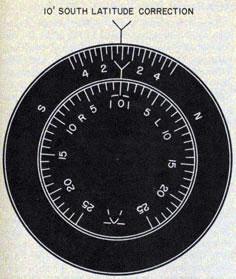
Intercept Offset and Latitude Correction Dial Group
The above dials, located beneath the target speed dial, consist of an inner and outer dial.
Figure 23-Relative target bearing dials.
27
TORPEDO FIRE CONTROL EQUIPMENT (DESTROYER TYPE) 1586
The outer dial is the latitude correction dial, and the inner ring dial is the intercept offset
dial. Figure 21 illustrates the dial readings when 10' south latitude correction and zero degrees
intercept offset have been cranked into the torpedo director.
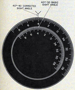
Sight Angle Dials
The sight angle dials, located beneath the torpedo speed dial, consist of an inner and outer dial.
The inner dial is positioned mechanically by basic sight angle. The outer dial is positioned
mechanically by corrected sight angle. Figure 22 shows how the dials appear when 40 degrees 30' basic
sight angle and 40 degrees 40' corrected sight angle have been produced in the torpedo director.
Relative Target Bearing Dials
The relative target bearing dials, located in the bearing receiver, consist of a one- and 36-speed follow-the-pointer dial group. Each set of dials consists of an inner dial, positioned by the
electrical target bearing signal, and an outer dial, positioned mechanically to match the inner dial. Figure 23 illustrates the appearance of the dials when the instrument receives a relative
target bearing of 50 degrees and the director has been trained to match the order.
Zero Reader Dials
The zero reader dials, located on the right side of the director case, consist of high- and low-
speed dials which are positioned mechanically by the difference between Xt and Xto. When Xt
equals Xto, the dials are zeroed as shown in Figure 24. These dials are automatically zeroed by
the follow-up mechanism in the director. In case of power failure to the follow-up mechanism,
the dials are maintained at zero by turning the sight angle hand crank.
Own Ship Course Dials
The own ship course dials, also located on the right side of the director case, consist of a zero
reader dial mounted on the rotor of the own ship course synchro motor and a one-speed dial
which is driven mechanically by own ship course gearing in the director. In normal operation,
the zero reader dial and the one-speed dial are positioned automatically by the own ship course
follow-up unit in the director. In case of power failure to the follow-up unit, the own ship
course hand crank must be turned to keep the zero-reader dial continuously matched at zero.
Figure 25 illustrates how the dials appear when the torpedo director is receiving an own ship
course signal of 40 degrees.
Figure 24-Zero reader dials.
Figure 25-Own ship course dials.
28
OPERATION
SOURCE OF INFORMATION FOR INPUTS
The commanding officer informs evaluators in CIC and the torpedo control officer of: (1) target
by type and true bearing, (2) number of torpedoes to be fired, (3) torpedo speed setting to be
used, and (4) the firing point.
Evaluators in CIC inform both the commanding officer and the torpedo control officers of: (1)
best estimate of target course and speed (from information obtained from DRT, main battery
plot, radar, and from other sources or the mean value of all sources), (2) present range, (3)
estimate of time when target will come within effective range for each torpedo speed, (4) when
target comes within effective range at each torpedo speed, (5) when target has gone outside of
effective range for each speed, and (6) furnishes relevant corrections for intercept offset and
torpedo speed.
Relative target bearing obtained electrically from CIC is indicated on the inner dials of the
bearing receiver. The director is trained on the target when the director trainer turns the
training handwheel to match the bearing receiver dials. If the target is visible, the director
trainer can pick up the target by turning the training handwheel until the vertical crossline of
the telescope intersects the target.
Own ship course is received electrically by the torpedo director where a follow-up mechanism
converts it automatically into a mechanical input. In case of power failure, the own ship course
zero reader dial must be set at zero by means of the own ship course hand crank.
OPERATION ROUTINE
This section will outline a suggested operation routine for putting the torpedo director into
operating condition. This routine may vary somewhat with different ships depending upon ship's
doctrine. In the following outline, the numbers in parentheses refer to the hand cranks that are
numbered correspondingly in figure 147.
1. After removing the tarpaulin cover, set in latitude correction, each morning, by turning the
latitude correction knob (1). This can be done by the officer with the morning watch.
75193-47-3
2. Turn on the power supply to the director and the torpedo control system at the fire control
switchboard. Also, turn on the director heater supply.
3. Turn the bridge transfer switch to "PORT" or "STARBOARD".
4. Turn the director selector switch to "ON" and illumination switch to "TRANSFORMER".
The torpedo director is now ready to track a target. In setting up a problem on the torpedo
director, the following procedure is suggested:
1. Train the director on the target by turning the training handwheel (2) to match the dials of
the bearing receiver or to bring the telescope sight to bear on the target.
2. Set the sight angle crank (3) and the own ship course hand crank (4) to "OUT" position.
Note: In case of power failure, these hand cranks should be left in the "IN" position. As the
problem progresses, the own ship course hand crank must be turned to keep the zero reader dial
at "0" and the sight angle hand crank must be turned to keep the high and low speed zero reader
dials matched at "0".
3. Introduce tube offset by turning the tube offset crank (5).
(4) Introduce refined latitude correction by turning the knob (1) to correct for torpedo creep.
5. Match the intercept offset dial, with the reading on the latitude correction dial by turning hand
crank (6). Set intercept offset as necessary to correct for torpedo turning circle when firing
shots with large gyro angles.
6. Crank in torpedo speed by turning the torpedo speed hand crank (7).
7. Introduce gyro angle, as directed by the torpedo control officer, by turning the gyro angle
crank (8).
8. Introduce target speed by turning the target speed hand crank (9).
9. Set target course into the director by turning the target course hand crank (10). Then train
director on target using the telescope sight or by matching the dials of the bearing receiver.
10. Fire the torpedoes, as directed, by closing the firing key (11).
The following procedure is suggested for securing the torpedo director:
29
TORPEDO FIRE CONTROL EQUIPMENT (DESTROYER TYPE) OP 1586
1. Train the torpedo director to its stowed position, relative bearing
2. Set all the dials of the torpedo director to zero by turning the various hand cranks.
3. Turn the director selector switch and the illumination switch to "OFF".
4. Turn the bridge transfer switch and the heater switch to "OFF".
5. Turn off the power to the torpedo director at fire control switchboard.
6. Cover the torpedo director with tarpaulin provided.
Figure 26-Front right view Torpedo Director Mk 27 Mod 5.