DEPTH CHARGE PISTOL MARK 6 MOD. 2 AND BOOSTER EXTENDER MECHANISM
MARK 6 MOD. 2 - INFORMATION AND INSTRUCTIONS
ILLUSTRATIONS:
Fig.
Page
1
- BuOrd Dr. No. 423548
- 68h
2
- BuOrd Dr. No. 423549
- 68i
3
- BuOrd Dr. No. 433979
- 68j
4
- BuOrd Dr. No. 432885
- 68k
5
- BuOrd Dr. No. 452775
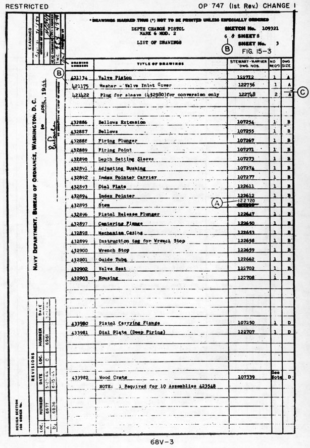
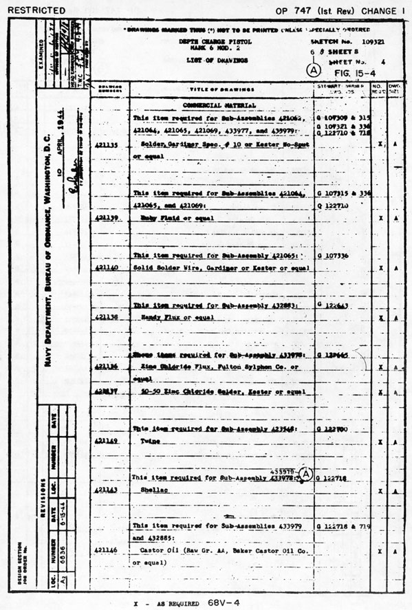
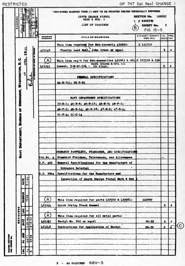
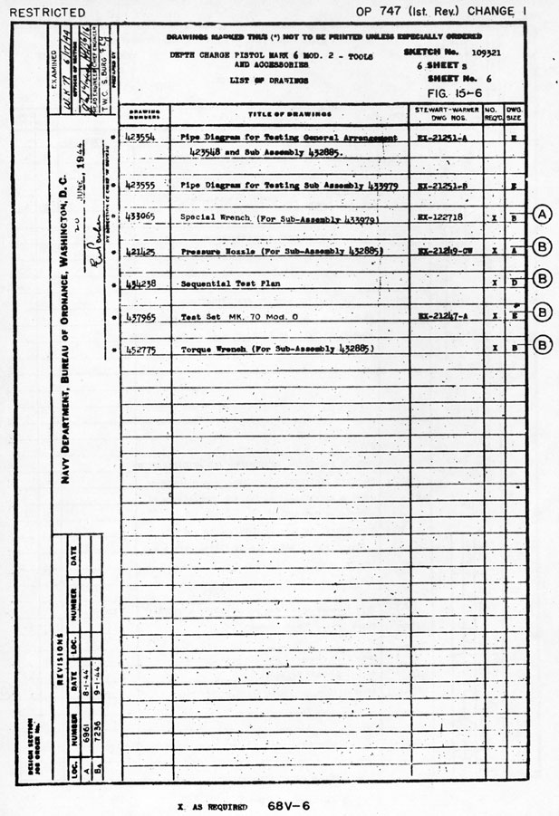
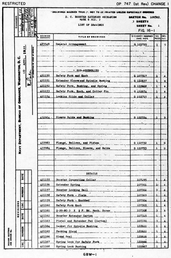
- 681
6
- BuOrd Dr. No. 433065
- 68m
7
- BuOrd Dr. No. 432883
- 68n
8
- BuOrd Dr. No. 421073
- 68o
9
- BuOrd Dr. No. 432893
- 68p
10
- BuOrd Dr. No. 421098
- 68q
11
- BuOrd Dr. No. 432904
- 68r
12
- BuOrd Dr. No. 433984
- 68s
13
- BuOrd Dr. No. 433983
- 68t
14
- BuOrd Dr. No. 421151
- 68u
15-1 to 6
- BuOrd Sk. No. 109321
- 68v-1 to 6
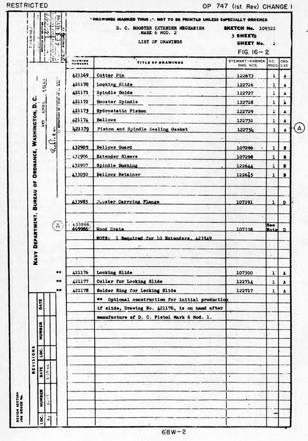
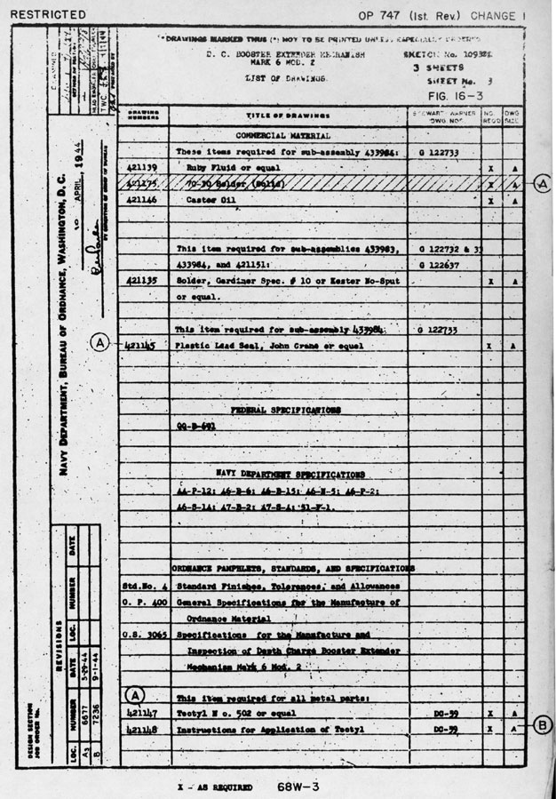
16-1 to 3
- BuOrd Sk. No. 109322
- 68w-1 to 3
1. Pistol Mk 6 Mod 2, Figure 1, is a modification of the basic hydrostatically operated
Mk 6 type. It has a depth setting range of 30 to 1000 feet. It is issued for use, with Booster Extender Mechanism Mk 6 Mod 2, in Depth Charge Cases Mk 9 Mods 2 and 3. Standard detonator and booster components, previously described, may be used interchangeably with the Pistol and Booster Extender Mechanism Mk 6 Mod 2 to make up a depth charge assembly.
2. The Depth Setting Range of the pistol is carried on two dials. The outer dial, stamped
on the pistol flange, provides for index pointer settings of 30, 50, 75, 100,150,200, 250, 300 and "Safe." The inner dial plate, attached to the deep firing mechanism, provides positions for valve settings from 350 to 1000 feet, in 50-foot intervals, and the designation "0-300." The depth setting feature of this pistol is similar to the Pistol Mk 6 Mod 1.
3. Pistol firing at shallow depth settings (30, 50, and 75 feet) is a function of the
time required for water to enter the pistol hydrostatic chamber through the passages of the deep firing mechanism even though the pistol is operated by hydrostatic pressure. In this respect the deep firing mechanism valve of the Pistol Mk 6 Mod 2 is designed to accomplish more rapid filling of the pistol chamber than is obtained in the Pistol Mk 6 Mod 1. Consequently the firing of Pistol Mk 6 Mod 2 will conform more closely to the shallow depth settings noted. Data on depth settings vs. firing time are noted in paragraph (7).
4. The Safe Setting feature of the Pistol Mk 6 Mod 2 may be relied upon to prevent firing of the pistol due to accidental operation of the parts normally functioned by hydrostatic pressure. Firing of Pistols Mk 6 and Mk 6 Mod 1, when set on "Safe" and attached to depth charges which were accidentally subjected to hydrostatic pressure by sinking of the ship carrying them, has been reported. Both laboratory and sea tests conducted during the development of the Pistol Mk 6 Mod 2 disclosed that pressure equivalent to depths of 1000 to 1500 feet would, in some instances, produce distortion of the spring engaging collar and elongation of the piston stem, of Pistols Mk 6 and Mk 6 Mod 1, sufficient to fire the pistol when the index pointer was set on "Safe." This defect has been overcome in the Pistol Mk 6 Mod 2 by the installation of critical parts of suitable strength.
5. In this connection, the Safety System of a depth charge fitted with Pistol and Booster
Extender Mechanism Mk 6 Mod 2 is based upon the ruggedness of the pistol parts to prevent firing of the detonator at a pressure which is greater than the pressure required to rupture either the pistol bellows or the booster extender bellows. A 3/8-inch hole in the pistol mechanism casing provides a vent into the depth charge case central tube for the surge of water pressure through the ruptured pistol bellows, and thereby prevents this surge from acting on the release plunger to cause firing of the detonator. When the central tube of the depth charge case is flooded by either pistol bellows or booster extender mechanism bellows rupture, the pressure differential required to operate the pistol is removed and the depth charge becomes a dud.
6. New and redesigned appendages as follows are attached to the Pistol Mk 6 Mod 2:
(a) Safe setting lock (spring type) noted in NAVORD OTI M12-43 is furnished with each pistol. This device, with depth setting wrench safety stop and knobbed cover, is secured to the pistol guide tube with twine. When the pistol is assembled in the depth charge case, the safe setting lock and wrench stop should be attached as noted on the instruction tags wired to these parts. If the spring type safe setting lock is lost or damaged, holes in the index pointer lug are provided for use of the wire type safe setting lock noted in this pamphlet.
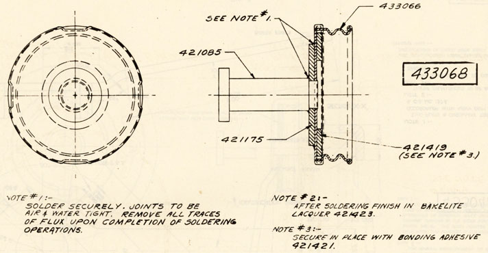
(b) Knobbed safety cover is provided with a more rigid top to insure a complete fracture of the soldered joint when the knob contacts the stripper plate on the. after end of the release track. It is important that the knob be completely wiped from the cover so that a full and unobstructed opening in the cover will be available for the passage of water into the pistol. Both knobbed and plain covers having additional improvements for ease in attaching and removal will be secured to pistols delivered by the contractor beginning about 1 October 1944. The instructions noted in this pamphlet relative to the use, of safety covers should be carried out.
ch1-68b
(c) Detonator holder locking spring has been improved to prevent distortion when withdrawn and replaced before and after the operation of attaching the detonator. The part is shaped to facilitate convenient manipulation by hand or with pliers. The locking spring must be properly attached after the detonator is secured in place as noted in chapter IV of this pamphlet.
7. Depth setting vs. firing time as noted below may be expected when the pistol is installed in the depth charge cases mentioned. Time is measured from the moment the depth charge strikes the water until it explodes. Variation in time is to be expected due to manufacturing tolerances and other causes. As much care as time and circumstances permit should be exercised in making depth settings on the small dial of the deep firing mechanism.
DEPTH CHARGE CASE MARK 9 MODS. 2 and 3
Pistol
Average Time (Sec.) From
Depth Setting
Firing Depth (Ft.)
Track
Projector
30
60
3.5
3.0
50
70
3.9
3.4
75
85
4.7
4.2
100
5.3
4.8
150
7.5
7.0
200
9.7
9.2
300
14.1
13.6
400
18.5
18.0
500
22.9
22.4'
600
27.3
26.8
700
31.7
31.2
800
36.1
35.6
900
40.5
40.0
1000
44.9
44.4
8. Preparation of pistol for installation in depth charge case should, in general, be in accordance with the instructions noted in this pamphlet. However, appropriate supplementary instructions as follows should be carried out by authorized personnel in connection with this operation:
(a) Pistols Mk 6 Mod 2 are shipped in substantial wooden boxes, ten pistols to a box. Each pistol is packed in a separate corrugated paper carton. Pistols should be received in the cocked condition, with the plain type inlet valve cover in place, with the index pointer set on "30," and with the depth setting mechanism for deep firing set at "500." One knobbed type inlet valve cover, one wrench stop, and one safe setting lock for each pistol should be attached to the pistol guide tube with twine.
(b) Depress the valve of the deep firing mechanism with tool provided, as noted in NAVORD OCL M1-44. If this tool is not available, one of similar material and size should be made. Care should be taken to see that the tool does not slip off the ball and become jammed between the ball and the valve seat. This circumstance may nick the valve seat and cause the valve to leak.
(c) Set the index pointer on "Safe" with the depth setting wrench. Care must be taken to insure that the index pointer plunger is registered with the depression in the dial plate which coincides with the safe position. This can be determined by noting the motion of the stem of the plunger which projects through the top of the index pointer lug. An audible click may also be noted when the plunger drops into the dial plate depression.
(d) Place the pistol on the deck or on a convenient locker top with the detonator end up. With the thumb and forefinger, or with pliers, withdraw the end of the detonator holder locking spring from the hole in the guide tube. Rotate the spring sufficiently to permit the point to rest on the surface of the guide tube. Remove detonator holder and attach detonator.
(e) If a pistol not in the cocked condition is received aboard ship, set the index pointer on "Safe," depress the valve of the deep firing mechanism, and cock the pistol with a suitable piece of rod or a screwdriver. Repeat the cocking operation several times to make sure that the firing plunger release balls are firmly seated on the beveled edge of the guide tube bushing. An improperly cocked pistol may fire accidentally and cause injury to personnel attaching the detonator, or it may cause the depth charge to be a dud. Then rotate the index pointer counterclockwise from "Safe" to "30" with the depth setting wrench. An improperly assembled depth setting sleeve or a sheared index pointer stop pin can thus be discovered (by firing of the pistol when the index pointer passes the 50 mark) before the detonator is attached to the pistol and before the pistol is installed in the depth charge.
9. Installation of pistol in depth charge case should in general, be in accordance with instructions noted in this pamphlet. Appropriate supplementary instructions as follows apply to Pistol Mk 6 Mod 2:
(a) Locate the safe setting lock with the attaching cap screw and washer in the pistol carrying flange hole adjacent to the "30" dial mark.
(b) Check the operation of the safe setting lock. (See NAVORD OTI M12-43.) The lock will dig into the lug on the index pointer and become jammed if the pointer is not
ch1-68c
properly aligned at "Safe" so that the index pointer plunger registers with the depression in the dial plate at this setting. It may sometimes be necessary to loosen the safe setting lock attaching cap screw for readjustment of the position of the lock pivot bushing to obtain satisfactory operation. The cap screw should be re-tightened when the lock functions as intended.
10. Pistol depth settings should be made as noted in chapter IV of this pamphlet for Pistol Mk 6 Mod 1.
11. Pistol upkeep routine for ships should be carried out as follows:
(a) Daily routine as noted on page 77 of this pamphlet, with appropriate changes to suit Pistol Mk 6 Mod 2.
(b) Weekly routine as noted on page 79 of this pamphlet with appropriate changes to suit the Pistol Mk 6 Mod 2, particularly with respect to attachment of safe setting lock.
12. Maintenance, testing, and repair of Pistols Mk 6 and Mk 6 Mod 1, as noted in this pamphlet, is generally applicable to Pistol Mk 6 Mod 2. The following supplementary information and instructions should be observed in this connection:
(a) The construction of the Pistol Mk 6 Mod 2 is intended to be such as to withstand exposure to weather conditions on decks of ships for a period of three months without harmful effect to the internal operating parts. Therefore, the "Monthly Inspection Test" by Secondary Stations as noted in NAVORD OCL M7-44 for Pistols Mk 6 and Mk 6 Mod 1 is not required for Pistol Mk 6 Mod 2. However, if the three-month service period is not realized and the condition of any pistol indicates that inspections and test should be performed, such material should be turned in to a "Secondary" or "Main Station" for suitable action.
(b) Forces afloat should turn in, quarterly or as soon thereafter as practicable, Pistol Mk 6 Mod 2 to a convenient "Main Station" as defined in NAVORD OCL M7-44 for a "Quarterly Inspection Test."
(c) A torque wrench, Figure 5, will be supplied by the Bureau of Ordnance. This wrench is required by "Main and Overhaul Station" as defined in NAVORD OCL M7-44, to screw the depth setting mechanism for deep firing into place as noted on figure 4. The torque h applied to assemble the mechanism should be not less than 40 60 ft./lbs. nor more than 50 75 ft./lbs. It is intended that the torque applied within the limits noted should produce the desired result of watertightness with a minimum elongation of the mechanism body. The torque wrench should be used with wrench, figure 6, for assembling the deep firing mechanism. The latter wrench is simple and can be fabricated locally by the respective activities.
(d) The air pressure required for Depth Charge Test Set Mk 3 to test and calibrate subassemblies of Pistol Mk 6 Mod 2 should be increased from 300 to 375 psi. Three pressure gauges, each with a range of 0-600 psi, will be furnished by the Bureau of Ordnance to provide for this change. One each of these gauges should be used to record the test set air tank pressure and to record the pressure at the calibrating and/or leakage testing fixture. The third gauge should be used for a periodical check of the accuracy of the working gauges when a gauge tester is not available. When a test program is underway, the gauges should be checked at least twice weekly and oftener if necessary. The working gauges should he maintained at an accuracy of plus or minus two psi within the range of 100 to 350 psi. Pressure application for test and calibration of Pistol Mk 6 Mod 2 and its subassemblies should be controlled so that the gauge pressure rises at the rate of approximately 11.0 psi per second.
(e) The standard deep firing functional test for completely assembled Pistol Mk 6 Mod 2, using pistol testing fixture of Depth Charge Test Set Mk 3, should not be performed at a depth setting of greater than 600 feet. The watertightness feature and construction of the pistol testing fixture make it unsafe for pressures greater than that equivalent to the 600-foot depth setting.
(f) The blade on the screwdriver attachment of the Test Set Mk 3 calibrating fixture should be modified to suit the construction of the deep firing mechanism as shown on figure 3. This is a simple operation and it can readily be performed by activities operating Test Set Mk 3.
(g) When pistol firing plungers are overhauled by a "Secondary" or "Main" station as noted in NAVORD OTI M2-44, burred release plungers should be replaced. Steel release plungers from spare parts should be used for replacement. These may be readily identified by their parkerized (black) finish. Burred release plungers may cause incomplete cocking of the pistol, which would result in accidental firing of the detonator.
(h) The disassembly of the deep firing mechanism, figure 3, of Pistol Mk 6 Mod 2 is performed as follows:
(1) Submerge assembly in water up to a point just below the end surface of the spring adjusting screw and use a small torch to melt the solder which locks the spring retainer nut. Remove this nut. Then melt the solder which locks the spring adjusting screw and remove the screw. The assembly is submerged in water during this operation to dissipate heat, which would have a harmful effect on the gland seal and spring. Both the spring retainer nut and the spring adjusting screw should be removed while the solder is in the molten state.
(2) Remove the spring and spring retainer and valve piston with attached ball valve.
ch1-68d
(3) Remaining parts of the assembly are similar to the corresponding parts of the Pistol Mk 6 Mod 1 and should be handled as noted in this pamphlet.
(i) Bellows replacement must be made with new type thin wall (0.005 in.) thickness bellows. This bellows will be suitably marked for identification when supplied by the Bureau of Ordnance to "Overhaul" stations which are defined in NAVORD OCL M7-44.
(j) Stem, piston, and key subassembly, figure 7, must be used for replacement whenever it is necessary to replace this subassembly during overhaul.
(k) Spring engaging collar, figure 8, must be used for replacement, if such is found to be necessary during quarterly inspection or overhaul.
(1) Dial plate, figure 9, must be used for replacement if such is found to be necessary during quarterly inspection or overhaul.
(m) Plastic gasket, figure 10, must be used for replacement whenever subassembly, figure 4, is broken down.
(n) Assemble the deep firing mechanism, figure 3, as follows:
(1) Screw valve seat (432902) in place against shoulder in housing (432903).
(2) Put dial plate (433981) in place with stop against indicator point on valve seat (432902). Then rotate both dial plate and valve seat clockwise to match holes in dial plate with nearest holes in housing. Insert dial plate locating pin (421099). This pin must be pressed into place and the end of the pin must be flush with the top surface of the dial plate. Remove the dial plate.
(3) Insert gland seal (421093). Use a new gland seal which has been immersed for approximately one hour in raw castor oil (421146).
(4) Screw packing nut (421092) down on gland seal. Packing nut must be screwed down flush with top surface of housing or slightly below it.
(5) Attach dial plate with four self-tapping screws (421094).
(6) Insert piston and ball valve (421069).
(7) Insert spring retainer (421109) and spring (421132).
(8) Assemble spring adjusting screw (421110) and screw it down until it lightly contacts the shoulder on the spring retainer.
(9) With a small chisel, lightly stake the internal thread of the housing adjacent to -one end of the screwdriver slot in the spring adjusting screw. This is done to produce a slight tightness of fit, so that the spring adjusting screw will retain its adjusted lateral position when so placed during the subsequent calibrating operation. The mechanism is now ready for calibration.
(o) Calibrate the deep firing mechanism, figure 3, of the Pistol Mk 6 Mod 2 in the calibrating fixture of Depth Charge Test Set Mk 3 as follows:
(1) Set the pointer to the 700-foot mark and place the mechanism in the calibrating fixture.
(2) Apply water pressure with control valve "C," as shown on diagrams furnished with test set. Allow pressure to increase at the rate of approximately 11 psi per second until the valve opens wide. This can be determined by a sudden rush of water, as compared with a slight trickle which occurs at a few pounds before the actual opening point. The opening pressure should be observed. Then the pressure should be reduced until the valve closes. Complete closing of the valve will be insured by reducing the pressure 50 psi below the point where most of the water flow suddenly ceases.
(3) The valve should open within the range 290 to 315 psi. The valve spring tension should be controlled by turning the adjusting screw to bring the valve opening pressure within the range noted,- while repeating the cycle of pressure application and release.
(4) When the opening pressure within the required range has been obtained, two cycles of pressure application and release should be made without disturbing the position of the adjusting screw. These two valve operating cycles should be made to check the satisfactory opening pressure initially obtained.
(5) On the second valve operating cycle, inspection for leakage at a pressure of 170 psi should be made. In this connection, an amount of leakage not in excess of 10 cu. in. (164 cc) in one minute is considered satisfactory. Leakage greater than this amount is cause for rebuilding the mechanism. The required pressure noted for leakage inspection should be attained by increasing the pressure from 140 psi.
(6) Chattering or vibrating of the valve at a point of opening within the required range as noted indicates an unsatisfactory mechanism. This condition is generally
ch1-68e
caused by defective parts. Precautions should be taken to see that all test apparatus valves in the direct waterline to the test fixture are open wide during this test, because pipe line restrictions may cause valve chattering or vibration.
(p) After the deep firing mechanism has been satisfactorily calibrated to function within the required limits, it should be carefully removed from the calibration fixture in order not to disturb the position of the spring adjusting screw. As soon as practicable, the adjusting screw should be locked in place by soldering - see Note 7, figure 3, to prevent any possibility of change in calibration.
(q) After the spring adjusting screw has been locked in place with solder, the index pointer of the depth setting mechanism should be registered to the column of the letter "T" in the word "FEET" engraved on the dial plate-see figure 3. Retainer nut (421130) should be screwed down on spring retainer (421109) until it is finger tight against the spring adjusting screw (421110). Precautions must be taken to see that the contact surface between the spring adjusting screw and retainer nut is clean and free of any foreign substance. The retainer nut should be locked to the spring retainer by use of a small torch and fine wire solder. This operation should be performed with the mechanism immersed in water as noted in figure 3 and with due care to avoid solder getting into the hole in the spring retainer stem or holes and slots in spring adjusting screw.
(r) Remove dial plate and apply shellac (421143) to surface of housing and put gasket (421091) in place. Apply shellac to top surface of gasket and replace dial plate and secure it with four self-tapping screws (421094).
(s) Upon completion of the operations of locking the spring adjusting screw and the spring retaining nut of the deep firing mechanism with solder, the mechanism should be blown out with air. Set the point against the stop at the 0 - to - 300 position and insert the nozzle of the air hose in the hole on the valve seat for the blowing-out operation.
(t) The depth setting mechanism for deep firing should be assembled with associated parts as shown in figure 4 for a recheck on operation and a test of watertightness in the leakage test fixture of Depth Charge Test Set Mk 3. Torque wrench described in paragraph 12(c) should be used to screw deep firing mechanism into place. The subassembly should comply with the following requirements in order to be considered satisfactory for use:
(1) With the depth setting pointer registered at the 400 mark, the valve opening pressure should be within the range of 150 to 180 psi. Pressure should be applied at the rate of approximately 11.0 psi per second. While the pressure is rising from 0 to valve opening pressure, an examination should be made for leakage through the dial plate gasket or through the, valve. Leakage not in excess of ten cubic inches (164 cc) in one minute is satisfactory.
(2) The valve closing pressure should be within 46 to 90 psi of the pressure at which the valve opened. This closing pressure should be obtained after the valve opens, by a gradual reduction of the applied pressure until the valve snaps closed.
(u) After subassembly, figure 4, has been subjected to recheck and watertightness test, the depth setting pointer should be set against its stop at 0 - to - 300 and the complete subassembly dried off by blowing with an air hose. Then the subassembly should be dipped in rust preventive compound (421147). Following this operation surplus compound should be drained off and the valve blown out as follows:
(1) Place the nozzle (421425) of the air hose in the hole in the valve seat and apply approximately 150 psi air pressure until traces of rust preventive compound can no longer be noted in the air stream which issues from the open end of the depth setting sleeve. Also blow out any traces of rust preventive compound which remain in the cavity surrounding the head of the valve seat.
(2) With respect to the application of rust preventive compound in general, it is important that excessive deposits of compound do not collect around packing glands, in water inlet openings or on parts working with close clearances, such as balls. If these undesirable conditions are allowed to exist, restricted water openings, locked valves, and deteriorated gaskets will result. After treatment with rust preventive compound, subassemblies and parts must be allowed to dry to permit complete evaporation of the compound vehicle. This drying may be accelerated by passing the parts and subassemblies through a steam or hot air type drier at a temperature of 200o F for approximately two minutes. If such driers are used, means should be provided to remove the vapor.
13. Booster Extender Mechanism Mk 6 Mod 2, figure 2, is basically the same as Extender Mechanism Mk 6 Mod 1. However, several minor changes in operation have been introduced to meet the functional requirements imposed by the expanded depth setting range of the Pistol Mk 6Mod 2. This mechanism may be used in Depth Charge. Cases Mk 9 Mods 2 and 3 with Pistols Mk 6 and Mk 6 Mod 1. In this connection, it should be noted that Booster Extender Mechanism Mk 6 Mod 2 must be used with Depth Charge Pistol Mk 6 Mod 2. Other booster extender mechanisms now in service are not suitable for use with this pistol.
14. New and redesigned appendages as follows are attached to the Depth Charge Booster Extender Mk 6 Mod 2:
(a) The bellows (421174) installed in Extender Mechanism Mk 6 Mod 2 is made of 0.012-inch thickness material. The use of such material is required to withstand pressure of equivalent to 1000 feet depth.
ch1-68f
(b) Spindle (421172). spindle guide (421171). locking slide (421170), and balls (421157), as shown on figure 11, function to limit the extension of the mechanism in the following manner, so that the booster can will not be forced against the centering flange at the end of the pistol when the can has been moved into the armed position by extension of the bellows, under the influence of hydrostatic pressure:
(1) As water enters the chamber it extends the bellows and forces the piston and spindle inward. Since the locking slide is locked to the spindle by the locking balls, the slide is carried inward with the spindle against the resistance of the extender spring. When the spindle moves far enough inward to carry the locking balls into the enlarged bore of the spindle guide, the balls slip outward into the guide a distance sufficient to permit further independent inward movement of the spindle until the shoulder at the large diameter of the spindle contacts the balls. The spindle is then stopped at the end of its travel because the balls are attached to the slide, which is held by its shoulder bearing against the inner end of the guide.
(2) The space between the top of the booster can and the adjacent surface of the pistol centering flange when the booster is in the armed position, is approximately 1/10 inch.
(c) A soft copper gasket (421179) is inserted between the spindle shoulder and the boss on piston (421173) to maintain a watertight seal at this joint. Additional precautions are taken for sealing at this point by the application of plastic lead seal joint and thread compound to the screw threads of the mating parts. This joint is sweated with solder on Extender Mechanisms Mk 6 and Mk 6 Mod 1.
(d) Plain and knobbed safety forks furnished with the extender mechanism are described in NAVORD OTI M12-43.
15. Installation of booster extender mechanism in a depth charge case should, in general, be in accordance with instructions noted on page 91 of this pamphlet. However, the following supplementary instructions should be noted in this connection:
(a) The extender mechanism with attached booster should be installed in a depth charge case before the pistol with its attached detonator is assembled in place.
(b) When changing safety forks on depth charges in release tracks, it will be found that considerable effort is required to pull the spindle out after the plain type safety fork has been removed. This is due to the higher spring rate of the new heavy wall bellows as compared with the bellows used in Extender Mechanism Mk 6 and Mk 6 Mod 1 The characteristic noted in this instruction will also be encountered when performing daily routine on extender mechanisms. Therefore, personnel detailed to work on depth charges should take security precautions when performing these operations on the aftermost depth charges in release tracks, which on some ships overhang the stern on the outboard side.
16. Extender mechanism upkeep routine for ships in accordance with this pamphlet should be carried out.
17. Maintenance testing and repair of Extender Mechanisms Mk 6 and Mk 6 Mod 1, as noted in chapter VI, is generally applicable to Extender Mechanism Mk 6 Mod 2. The following supplementary information and instruction should be observed in this connection:
(a) The construction of the Extender Mechanism Mk 6 Mod 2 is intended to be such as to withstand exposure to weather conditions on decks of ships for a period of three months without harmful effect to the internal operating parts. Therefore, the "Monthly Inspection Test" by "Secondary" stations as noted in NAVORD OCL M7-44 for Extender Mechanisms Mk 6 and Mk 6 Mod 1 is not required for Extender Mechanism Mk 6 Mod 2. However, if the three-month service period is not realized and the condition of any extender mechanism indicates that inspection and tests should be performed, such material should be turned in to a "Secondary" or "Main" station for suitable action.
(b) Forces afloat should turn in, quarterly, or as soon thereafter as practicable, Extender Mechanism Mk 6 Mod 2, to a convenient "Main Station" as defined in NAVORD OCL M7-44 for a "quarterly Inspection Test."
(c) The standard functional test procedure for Booster Extender Mechanism Mk 6 Mod 2 is the same as that noted in this pamphlet for Extender Mechanisms Mk 6 and Mk 6 Mod 1, except that the full travel permitted by the extender test stop should occur at a pressure of 4 to 11 psi to be satisfactory.
(d) Disassembly of the Extender Mechanism Mk 6 Mod 2 for overhaul is accomplished as follows - figure 12 should be used in this connection:
(1) Unscrew and remove bellows guard (432905), using the strap wrench. Unscrew booster connecting collar (421155) and remove bellows retainer (433050).
(2) Unscrew and remove packing gland (421165).
(3) Remove three screws (421161) securing spindle hushing.
(4) Insert a suitable rod through the hole in the outer end of the spindle and unscrew the spindle from the piston.
ch1-68g
(5) With the rod still in place through the spindle, withdraw the subassembly, figure 11, from the carrying flange.
(6) Unscrew spindle guide (421171) and remove the remaining parts of the subassembly.
(7) The subassembly, figure 13, may be tested for leaks as noted in the instructions of the enclosure.
(e) Assembly of the Extender Mechanism Mk 6 Mod 2 is accomplished as follows - figure 12 should be used in this connection:
(1) Make up subassembly as shown in figure 14.
(2) Then, as shown in figure 11, insert locking slide (421170) and spring (421156); screw spindle guide (421171) into place and stake it.
(3) Now, with subassembly held with the spindle guide uppermost, insert spindle (421172) through spindle bushing and push it upward until the end is slightly below the locking ball holes in the slide.
(4) Drop three locking balls (421157) into the bore of the locking slide. These balls will rest on the end of the spindle, and they can be worked into the respective holes by appropriate movement of the subassembly.
(5) After the balls are located in the holes, push the spindle upward. The shoulder at the base of the thread on the end of the spindle will contact the balls projecting from the slide, and the slide will be carried upward, with the spindle and against the resistance of the spring, until the balls recede into the enlarged bore of the spindle guide. Push the spindle further upward. When the spindle ball recess comes in line with the balls in the spring loaded slide, the balls will be forced into the spindle recess and the slide and spindle will be locked together. Release the upward thrust on the spindle. All parts will now be properly combined to form the subassembly.
(6) Place soft copper gasket (421179) on the piston boss of subassembly, figure 13, and place 0.010-inch thickness hydroil gasket (421164) in the spindle bushing recess of the carrying flange.
(7) Coat threads on end of spindle with plastic lead seal joint and thread compound (421145) and insert subassembly, figure 11, into subassembly, figure 13. With a rod inserted through the hole in the outer end of the spindle screw the spindle into the piston. This threaded joint should be made tight, but excessive torque should not be used because of danger of stripping the thread or twisting off the spindle at the thread relief. About 10 ft./lbs. of torque should be applied.
(8) Secure spindle bushing with three screws (421161) and stake these screws to lock them in place.
(9) Check one out of ten units thus assembled in accordance with note (1) of figure 12.
(10) Place bellows retainer (433050) in position, screw booster connecting collar (421155) on end of spindle and lock it by staking.
(11) Attach bellows guard (432905) and lock it by staking as shown in figure 12.
(12) Make up gland seal (421166) and gland (421165). Gland seals should be immersed in raw castor oil (421146) for approximately one hour before using.
(13) Attach plain safety fork (421152), and test operation of spindle locking gear in accordance with note (4) in figure 2.
(14) One percent of overhauled Extender Mechanisms Mk 6 Mod 2 should be tested in accordance with paragraph 21(n), pages 168 and 169 of this pamphlet, except that the limit of travel of extender piston and applied water pressure shall be 1.90 inches and 375 psi respectively.
18. Maintenance procedure for Pistol and Extender Mechanism Mk 6 and Mk 6 Mod 1, noted in NAVORD OTI M2-44, applies to Pistol and Extender Mechanism Mk 6 Mod 2 in the following respects and subject to appropriate and applicable information set forth in this publication:
19. Drawings, as listed in figures 15 and 16, have been prepared to completely describe the Pistol and Extender Mechanism Mk 6 Mod 2. Subassembly drawings are provided to show the grouping of various parts in accordance with manufacturer's assembly procedure. It is believed that this feature will be helpful to maintenance and overhaul activities. Each part is detailed on a separate drawing of appropriate size, and all material required for the production of the components is identified by drawings. In order to install this system of drawings, it was deemed advisable to redraw and renumber such parts of Pistol and Extender Mechanism Mk 6 and Mk 6 Mod 1 as are also used in the respective Components Mk 6 Mod 2. This action should not result in any confusion because original drawings of the interchangeable parts have been appropriately revised to record the identification shown on enclosures figures 15 and 16. Drawings, if required, may be obtained upon request to the Naval Gun Factory, Navy Yard, Washington, D.C.
ch1-68h
ch1-68i
ch1-68j
ch1-68k
ch1-68l
ch1-68m
ch1-68n
ch1-68o
ch1-68p
ch1-68q
ch1-68r
ch1-68s
ch1-68t
ch1-68u
ch1-68v-1
ch1-68v-1
ch1-68v-3
ch1-68v-4
ch1-68v-5
ch1-68v-6
ch1-68w-1
ch1-68w-2
ch1-68w-3
ch2-1
RESTRICTED NAVY DEPARTMENT BUREAU OF ORDNANCE WASHINGTON 25, D. C.
To all holders of Ordnance Pamphlet 747 (1st Rev.) insert change; write on cover 'Change 2 inserted' Approved by The Chief of The Bureau of Ordnance
OP 747 Change 2
(1st Rev.)
21 September 1944
6 Pages - Page 1
ORDNANCE PAMPHLET 747 (1st Rev.) is changed as follows:
DEPTH CHARGES MARK 6, MARK 6, MOD. 1,
MARK 7 AND MARK 7 MOD. 1 - OPERATIONS
AND MAINTENANCE INSTRUCTIONS
ILLUSTRATIONS
Figure
Page
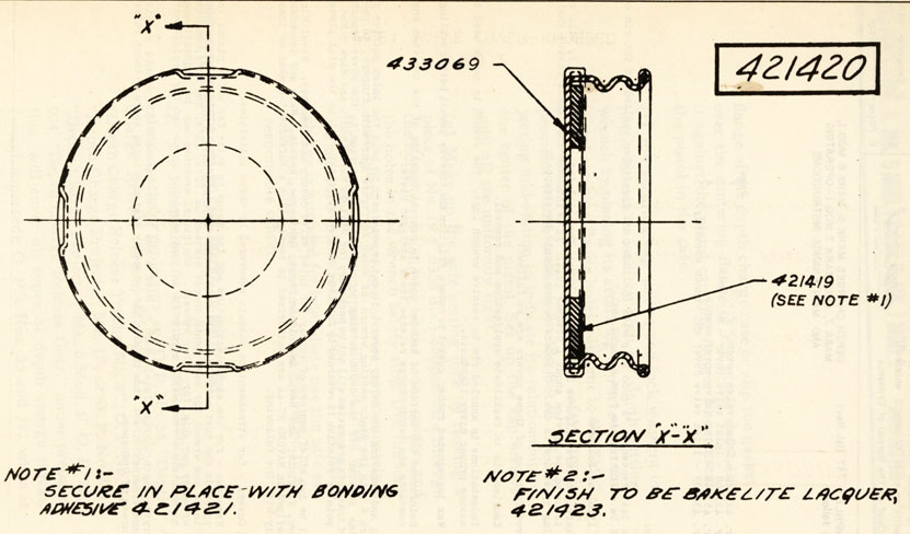
1 Dr. 421420 - Inlet valve cover - Plain
2
2 Dr. 433068 - Inlet valve cover - Knobbed
3
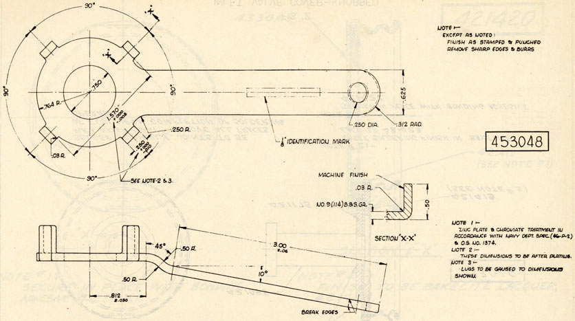
3 Dr. 453048 - Inlet valve cover wrench.
4
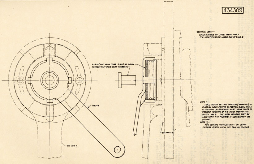
4 Dr. 434309 - Inlet valve cover and wrench assembly.
5
Page 97:
Paragraph 15:
Delete the last sentence, "A good grip with the thumb and forefinger applied at the rim of the cover will be sufficient to form a tight seal."
Add paragraph 15(a) as follows:
New type safety covers, figures 1 and 2, and wrench for applying same, figure 3, will be available for issue to the service about 1 October 1944. It is intended that these covers shall replace existing types now in use. Obsolete covers should be scrapped.
The improved features of these covers are as follows:
(a) Knurled rim to facilitate application and removal.
(b) Indentations in knurled rim to receive wrench lugs. The wrench is to be used to assure proper cover tightness.
(c) Wax impregnated rubber gasket to reduce friction and thereby permit better sealing.
(d) Reinforced top surface of knobbed cover to prevent buckling of the top when knob contacts the depth charge release track stripped plate.
When attaching and removing the safety covers, it may be necessary to hold the index pointer of the Pistol Mark 6 with the depth setting wrench as shown in figure 4,or with fingers, to pre vent moving the pointer off the depth setting by application of torque to the cover wrench.
It is believed that this precaution will not be necessary for Pistols Mark 6 Mod 1 and Mark 6 Mod 2 because index pointer rotation is retarded by friction of the watertight seal in the dial plate.
There will be two chief sources of supply for inlet valve covers and wrenches: Naval Mine Depot, Yorktown, Virginia; and Naval Ammunition Depot, Hawthorne, Nevada. Main and Secondary Stations as defined in NAVORD M7-44 are authorized to requisition a sufficient number of these items to comply with the following:
(a) Covers - for attachment to pistols recovered by these activities.
(b) Wrenches - for use at the activities and for issue to ships for which pistol inspection and test service is ordinarily rendered. The initial issue of wrenches to be one wrench for each depth charge station on DD's, DE's, and PF's; and two wrenches per ship for other vessels. Additional wrenches may be requisitioned to maintain a reasonable surplus for initial emergency issue and for replacement.
All ships carrying Depth Charge Pistols Mark 6, Mark 6 Mod 1, or Mark 6 Mod 2 should receive
valve covers and wrenches direct from the Main and Secondary Stations noted above without reference to the Bureau of Ordnance.
ch2-2
Fig 1
Inlet valve cover-plan. 421420
ch2-3
Fig 2
Inlet Valve Cover-Knobbed - 433068
ch2-4
Fig 3
Inlet Valve Cover Wrench - 453048
ch2-5
Fig 4
Inlet Valve Cover and Wrench Assembly- 434309
ch2-6
DISTRIBUTION
Requests for additional copies of OP 747, 1st Revision, Change 2 should be submitted on NAVORD FORM l, ORDNANCE PUBLICATIONS AND FORMS REQUISITION, to the nearest Ordnance Publications Distribution Center: Navy Yard, Wash. 25, D.C.; Adak, Alaska; Mare Island, Calif.; Pearl Harbor, T.H.; Espiritu Santo, New Hebrides; Exeter, England; Brisbane, Australia. Distribution Center mailing addresses should be obtained from List 10 nn of the Standard Navy Distribution List, or from the reverse side of NAV0RD FORM 1.
Standard Navy Distribution List No. 27
2 copies each unless otherwise noted
b, c, e, i-m, p, r, x, y, aa-ee, jj, kk, nn, uu, vv*, xx, yy, aaa, bbb.
4.
(5 copies) a.
5.
b*, e.
6.
a.
7.
e, f, h, i, x, ee.
7.
(5 copies) b, c, j, 1, p, s.
7.
(10 copies) a.
8.
a*, b, h*, i, j, n(SPECIAL LISTS A, G, H, K, P, R, AA, BB), v, cc.
10
. h-j, t, u, jj, qq. 10. p.0 copies s*.
10.
(25 copies nn.
11.
a(BuShips, CNO, ComdtMarCorps).
12.
a, b(Revision 1). 14. a, q.
* Applicable Addressees.
ch3-1
RESTRICTED
NAVY DEPARTMENT BUREAU OF ORDNANCE WASHINGTON 25, D. C.
To all holders of Ordnance Pamphlet 747 (1st Rev.) insert change; write on cover 'Change 3 inserted' Approved by The Chief of The Bureau of Ordnance
OP 747 Change 3
(1st Rev.)
6 December 1944
2 Pages - Page 1
ORDNANCE PAMPHLET 747 (1st Rev.) is changed as follows:
DEPTH CHARGES MARK 6, MARK 6, MOD. 1,
MARK 7 AND MARK 7 MOD. 1
OPERATING AND MAINTENANCE INSTRUCTION
ILLUSTRATIONS
Figure
Page
1 BuOrd Dr. 434329 - Depth Charge Booster Mark 6 Mod. 4 - General Arrangement
2
Page 68:
Add paragraph 48(a) as follows:
Depth Charge Booster Mark 6 Mod. 4, Figure 1, is a conventional booster unit of 'tin can' construction similar to Depth Charge Booster Mark 6 Mod. 2. The use of rivets instead of spot welding to attach the booster head socket provides a more reliable connection to withstand shipboard handling, shock and vibration. After loading and sealing the booster is coated with rust preventive compound (52-C-18) Grade 2 by spraying or dipping at the loading depot. This protective treatment should also be applied aboard ship from time to time as circumstances require to prevent corrosion of the can. The Booster Mark 6 Mod. 4 contains approximately 3.125 pounds of granular TNT. The total weight of the component is approximately 3.875 pounds.
DISTRIBUTION
Requests for additional copies of OP 747 First Revision Change 3 should be submitted on NAVORD FORM 1, ORDNANCE PUBLICATIONS AND FORMS REQUISITION, to the nearest Ordnance Publications Distribution Center: Navy Yard, Wash. 25, D.C.; Adak, Alaska; Mare Island, Calif.; Pearl Harbor, T.H.; Espiritu Santo, New Hebrides; Exeter, England; Manus Island, Admiralty Islands. Distribution Center mailing addresses should be obtained from List 10nn of the Standard Navy Distribution List, or from the reverse side of NAVORD FORM 1.
Standard Navy Distribution List No. 28
2 copies unless otherwise noted
b, c, e, i-m, p, r, x, y, aa-ee, jj, kk, nn, uu, vv*, xx, yy, aaa, bbb.
4.
(5 copies) a.
5.
b*, e.
6.
a.
7.
e, f, h, i, x, ee.
7.
(5 copies) b, c, d, j, 1, p, s.
7.
(10 copies) a.
8.
a*, b, h*, i, j, n(SPECIAL LISTS A, G, H, K, P, R, AA, BB), v, cc.
10.
h-j, t, u, jj, qq, ss.
10.
(10 copies) s*.
10.
(25 copies) nn.
11.
a(BuShips, CNO, ComdtMarCorps). 12, a, b(Revision 1).
13.
hh, nn.
14.
a, q.
* Applicable Addressees.
ch3-2
ch4-1
RESTRICTED
NAVY DEPARTMENT BUREAU OF ORDNANCE WASHINGTON 25, D. C.
To all holders of Ordnance Pamphlet 747 (1st Rev.) insert change; write on cover 'Change 4 inserted' Approved by The Chief of The Bureau of Ordnance
OP 747 Change 4
(1st Rev.)
25 July 1945
2 Pages - Page 1
ORDNANCE PAMPHLET 747 (1st Rev.) is changed as follows:
DEPTH CHARGES MARK 6, MARK 6, MOD. 1,
MARK 7 AND MARK 7 MOD. 1
ILLUSTRATIONS
Illustrations:
Page
Figure 1 - Bureau of Ordnance Dr. No. 389143.
2
Page 3. paragraph 2:
To superseded Ordnance Circular Letters, noted in first sentence add, "M23-43".
Page 68(c) Paragraph 12(c), (Change 1):
Change sentence, "The torque applied to assemble the mechanism should be not less than 60 ft./lbs. nor more than 75 ft./lbs.", to read, "The torque applied to assemble the mechanism should be not Less than 40 ft./lbs., nor more than 50 ft./lbs."
Page 90:
Add the following paragraphs after paragraph 3:
3(a) The modified depth setting wrench, figure 1, was approved by OCL No. M23-43, for use with Depth Charge Release Tracks Mark 4, Mark 5, and Mark 7. This modification of the standard depth setting wrench (Dwg. No. 180379-10) was required in order to eliminate interference between the handle of the standard type wrench and the track structure of these tracks, when making depth settings.
3(b) Aside from eliminating interference, the modified wrench has proved to be more convenient to handle and use than the standard type wrench, having particular application where depth settings must be made through hand holes in track structure. Such hand holes have recently been added by Ordalt No. 2238 to the next to aftermost posts of Depth Charge Release Tracks Mark 3, Mark 3 Mod 1, and Mark 6 to permit access for depth setting on pistols attached to the second after most depth charges in these tracks. Therefore, vessels having these tracks installed for service use, will find it advantageous to have the standard depth setting wrenches, issued to them with .the service tool sets, modified in accordance with figure 1.
3(c) The modifications required are such that vessels can readily modify the standard depth setting wrenches, or have the work performed by tenders, bases or Navy Yards. The Bureau of Ordnance will .not supply the modified depth setting wrench. Since the modification of the standard wrench, as noted herein, will eliminate the screw driver end, a separate tool will be required for making the deep settings on Pistols Mark 6 Mod 1 and Mark 6 Mod 2. In this respect the use of a medium size screw driver, as noted in Paragraph 3, will serve the purpose.
DISTRIBUTION
Requests for additional copies of OP 747 (1st Rev.) Ch. 4 should be submitted of NAVORD FORM l, ORDNANCE PUBLICATIONS AND FORMS REQUISITION, to the nearest Ordnance Publications Distribution Center: Navy Yard, Wash. 25, D. C.; Adak, Alaska; Mare Island, Calif.; Guam Island, Marianas; Pearl Harbor, T. H.; Manus Island, Admiralty Islands. Distribution Center mailing addresses should be obtained from List 10nn of the Standard Navy Distribution List, or from the reverse side of NAVORD FORM.l.
Standard Navy Distribution List No. 29 (C) and 32 (R) 2 copies unless otherwise noted.