1. Depth charge components are generally shipped separately. Manufacturing specifications require that each pistol and booster extender mechanism shall be packed in a separate corrugated paper carton and shipped in substantial wooden boxes, ten pistols or extender mechanisms to a box. Reshipment from depots is made in the original cartons and boxes when practicable. The flanged central tube openings of cases, both empty and loaded should be closed with gaskets and metal shipping covers when in storage or in transit. Detonators are packed six to a metal container. Two metal containers are enclosed in a wooden box. Loaded boosters are packed twenty-five to a wooden box for shipment.
70
DETONATOR STOWAGE BOX
END VIEW
DETONATOR STOWAGE BOX TOP VIEW
2. Pistol stowage box and booster stowage can are furnished for storage of the respective depth charge components aboard ship. When the pistol without detonator is stowed apart from other components, the index pointer should be set at the 30 foot position and the plain safety cap should be in place. When the booster and its extender mechanism are stowed apart from other components, the plain safety fork should be in place on the extender spindle. In general the storage of depth charges and their components afloat shall be in accordance with Bureau of Ordnance Manual, Chapter XIV, Paragraph 14C10 and Chapter XVIII, Paragraph 18C15.
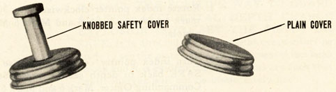
3. During shipment and stowage of a depth charge pistol, the inlet valve is closed by a plain shipping cover screwed onto the valve body. When a charge is
71
PISTOL STOWAGE BOX END VIEW
PISTOL STOWAGE BOX FRONT VIEW
placed in a depth charge track this cover is replaced with one fitted with a projecting knob. The knob is broken off the cover by a wiping plate on the track when the charge is dropped, leaving an opening through which water can enter the pistol. If a charge is thrown from a projector, the plain cover is used.
Before the projector is fired the plain cover must be removed by hand.
72
73
CAUTION
4. POSSIBLE DANGER TO PERSONNEL AND MATERIAL FROM DEPTH CHARGES ACCIDENTALLY RELEASED DUE TO THE EFFECTS OF ENEMY ACTION MUST BE EMPHASIZED. Damage to equipment or loss of life may occur if the ship sinks or if the depth charge launching gear, including tracks and projectors, are deformed or distorted in such a way as to permit depth charge not set on "safe" to drop overboard accidentally. Undamaged depth charges, Marks 6 and 7, may be prevented from detonating as a general rule ONLY by leaving safety forks in position or by setting the pistols on safe. It is felt, therefore, that by STRICTLY FOLLOWING THE PRECAUTIONS GIVEN HERE, casualties caused by a ship's own depth charges should be reduced to a minimum.
WHEN DEPTH CHARGES ARE READY
5. Conditions for readiness of depth charges, reported to be in use by U. S. destroyers, should be observed by all vessels carrying depth charges. These conditions are outlined as follows:
(a) Depth Charges in Depth Charge Tracks
(1) Depth charge assemblies are complete with pistols, detonators and booster extender installed.
(2) Knobbed safety covers are in place on pistol.
(3) Knobbed safety forks are in place on booster extender.
(4) Depth setting is set as prescribed by Commanding Officer.
For certain conditions which hinder normal operation of tracks, such as severe icing or damage to track release mechanisms, any change from regular procedure is left to the discretion of the commanding officer. Under normal conditions the knobbed safety
74
75
forks and covers must be stripped by the wiping plate only and should not be connected to the racks, or other nearby structures.
(b) Depth Charges in Y-Guns or Projectors
(1) Depth charge assemblies are complete with pistols, detonators, and booster extender installed.
(2) Inlet valve cover is removed (only for immediate firing.)
(3) Plain safety forks are in place on booster extender, with one foot chain or manila lanyard attached for removal by hand. Lanyard is attached only to safety fork.
(4) Depth charge is fastened firmly in arbor by the arbor chain and marline or spun yarn lashing. Lashing need not be used if depth charge projector has just been loaded for immediate firing.
(5) Depth setting is prescribed by commanding officer.
CAUTION
6. The chain lanyard originally used with the Mark 6 single projector for automatic safety fork removal is no longer advocated. Not only should this procedure be discontinued in connection with Mark 6, but also with Mark 1 (Y-Gun) projector in order to avoid in all cases a condition where the forces of wind, sleet, waves, or deformations of structure to which the chain lanyard is attached may cause the removal of the safety fork.
7. Since the safety forks may be knocked off by explosions or flying material, compliance with the instructions listed in paragraph 5 will not give complete assurance that the depth charges will not
76
explode if accidentally dropped overboard. But such compliance will aid in maintaining a greater percentage of the safety forks in place. With the safety fork fixed on the booster extender it is impossible for
the booster to arm. And in the event that the pistol fires the detonator, explosion of the main charge will not result. THE POSITIVE WAY TO GUARD AGAINST ACCIDENTAL DEPTH CHARGE EXPLOSION IS TO SET THE PISTOL ON SAFE. It is directed, therefore, that every effort be made to set the pistols on safe if the vessel has been struck and it is evident that conditions are such that depth charges will not be immediately used.
DEPTH CHARGE UPKEEP ROUTINE FOR SHIPS
8. The following routine is recommended for the
depth charge components noted when carried in release tracks, roller loaders, projectors or in stowage racks on decks of ships:
77
(a) DAILY ROUTINE FOR PISTOLS in ready condition and safe setting lock not attached.
1. Rotate index pointer clockwise from 30 foot mark to SAFE. Mark 6 and Mark 6 Mod. "1 pistols.
2. Turn index pointer counter clockwise from SAFE back to depth setting prescribed by Commanding Officer. Mark 6 and Mark 6 Mod. 1 pistols.
3. Remove safety cover and rotate index pointer of deep firing mechanism clockwise from "0300" to "600." Mark 6 Mod. 1 pistol.
78
4. Turn index pointer of deep firing mechanism counter clockwise from 600 back to depth setting prescribed by Commanding Officer and replace safety cover. Make sure cover is screwed on tightly.
5. Examine safety covers. If any are defective in slightest respect, replace them. Make sure that covers are screwed on tightly. Mark 6 and Mark 6 Mod. 1 pistol.
79
WEEKLY ROUTINE FOR PISTOLS
(b) WEEKLY ROUTINE FOR PISTOLS in release tracks, roller loaders, arbors on projectors and stowage racks on deck, with safe setting lock
attached:
1. Apply a few drops of light oil (#2110) on surface between index pointer and dial plate and around index pointer plunger. Rotate index pointer counter-clockwise from safe to 30 foot mark. Safe setting lock will be broken by this operation. Mark 6 and Mark 6 Mod. 1 pistol.
2. Turn index pointer clockwise back to SAFE. Install safe setting lock. Mark 6 and Mark 6 Mod. 1 pistols.
3. Remove safety cover and rotate index pointer of deep firing mechanism counter-clockwise from "500" to "0-300." Mark 6 Mod. 1 pistol.
4. Turn index pointer of deep firing mechanism clockwise from "0-300" back to "500" and replace safety cover. Make sure cover is screwed on tightly.
5. Examine safety covers. If any are defective replace them. Make sure that covers are screwed on tightly. Mark 6 and Mark 6 Mod. 1 pistol.
CAUTION: Do not attempt to rotate index pointer clockwise from SAFE to 30 foot mark or counterclockwise from 30 foot mark to SAFE. This may shear off index pointer stop pin. Mark 6 and Mark 6 Mod. 1 pistols.
80
(c) DAILY ROUTINE FOR BOOSTER EXTENDER MECHANISM in release tracks, roller loaders, arbors on projectors and stowage racks on deck:
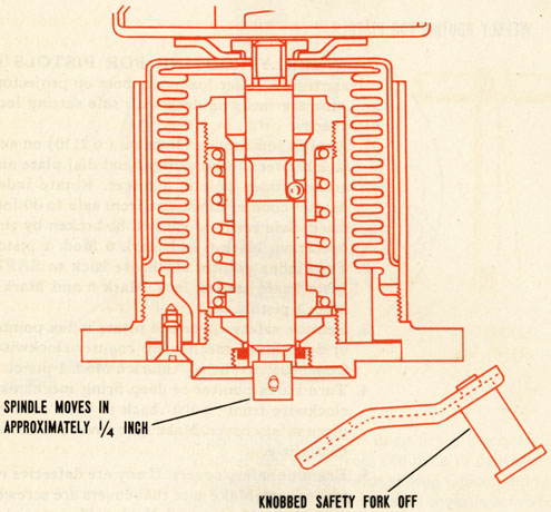
1. Remove safety fork and note that spindle moves in approximately 1/4 inch when the fork is pulled off. Mark 6 and Mark 6 Mod. 1 extenders.
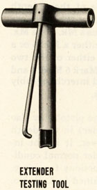
2. Attach extender testing tool to extender spindle by placing recess, in end of tool, over the outboard end of spindle. Mark 6 and Mark 6 Mod. 1 extenders.
81
3. Using a medium pressure, work extender spindle in and out 10 times. Spindle travel must not exceed 3/4 inch. Any further inward travel of spindle places booster envelope over the detonator and is dangerous. If spindle does not operate with reasonable freedom the booster extender should be removed from the depth charge and turned in for overhaul. The foregoing applies to both the Mark 6 and Mark 6 Mod. 1 booster extender mechanisms. If spindle sticks in seal on Mark 6 Mod. 1 booster extender when fork is removed back off on gland screw about 1/4 turn with gland wrench. The function of the gland seal is to prevent moisture entering the booster extender hydrostatic chamber when the safety fork is in place on the spindle. Excessive slackening of the packing gland will permit water to leak along the spindle into the booster extender chamber, with resultant corrosion and, at times, freezing around internal operating parts. Make sure that the testing tool is properly centered on the spindle so that the gland seal will not be damaged when the edge of the tool passes through it as the spindle is pushed in.
4. Remove the extender testing tool.
5. Replace the safety fork. Bent or otherwise deformed safety forks must be replaced.
82
INTERCHANGEABILITY OF PARTS
9. To simplify assembly and use of these depth charges, all of the components except the cases are designed to be interchangeable. Thus a Mk. 6 or a Mk. 6 Mod. 1 pistol may be used with either a Mk. 6 or a Mk. 6 Mod. 1 booster-extender in either of the two cases, Mk. 6 or Mk. 7. Also Mark 6, Mark 6 Mod. 1 and Mk. 6 Mod. 2 boosters may be used interchangeably with pistols and booster-extenders.
10. The Mk. 7 Mod. 1 depth charge pistol may also be used (without a booster-extender) in the depth charge cases listed above. However, it is not intended that this shall be done under normal conditions. A description of, and instructions for using, the Mk. 7 Mod. 1 pistol, are contained in O.P. No. 866, (First Revision).
83
ICING
O.P. NO. 747
MARK 6 PISTOL AND BOOSTER EXTENDER MECHANISM
11. To avoid freezing of the internal operating parts, an anti-freeze mixture of 2/3 glycerine and 1/3 alcohol is recommended for use in both the booster and pistol ends. Both of these constituents possess anti-freeze properties. Furthermore the increase in viscosity of the glycerine at low temperatures is such that it aids in the retention of the mixture within the booster extender in the absence of a sealing substance, and at the same time does not become stiff enough to interfere with proper operation. At low temperatures, in the range of 0° F. to 20° F., and without any retaining grease or putty, the leakage of antifreeze around the booster spindle has been found to be negligible for a period in excess of 24 hours.
12. In case of the unavailability of the mixture mentioned in paragraph 11, other non-corrosive antifreeze combinations may be used but these have certain limitations. For example, a 70% glycerine-30% water mixture possesses a good anti-freeze qualities but will have a higher freezing point than the glycerine-alcohol combination with the same amount of sea water dilution. Alcohol, if used separately, runs out of the booster extender quite readily, and it is advisable, therefore, to use a sealing substance applied around the safety fork and booster spindle. Kerosene is not too satisfactory since it not only runs out too readily without a retainer but also reduces appreciably the effectiveness of practical sealing substances such as putty or plastilene.
13. Possible methods of introducing anti-freeze mixtures into the booster extender and pistol are suggested as follows provide the pistol and booster
84
extender are removed from the depth charge or the depth charge turned up on the appropriate end:
(a) For the booster extender, the safety fork should be removed and anti-freeze should be poured into the clearance between the booster spindle and the spindle bushing by means of a funnel, trough, or oil can. If difficulty is encountered using this method, an alternate method is suggested in which a screw driver or other suitable rod may be used on the booster spindle end, with the safety fork removed to force the end into a position about 1/16 inch inside the outer surface of the spindle bushing. The anti-freeze may then be poured by means of a funnel into the spindle bushing opening and will filter by the spindle end into the booster bellows chamber. Caution must be taken not to push the spindle end farther down the spindle bushing opening than 1/16 inch. If such a precaution is not observed, the locking balls will slip out of position in the locking slide and prevent the spindle's return to the normal unarmed position without use of a special tool.
(b) For the pistol, alternate methods may be employed. An oil can may be used to squirt the antifreeze into the 1/8 inch inlet valve holes or through the orifice in the valve seat head. A service pistol cover, with the knob removed, may be successively screwed on each pistol and used as a funnel, the anti-freeze being poured into the cover hole.
85
14. Tests have indicated that serious sticking of the booster extender mechanism at low temperatures is mainly due to the effect of frost or ice around the locking balls of the booster release mechanism rather than to the results of water freezing in the bellows. Jamming is also known to occur at low temperatures in seemingly dry boosters because of the condensation and freezing of water vapor from the air within the extender. It is evident therefore that an antifreeze solution is necessary even in the event that a waterproof seal is used. It is recommended that 2 or 3 ounces of anti-freeze be poured into the booster spindle opening. This should be sufficient to furnish an initial coating of all the working parts and provide a reservoir for subsequent coatings and for dilution of any water that may enter.
15. Laboratory tests indicate that putty may be used as a sealing substance for the booster end. Putty sticks to the metal readily and breaks off cleanly on removal of the safety fork. Plastilene also possesses sealing properties comparable to putty but is not as easy to apply. If difficulty is experienced in causing the sealing substance to cling to the metal, a retainer
86
of adhesive tape ("Scotch" tape, for example is recommended. The use of a seal such as putty when the viscous glycerine-alcohol mixture is employed in the booster, while possibly not necessary at extremely low temperatures, is advisable as an added assurance against seepage of water into, or anti-freeze out of the booster extender. With the less viscous liquids mentioned in paragraph 12, it is considered essential that a sealing substance be used to avoid the necessity for frequently replenishing the anti-freeze.
16. The use of wax or grease, including gun slushing compounds and ice machine grease, as a seal is not recommended because of the tendency to prevent water inflow under depth-charge operating conditions. Furthermore, these substances should especially not be used inside either pistol or booster extender because of their tendency to cause sluggish action.
17. It is suggested that the safety forks on the depth charges in position on the racks be rotated so that the knobbed end of the fork is up. This procedure avoids the funnel effect that the prong end of the fork, in upward position, offers to the spray.
87
Recent laboratory tests have shown that the dry pistol, unlike the booster extender will not fail to operate due to the formation of frost. Also, the locking ball mechanism which would be expected to cause jamming on freezing is located in a position to which water is not readily admitted. However, water is frequently known to enter the pistol around the inlet valve cover and quite conceivable may freeze in the inlet valve. It is therefore considered desirable to flush the pistol end with anti-freeze through the inlet valve or through the orifice in the valve seat head. It must be emphasized that this flushing ing pin release mechanism. It is possible that the flooding of this unit will cause a dashpot effect that will retard the firing pin motion. Proper coating of parts with polar type rust preventive compound is considered sufficient protection of this mechanism against any possible freezing or corrosion.
18. It is understood that inlet valve covers are frequently broken in handling and that occasionally they leak. Naturally, these should be replaced at once if broken. Although the design of these covers has been strengthened, regular inspections of covers for leakage should not be relaxed.
20. Both in connection with difficulties from icing and difficulties from corrosion it is considered desirable, after a ship returns to port, generally to replace firing mechanisms immediately with spares and to clean and recondition the old ones so that they can be turned in to the pool of spares for this purpose. To facilitate this policy a more liberal supply of spares is being obtained. Replacement on shipboard of firing mechanisms which seem probably in doubtful condition after rough or icy weather seems also desirable.
88
21. The use of anti-freeze within the depth charge operating mechanisms does not assure by itself proper functioning of the depth charge. Ice on the exterior of the ends of the depth charge is likely to cause malfunctioning of both booster and pistol. The safety fork on the booster end generally will not wipe off if completely iced over, and it is possible that the knobbed cover on the pistol end will not break off cleanly. To date, ice removal has been accomplished by means of steam and hot water flushing. Tests have proved the latter to be the more successful method and steps are being taken to supply all ships concerned with the necessary equipment.
22. Tests by the fleet under actual operating conditions have indicated the uncertainty of safety fork removal by the wiping plate even when the booster end has seemingly been deiced by steam hose. The requirement that the safety fork should be removed automatically by the wiping plate may be relaxed within the discretion of the Commanding Officer of each ship, with due regard for the added danger connected with the sinking of the ship or the accidental loss of a depth charge overboard.
23. Depth charges should, of course, not be expended without good reason. However, in order to determine the effectiveness of these instructions it would seem justified, and it is recommended when circumstances make it desirable that destroyers before returning to port occasionally drop one or two depth charges under freezing conditions to test the efficiency of these measures.


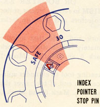 CAUTION: Do not attempt to rotate index pointer clockwise from SAFE to 30 foot mark or counterclockwise from 30 foot mark to SAFE. This may shear off index pointer stop pin. Mark 6 and Mark 6 Mod. 1 pistols.
 3. Using a medium pressure, work extender spindle in and out 10 times. Spindle travel must not exceed 3/4 inch. Any further inward travel of spindle places booster envelope over the detonator and is dangerous. If spindle does not operate with reasonable freedom the booster extender should be removed from the depth charge and turned in for overhaul. The foregoing applies to both the Mark 6 and Mark 6 Mod. 1 booster extender mechanisms. If spindle sticks in seal on Mark 6 Mod. 1 booster extender when fork is removed back off on gland screw about 1/4 turn with gland wrench. The function of the gland seal is to prevent moisture entering the booster extender hydrostatic chamber when the safety fork is in place on the spindle. Excessive slackening of the packing gland will permit water to leak along the spindle into the booster extender chamber, with resultant corrosion and, at times, freezing around internal operating parts. Make sure that the testing tool is properly centered on the spindle so that the gland seal will not be damaged when the edge of the tool passes through it as the spindle is pushed in.