44
|
|
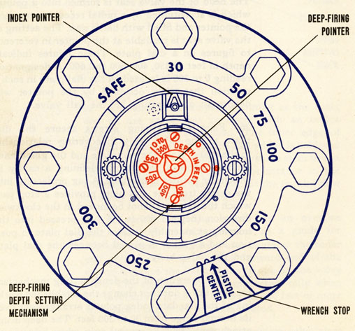
SAFETY WRENCH STOP
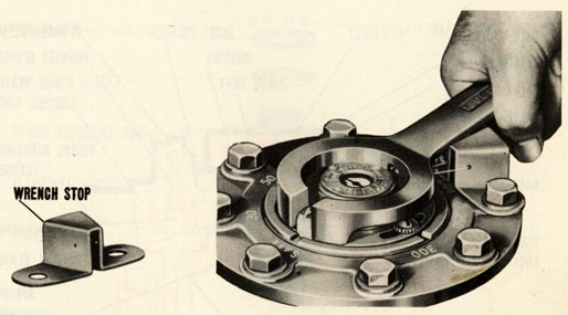
As an added feature to insure proper depth setting, a wrench stop, for depth setting wrench, is attached to the pistol carrying flange by two of the eight standard case cap screws and lock washers which secure the pistol in the depth charge case. The correct location of this wrench stop is obtained by placing its attaching cap screws in the pistol carrying flange holes adjacent to the "150" and "250" dial marks.
Premature or inaccurate firing of a pistol may also be caused by improper assembly or corrosion of parts. To insure proper operations, the instructions in Chapters V and VI for testing, repairing and overhauling pistols must be followed closely.
|
45
|
|
SAFE SETTING LOCK
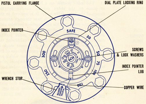
19. A SAFE SETTING LOCK prevents the shock of gunfire, bomb hits or underwater explosions from moving the index pointer off the SAFE setting. This lock consists of a short piece of No. 19 (".0358 dia.) copper wire rove through holes in lug of index pointer and wrench stop. The ends of the wire are twisted together. The index pointer is thereby secured in the SAFE position and cannot be moved until wire is broken. Round nose pliers, furnished in service tool sets, are used to install the wire. It is not necessary to remove the locking wire to change the index pointer from SAFE to a particular depth setting. The wire will be broken by the application of force to depth setting wrench handle. Whenever index pointer is reset to SAFE a new piece of wire is required. Wire, wound on spool for convenient use, is included in service tool set. Modification of pistols in service and in store to add this feature is covered by Ordalt No. 1735.
|
46
|
|
MARK 6 MOD, 1 PISTOL
20. The Mark 6 Mod. 1 pistol differs from the Mk. 6 pistol in that a spring-loaded depth-controlling valve for deep-firing is installed in place of the inlet valve assembly of the original design.
DEPTH SETTING MECHANISM - FOR DEEP FIRING
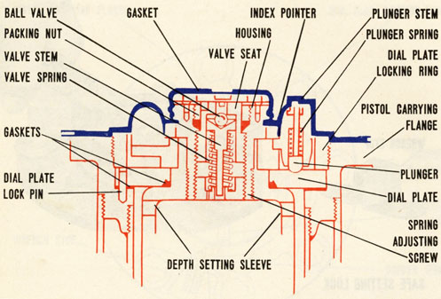
21. The depth setting mechanism for deep firing (depth controlling valve) consists of a valve body the exterior of which is identical with the inlet valve body of the Mark 6 pistol. The valve
|
47
|
|
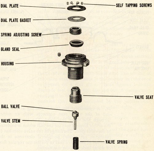
body has bores of different diameters from the respective inner and outer ends. The bore from the inner end is fully threaded. The bore from the outer end is threaded only part way. It supports a gland which compresses a packing against the sloping wall of an annular shoulder. This shoulder separates the bores and provides a stop against which the shoulder of an externally threaded portion of a valve seat is initially driven.
|
48
|
|
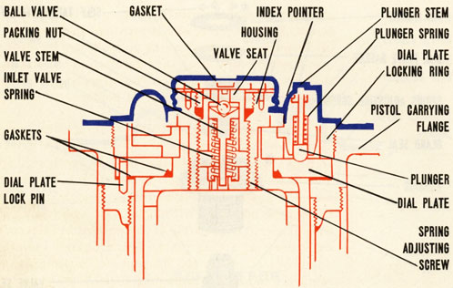
22. A cylindrical chamber beginning at the inner end of the valve seat connects with an orifice through the valve seat head. The inner edge of the orifice forms a seat for the ball which is soldered to the valve stem. The flange of the valve stem has (a restricted yet ample) peripheral clearance in the chamber of the valve seat to permit the regular flow of water back into the mechanism.
23. A spring adjusting screw has an oversize hole, the wall of which serves as a guide for the valve stem. This screw also contacts the inner end of the valve spring. The forward end of the spring engages the back of the flange on the valve stem. The spring is under compression only when the mechanism is set for depths of 350 feet or more whereupon the valve becomes seated.
24. Water flows through the oversize valve stem hole in the spring adjusting screw and also

|
49
|
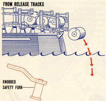
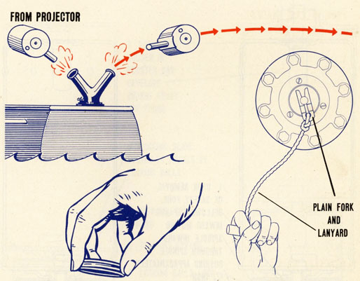
|
through a supplementary hole in this adjusting screw. A screw driver slot is provided in the adjusting "screw for adjusting spring compression by means of a screw driver during the operation of calibrating the valve. After calibration the adjusting screw is locked in place with a spot of solder.
25. The head of the valve seat is also provided with a screw driver slot for screw driver setting of this member to the required depth setting. The head of the valve seat is formed into a pointer which is accentuated by a radial recess centered on the pointer and filled with black wax. The setting of the valve seat is readable at the pointer in reference to figures on a dial plate. These figures indicate depth in feet of 350, 400, 500 and 600. A designation reading 0 to 300 is located on the dial plate in such a position that when occupied by the pointer will denote an open setting for the ball valve.
26. Four self tapping screws secure the dial plate to the valve body in covering relationship to the gland. Both the dial plate and the gland have central openings collectively defining a cavity in which the pointer is movable. A lug projecting into the cavity from the dial plate provides a stop past which the pointer cannot be moved in the clockwise direction (beyond 600 ft.) A pin, pressed into the housing at assembly, locates the dial plate in position and a gasket is placed between the dial plate and the valve body.
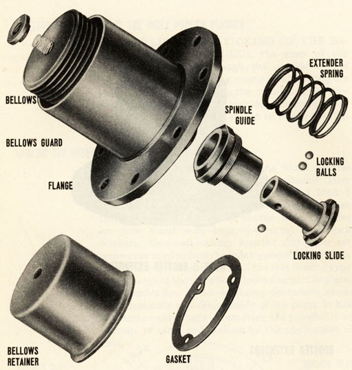
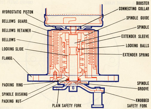
27. The operation of the depth setting mechanism for deep firing does not change the established working of the standard index pointer arrangement over its normal range from 30 to 300 feet. The deep firing attachment assumes control only when firing is to be accomplished in excess of 300 feet.
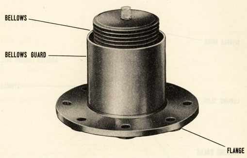
|
50
|
|
DEEP FIRING ATTACHMENT
28. The deep firing attachment lacks the anti-countermine device of the inlet valve which it replaces. However, it is believed that anti-countermining depends upon high surge impedance of the small liquid passageways rather than the inward closing of an anti-countermining valve. Therefore, the close clearances around the valve stem flange and valve stem are relied upon to prevent countermining.
|
51
|
|
MAKING A DEPTH SETTING
29. When it is desired to make a pistol depth setting in excess of 300 feet the large index pointer is set to 100 foot mark. Then the safety cover is removed and the setting on the deep firing attachment is made at any indexed position by less than a full clockwise turn of a screw driver inserted in the slot of the valve seat. The safety cover is replaced after the setting. The effect of turning the valve seat is to screw it away from the shoulder in the valve body The seat thus catches up with the valve and closes the orifice. Since the adjusting screw is fixed the heretofore slack spring is put under compression in amounts proportional to the depth setting.
30. Upon knocking off the knob prior to dropping the depth charge overboard, water will enter the resulting hole in the cover. A hydrostatic pressure coinciding with the depth of submergence and the index depth setting of the pointer will unseat the ball valve against the compression of the spring and water will flow into the pistol hydrostatic chamber to operate the pistol in the manner previously described.
31. Gaskets are installed between the dial plate the depth-setting sleeve and the flange of the Mk. 6 Mod. 1 pistol so that it may be used in depths of 350 to 600 feet without leakage into the pistol to cause premature firing. The exterior thread of the deep-firing mechanism valve body is coated with thread compound at assembly to insure water tightness at this joint.
|
52
|
|
TO ELIMINATE STICKING OF THE INDEX POINTER PLUNGER
32. TO ELIMINATE STICKING OF THE INDEX POINTER PLUNGER, the stem of the plunger is extended through the outside of the pointer boss. This provides a means of lubricating the stem without disassembling the pistol, and the protruding portion of the stem provides a means of moving the plunger within its socket to free it if it becomes stuck.
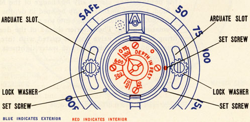
LOCKING SET SCREWS
33. The use of solder for locking index pointer screws and valve body was discontinued after production got under way on the Mark 6 Mod. 1 pistol. The round head brass screws which pass through the arcuate slots of the index pointer are now fitted with internal-external type lock washers. Two self-locking knurled cup point set screws are used to lock the index pointer to the index pointer carrier. One set screw of the self-locking type in the flange of the valve body locks this part in place. The elimination of the soldering operations expedites assembly and disassembly of the parts. It has the further advantage of removing the possibility of damage to seals and gaskets by the application of heat.
|
53
|
|
MARK 6 BOOSTER EXTENDER
BOOSTER EXTENDERS
34. BOOSTER-EXTENDERS are hydrostatically-operated devices which hold the booster charges away from the detonators until after the depth charges are submerged. When a booster-extender installed in a depth charge is in the safe position, the distance between the detonator and the booster charge is such that even if the detonator should explode accidentally, the booster and main explosive charges would not be detonated. When a booster-extender
|
54
|
|
|
55
|
|
BOOSTER EXTENDERS
|
O.P. NO. 747 |
PARTS
operates it moves the booster charge toward the pistol until the detonator is housed in an envelope in the end of the booster can. The end of the booster can then rests against the centering flange on the inner end of the pistol. These mechanisms are designed to operate without adjustment at depths of 11 to 22 feet.
|
56
|
|
HOW THEY WORK
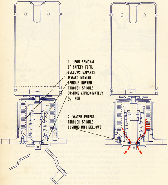
35. When a depth charge is dropped from a release track, the knobbed safety fork on the booster-extender is stripped from the mechanism by a wiping plate on the track. If a charge is thrown from a projector, the plain safety fork is removed from the mechanism by hand before the projector is fired.
36. When the fork is pulled off the spindle, the bellows expands inward approximately 1/4-inch, moving the spindle inward through the spindle bushing. This carries the reduced diameter of the outer portion of the spindle into the opening in the bushing so that there is space around the spindle through which water can enter the bellows. The spindle groove in which the locking balls rest is slightly elongated to provide for this initial motion of the spindle.
|
57
|
|
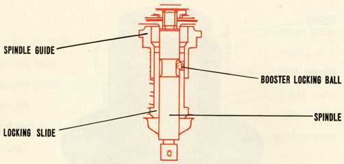
37. As water enters the bellows it forces the piston and spindle inward. Since the locking slide is locked to the spindle by the locking balls, the slide is carried inward with the spindle against the pressure of the extender spring. When the spindle moves far enough inward to carry the locking balls into the enlarged section of the spindle guide, the balls slip outward into the guide, freeing the spindle from the locking slide.
38. The only resistance to further inward motion of the piston is provided by the bellows. Since this is comparatively light, hydrostatic pressure now drives the piston inward until it carries the booster can against the centering flange on the depth charge pistol. At this point the detonator is housed in the envelope in the end of the booster can.
|
58
|
|
|
59
|
|
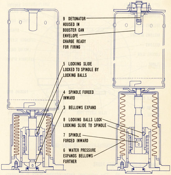
Drawings showing bellows expanding until detonator charge ready for firing.
|
60
|
|
MARK 6 BOOSTER-EXTENDER PARTS
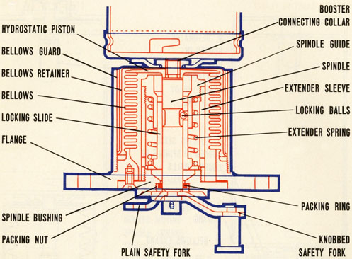
39. The principal parts of the Mark 6 booster-extender are:
a flange with which the mechanism is secured in the central tube of a depth charge case
a metal bellows which forms an expansive watertight container for the operating parts of the booster-extender
a bellows guard to protect the bellows

|
61
|
|
GENERAL ARRANGEMENT
a piston
a spindle and spindle guide
a locking slide.
Since this mechanism may be used with a Mark 6 Mod. 1 pistol the original design has been modified to include a bellows retainer. Any mechanisms not so equipped should be modified in accordance with Ordalt No. 1505.
|
62
|
|
THE BELLOWS
40. The outer end of the bellows secured to the inner side of the flange, while the piston is fastened to the inner end of the bellows. A cupped shaped retainer is placed over the piston and bellows. A collar for attaching a booster can to the mechanism is mounted on the inner end of the mechanism and secures the bellows retainer in place.
THE SPINDLE
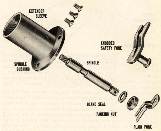
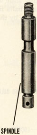
41. The spindle, which extends outward through a bushing in the center of the flange when the mechanism is in the unoperated position, is secured to the inner surface of the piston. An extender sleeve is

|
63
|
|
 secured to the inner side of the spindle bushing, and the spindle guide is mounted inside the inner end of the sleeve. The locking slide is installed between the spindle guide and the spindle, and an extender spring is placed between the spindle guide and the locking slide. This spring and the normal tension of the bellows hold the mechanism in the unoperated position until hydrostatic pressure is applied to it.
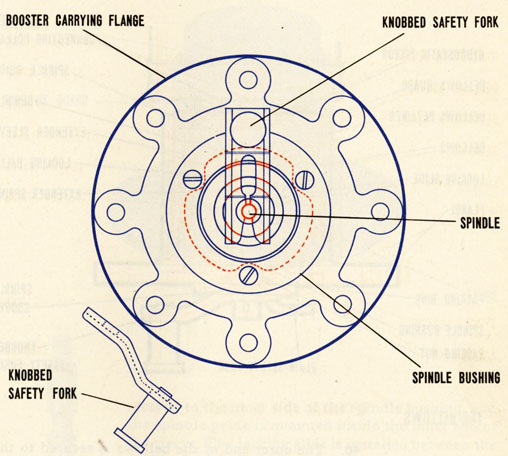
42. The outer end of the spindle, which projects through the spindle bushing is grooved to take the safety fork which locks the mechanism safe prior to use. A plain fork is used during shipment and storage and when the charge is fired from projectors. This is replaced by a knobbed fork when a depth charge is placed in a release track.
|
64
|
|
LOCKING BALLS
43. Locking balls are fitted in the locking slide of the mechanism. In the safe position these balls fit in a groove in the spindle and are held there by the spindle guide.
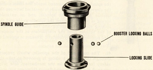
LOCKING BALLS AND LOCKING SLIDE
|
65
|
|
MARK 6 MOD. 1.
|
O.P. NO. 747 |
BOOSTER EXTENDER
MARK 6 MOD, 1 BOOSTER-EXTENDER
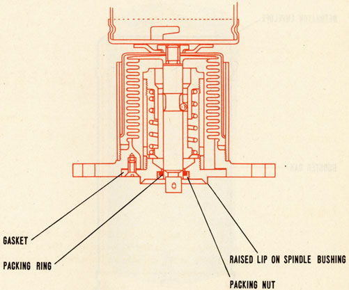
44. The Mk. 6 Mod. 1 booster-extender differs from the Mk. 6 in that it has a packing ring, a locking ring, and a raised lip on the spindle bushing, and a gasket between the bushing and the booster carrying flange. The packing ring and the gasket are designed to prevent moisture from entering the mechanism prior to use and causing corrosion which might result in faulty operation. The lip on the bushing is designed to raise the shank of the safety fork slightly when it is installed or removed, thus moving the spindle along its own axis and freeing it if it is stuck to the packing ring or other parts of the mechanism.
|
66
|
|
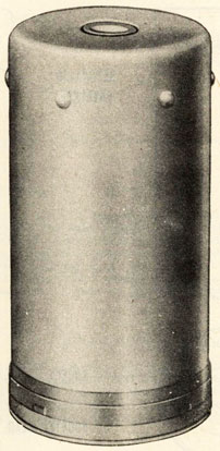
MARK 6 BOOSTER
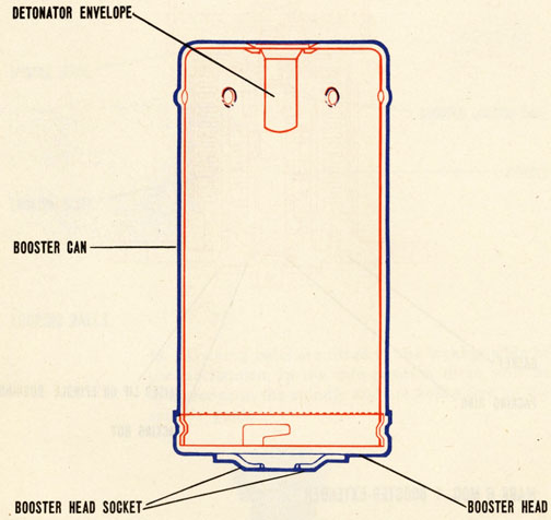
45. The Mk. 6 booster contains approximately 3.52 pounds of granular TNT. The booster can is made up of four parts:
the can itself
the detonator envelope
the head
and the socket (which fits the flanged collar on the booster-extender). All parts of this can are made of brass except the detonator envelope which is copper.

|
67
|
After the can is loaded, the head is locked in place by four lugs which engage slots in the can. The joint between the can and head is then secured with low-melting-point solder
MARK 6 MOD. 1 BOOSTER
42. The Mark 6 Mod. 1 booster is identical with the Mark 6 booster except that steel has been used as a substitute for brass material. The can is painted with a projective cavity paint on interior surfaces and zinc chromate primer on exterior surfaces.
|
68
|
|
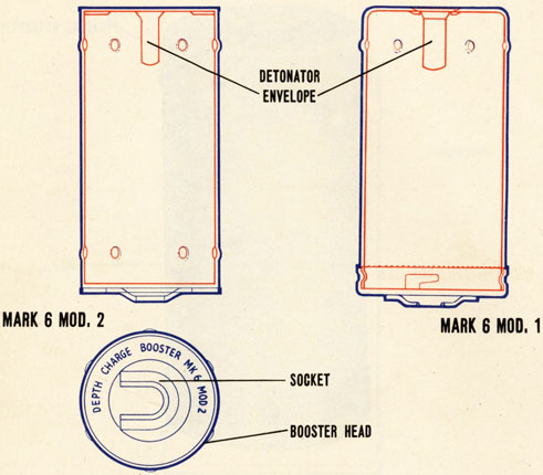
MARK 6 MOD. 2 BOOSTER
48. The Mark 6 Mod. 2 booster can is designed for production by commercial can manufacturers. After loading it is sealed by a standard can closing machine. The Mark 6 Mod. 2 booster contains approximately 3.12 pounds of granular TNT. In other respects the Mark 6 Mod. 2 booster is the same as the Mark 6 booster.
MARK 1 MOD. 1 DETONATOR
49. The Mk. 1 Mod. 1 percussion detonators provided for use in these depth charges are of the instantaneous type. Each detonator contains 65 grains of fulminate of mercury.

See Changes 1, at end of book.
See Changes 3, at end of book.
See Changes 4, at end of book.
|
