|
PART II
DESCRIPTION
201. GENERAL
|
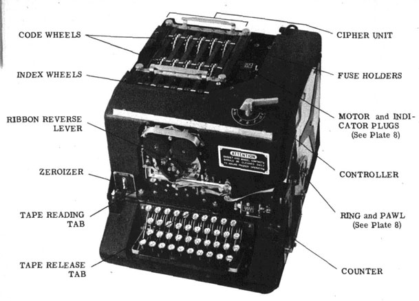
(a) The ECM Mark 2 is an electrically operated ciphering typewriter, assembled as one unit. The machine includes the following parts or features:
(1) Code Wheels and Index Wheels
(2) Cipher Unit
(3) Code Wheel Stepping Assembly
(4) Keyboard
(5) Printer
(6) Zeroizer
(7) Controller
(8) Electric Motor
(9) Main-shaft
(10) Emergency Hand Drive Lever
(11) Automatic Word Spacer
(12) Counter
(13) Spark Suppressors
(14) Input and Output Receptacles
|
202. CODE WHEELS AND INDEX WHEELS.
(a) Each Code Wheel consists of a steel ratchet, two face-plates and the wiring which connects the contacts of one face-plate to the contacts of the other face-plate.
|
(1) The 26 divisions of the steel ratchet serve a dual purpose - as a ratchet which the stepping pawl engages when the Code Wheel is stepped by the machine and as a detent for the detent rollers which hold the Code Wheel in definite positions.
(2) Each face-plate contains 26 contacts. One of the face-plates has the letters of the alphabet engraved on its periphery for reference purposes in making Code Wheel Alignments. The other face-plate is engraved with the identifying number of the Code Wheel. Each face-plate has a projection (between "U" and "V" of the engraved face) called the cam-lobe. The cam-lobe stops the Code Wheel at "O" when zeroizing and controls the stepping of the Code Wheels of the Stepping Maze. (See paragraph 203(d)(2).)
NOTE: Certain Code Wheels designed for use with Adapters to be used in the ECM Mark 2 contain cam-contours (See paragraph 602) on the periphery of each face-plate. Technically, these may be called "detents" , but since a division of the steel ratchet is called a "detent", the designation "cam-contours" is used to differentiate between the two.
(b) The Index Wheels are similar to the Code Wheels but are smaller, containing ten contacts. An Index Wheel has no steel ratchet because it Is not stepped by the machine; all setting must be done by hand. The Index Wheels are part of the Cipher Unit.
|
|
| |
-16-
|
|
203. CIPHER UNIT (CSP 887)
(a) The ciphering action of the ECM Mark 2 is produced by constantly interchanging the 26 alphabet circuits from the Keyboard to the Printer. When set for typing plain language, the machine is essentially an electric typewriter and will print the plain equivalent of the Keylever pressed because the circuits from the Keyboard are directly connected to the Printer. If, however, these circuits are interchanged or scrambled, the result will be a ciphering action. If the interchanged circuits are changed for each letter ciphered, the result will be a complex ciphering action. It is a function of the Code Wheels in the Alphabet Maze to produce the interchange of circuits, and the stepping of the Code Wheels constantly changes the ciphering action. When ciphering, the circuits from the Keyboard are connected through the Alphabet Maze Code Wheel circuits to the Printer.
(b) The Cipher Unit (CSP 887) is composed of six separators with through-contacts, detent rollers, spindles and Index Wheels. Two handles are provided to facilitate handling and four thumb-screws are provided for securing the Cipher Unit in place.
|
(1) The Cipher Unit contains, when the Code Wheels are inserted, all of the variable elements of the ciphering action. The removable feature of the Cipher Unit:
(A) Permits safe stowage of the cryptographic elements.
(B) Facilitates changing from one system to another when two Cipher Units are available.
(C) Facilitates emergency disposition overboard of the cryptographic elements.
NOTE: The ECM Mark 2, exclusive of the Code Wheels is classified CONFIDENTIAL. The Code Wheels are classified SECRET.
|
(c) The rear row of five Code Wheels and 26 associated circuits is called the ALPHABET MAZE. The 26 circuits from the Keyboard are connected through the Alphabet Maze to the Printer, but only one of the circuits is energized at a time. The function of the Alphabet Maze is to produce the ciphering action, which depends upon the arrangement and relative positions of the Code Wheels in the Alphabet Maze. During encipherment or decipherment, all five Code Wheels of the Alphabet Maze step in an erratic manner, in a ciphering cycle of substantially infinite length. IF, BECAUSE OF A FAILURE OF THE STEPPING CONTROL, THE CODE WHEELS DO NOT STEP, A SIMPLE SUBSTITUTION CIPHER RESULTS. (SEE PARA 203(f)).
(d)
|
(1) The front row of five Code Wheels (not the Index Wheels) and 26 associated circuits is called the STEPPING MAZE. Of the twenty-six circuits established only four are energized. The function of the Stepping Maze is to control in an irregular and erratic manner, the stepping of the Code Wheels in the Alphabet Maze.
(2) The automatic stepping of the Code Wheels in the Stepping Maze is controlled by the cam-lobes of the Code Wheels and the Zeroize contacts. The center Code Wheel steps once for each letter during the process of encipherment or decipherment. When the center Code Wheel is aligned to "O", the cam-lobe closes a contact and #4 Code Wheel (immediately to the right of the center Code Wheel) will step once on the next letter of the encipherment or decipherment. When both the center and #4 Code Wheels of the Stepping Maze are aligned to "O", #2 Code Wheel (immediately to the left of the center Code Wheel) will step once on the next letter of the encipherment or decipherment. The two end Code Wheels of the Stepping Maze are not automatically stepped during the process of encipherment or decipherment.
NOTE: If the cam-lobes are broken off or the contact springs are out of adjustment the machine will not function properly. When making the 26-30 Letter Check, the first cycle will cause the stepping of all three center Code Wheels (See paragraph 519).
|
(e) The front row of five Index Wheels is called the INDEX MAZE. Ten circuits are established, but only four (and often only three, two or one) are energized. The function of the Index Maze is to establish stepping control circuits. The Index Maze selects five out of eleven possible stepping ratios and assigns them to the Code Wheels in any one of 120 possible different ways.
|
| |
-17-
|
|
(1) The four circuits of the Stepping Maze are connected through the Index Maze to the Code Wheel Stepping Magnets of the Alphabet Maze. IF, FOR ANY REASON, THE STEPPING CIRCUITS FAIL, THE CODE WHEELS OF THE ALPHABET MAZE WILL NOT STEP, AND A SIMPLE SUBSTITUTION CIPHER WILL RESULT. AN INDEX WHEEL NOT ACCURATELY POSITIONED WILL PRODUCE THIS RESULT.
(g) Cryptographically the Cipher Unit includes the. grouped-end contacts of the Stepping Maze and the Index Maze but physically these contacts are part of the frame of the machine.
204. CODE WHEEL STEPPING ASSEMBLY.
(a) The Code Wheels are stepped automatically by mechanical energy supplied from the main shaft through the stepping mechanism. The stepping bar assembly is moved back and forth once for each cycle. Stepping pawls are located on the stepping bars which, if unlatched will engage the ratchets of the Code Wheels. The Stepping Magnet associated with each pawl, will, when energized, unlatch the pawl, causing the Code Wheel to step. Only a momentary pulse of current through the Stepping Magnet is necessary to unlatch the pawl. The pawl is relatched by mechanical action alter the Code Wheel is stepped.
|
NOTE: The relative position of the pawl and the ratchet is determined by the "fit" of the Cipher Unit. For this reason, the Cipher Unit should always be secured with the four thumb screws.
|
205. KEYBOARD.
(a) The Keyboard is similar to that of a typewriter, providing the alphabet letters, the numerals, dash (-) and space-bar. It has two extra Keys, the "Blank" which is used to step the machine through the ciphering action without printing on the tape and the "RPT" (Repeat) Key which is used to automatically repeat the action of any other Key.
|
NOTE: In using the "RPT" Key, it must be pressed first followed by the other Key.
|
(b) Each Keylever has an associated contact, which is closed by the action of depressing the Keylever. The contacts are located in the base of the machine and are made accessible for inspection, cleaning, adjustment, etc. by removing the base-plate of the machine. This is accomplished by setting the machine upright (using the back as a base support) and removing the two capscrews and the two countersunk nuts which secure the base plate to the machine. The contacts are mounted in two banks, each of which may be cast loose by removing the screws at each end of the bank.
(c) The first five numeral keylevers have two sets of associated contacts, the second of which is used only when the Code Wheels of the Stepping Maze are being aligned by these Keylevers.
(d) A universal bar extends beneath all the keylevers in such a manner that it Is engaged and actuated by the depression of any individual keylever or the space-bar. A contact, operated by the universal bar and called the universal contact, prevents the machine from "repeating".
(e) Since the action of the keylevers depends upon the closing of electrical contacts rather than producing mechanical action, the "touch" of the Keyboard is necessarily different than that of an ordinary typewriter. It is essential that a positive "follow-through" rather than the "staccato touch" of the ordinary typewriter, be used. The machine will function reliably at a speed of 330 letters per minute provided a steady rhythmic typing is maintained. If this speed is exceeded or the typing speed is erratic, characters will drop out, and garbled or undecipherable text will result.
(f) The Keylever contacts are connected by the Controller to the Printer or Cipher Unit according to the operating process desired. Various positions of the Controller render certain Keys electrically inoperative.
206. PRINTER.
(a) The Printer prints the letters on the tape by mechanical energy supplied from the main shaft by the print hammer cam. The letter to be printed is selected electrically by the energizing of a Printer magnet.
|
| |
-18-
|
|
(b) The character is printed on the tape by the action of the print hammer striking the tape against the type wheel with the inked ribbon interleaved. The type wheel is held motionless during the printing through the action of the stop arm (attached to the type wheel) engaging one of the stop pins which are located about the printer shaft in such a manner that, when any one is unlatched, it will engage the stop arm. A stop pin is unlatched by the energizing of its associated magnet, and is relatched by the reset yoke after the letter is printed. A magnet is energized through the closing of a Keylever contact - for plain text the contact is connected directly to its respective magnet, for encipherment or decipherment the circuit is connected through the Alphabet Maze. A Printer magnet exerts a simple triggering action and a momentary surge of current is sufficient to unlatch the stop pin.
(c) In addition to the letter and numeral stop pins, two print suppression stop pins are provided to suppress printing when spacing between words, Zeroizing, making Code Wheel Alignments, etc. When the magnet of a print suppression stop pin is energized, the stop pin is unlatched and prevents the print hammer from striking the paper tape.
(d) The paper tape is advanced by the tape feed rollers which are turned by a friction clutch. The amount of feed is limited by the tape feed pawl and ratchet assembly which:
|
(1) When deciphering or typing plain: advances the tape regularly, one space for each letter.
(2) When enciphering: advances the tape regularly but in addition, adds an extra space every five letters to form five letter groups.
(3) When resetting: prevents advancement of the tape.
|
(e) The paper tape may be manually advanced by pressing the tape release tab at the right of the tape channel. Printing which has not advanced far enough to clear the tape channel may be read by pressing the tape reading tab at the left of the tape channel.
(f) The ribbon feed must be reversed by hand.
207. ZEROIZER.
(a) The switch at the left, just above the Keyboard is called the Zeroizer. When set in the upper position, marked "Zeroize", the Code Wheels can be automatically aligned to "O". The Zeroizer is set in the lower position, marked "Operate", for all other operations.
208. CONTROLLER.
(a) The necessary electrical connections for the various operations of the machine are controlled by a multiple contact electrical switch called the "Controller".
(b) The Controller also controls, through a mechanical link, the spacing of the paper tape in accordance with the operation being performed.
(c) The five settings of the Controller and corresponding effect on the operation of the machine are as follows:
|
(1) "O" (Off) position: The power switch is turned off.
(2) "P" (Plain) position: The Printer prints plain text, exactly as typed, including numerals, dash and spacebar. The circuits to the Stepping Magnets are opened and the Code Wheels do not step. The paper tape is advanced regularly.
(3) "R" (Reset) position: There is no printing on the tape and the paper tape feed is suppressed.
|
(A) Zeroizer at "Zeroize". Only the Blank and RPT Keys are operative. This position is used to zeroize the Code Wheels.
(B) Zeroizer at "Operate". The keylevers "1" to "5" are operative. This position is used to make a Code Wheel Alignment.
|
|
|
| |
-19-
|
|
(4) "E" (Encipher) position. The alphabet, Blank and RPT keylevers and space bar are operative. Numeral and (-) keylevers are inoperative. Letters pressed on the keylevers are enciphered and the resultant cipher equivalents are printed on the tape in groups of five letters. Pressing the space bar results in the printing of a cipher equivalent on the tape. The Code Wheels step with each letter or space enciphered, thus constantly changing the ciphering process.
(5) "D" (Decipher) position: The alphabet, Blank and RPT keylevers are operative. Numeral and dash (-) keylevers and space bar are inoperative. Letters pressed on the keylevers are deciphered and the resultant plain equivalents are printed on the tape with word spacing the same as during encipherment. The Code Wheels step with each letter deciphered, to correspond to the stepping during the encipherment.
|
209. ELECTRIC MOTOR.
(a) The following standard types of motors are available:
| Voltage |
Cycles |
Type |
H.P. |
RPM |
ModelNo. |
ENG |
| 115* |
60** |
AC Induction |
1/40 |
1725 |
S-9037 |
106 |
| 115* |
|
DC Compound |
1/40 |
1725 |
S-9038 |
107 |
| 24# |
|
DC Shunt |
1/40 |
1725 |
S-9045-JU |
130 |
| 12# |
|
DC Shunt |
1/40 |
1725 |
S-9055-JU |
131 |
* These motors are interchangeable in any machine. The AC Motor Plug and the DC Motor Plug are wired differently, the connections being so arranged that when a particular plug is inserted, proper current-limiting resistors are connected into the circuits for correct operation on that type current.
** Will also satisfactorily operate on 50 cycles with slight reduction in speed.
# These motors require special connections They are available only by special request to CNO and for special applications only.
(b) The motor drives the main shaft through a gear a pinion and magnet operated clutch. The motor is mounted on a tilting mounting base which permits adjustment 1 the mesh of the motor pinion and main shaft drive gear by means of the adjusting screw. Since the oil is apt to swell the fiber gear, this adjustment should be checked at frequent intervals especially alter the machine has been idle for a protracted period. (See paragraph 515.)
210. MAIN SHAFT.
(a) The mechanical power of the electric motor is transmitted to the various units of the machine by means of the main shaft. In the normal unoperated position, the motor does not turn the main shaft because the clutch driven member is held out of mesh with the clutch drive member by the clutch throwout lever. When the clutch magnet is energized, the clutch throwout lever releases, permitting the gears to mesh. At the conclusion of the cycle, the driven member is again thrown out of mesh, stopping the main shaft. The main shaft turns only immediately after the depression of a key and makes one revolution for each cycle.
(b) The main shaft provides a timing control as well as the transmission of power.
|
| |
-20-
|
(c) The following parts are mounted on the main shaft in the following order from left to right:
|
(1) Channel cam
(2) Printer reset cam
(3) Printer drive gear
(4) Timing cam (printing)
(5) Timing cam (stepping)
(6) Print hammer cam
(7) Tape feed cam
(8) Counter operating cam
(9) Tape feed drive gear
(10) Math-shaft drive gear
(11) Clutch drive member
(12) Clutch driven member
(13) Hand lever pinion.
|
(d) The cycle of events occurring when a key is depressed during encipherment or decipherment is as follows:
|
(1) The keylever contact closes the circuit to a Printer magnet, through the common side of the printer magnets, through the Printing Contact (which is closed) through the clutch operating magnet, completing the circuit. The Printer magnet is thus energized simultaneously with the clutch trip magnet before the main shaft has commenced to turn.
(2) Depressing the keylever also closes the universal contact keeping a potential on the clutch operating magnet, which prevents the clutch from repeating its operation until the universal contact is opened by releasing the keylever. This prevents the machine from repeating. Closing the "Blank" keylever contact also energizes the clutch operating magnet, and in addition energizes a print suppression magnet which prevents the print hammer from striking the tape.
(3) The clutch operating magnet, when energized, trips the clutch and starts the main shaft turning. Upon turning approximately 1/20 of one turn, the printing contact opens, and the stepping contact closes permitting a pulse of current to flow through the stepping magnets.
(4) The Stepping Contact also closes the circuit to the stepping magnet of the center Code Wheel of the Stepping Maze (and possibly to one or both stepping magnets of the adjacent Code Wheels).
(5) When the main shaft has turned approximately one-tenth of a turn, the stepping contact opens. All electrical functions have been completed at this time, the following functions being mechanical and completed by the main shaft turning the remainder of the turn (cycle):
|
(A) The Printer drive gear turns the Printer typewheel. The Print hammer cam releases the print hammer which strikes the paper tape and prints the character. The Printer reset cam relatches the pin, completing this cycle. Also as a last step of the cycle, the tape feed cam functions, advancing the tape.
(B) The Counter cam imparts motion to the counter operating arm, advancing it one number.
|
|
|
| |
-21-
|
|
(C) The Code Wheel Stepping cam moves the stepping drive bar assembly towards the front of the machine engaging the pawls which have been unlatched, to the steel ratchet of the corresponding Code Wheels, advancing the Code Wheels one letter. During the last one-fourth turn of the main shaft, the Code Wheel stepping cam retracts the drive bar assembly by quick return action. At its farthest retracted point, the pawls are relatched, then the assembly advances about 1/8 " to clear the pawls at which time the main shaft drive clutch disengages and the stepping assembly is ready for the next ciphering cycle.
(D) At the conclusion of the cycle, the clutch members are disengaged automatically, and are locked into the un-meshed position. The clutch may be tripped in two ways:
|
(1) Through the energizing of the Clutch Magnet, which operates through a triggering action.
(2) By reaching inside the case, and pressing down on the clutch throwout lever extension. This lever is located In front of, and nearly under the frame of the motor. This is done for inspection and test only.
|
|
|
(e) It is important to note that the machine first enciphers the character, then advances the Code Wheels to their next position, and finally prints the character as one of the last operations of the cycle. The Code Wheels are at rest while the circuit through them is energized; no current is broken at the Code Wheel contacts.
211. EMERGENCY HAND DRIVE.
(a) The emergency hand drive is provided as a means of manually supplying the mechanical power for operation of the machine in case of failure of the regular power supply.
(b) The energy of the hand drive lever is transmitted to the main shaft through a pawl and ratchet. In normal operation, the pawl is withheld from the ratchet by a channel ring. When using the hand drive lever, the channel ring is slid to the outside, permitting the pawl to engage the ratchet.
|
NOTE: IT IS IMPORTANT THAT THE PAWL BE CARRIED IN THE CHANNEL RING DURING NORMAL OPERATION.
|
(c) When properly adjusted for normal operation the hand drive lever is free to move up and down without effect on the main shaft. If improperly adjusted, normal operation will needlessly wear out the pawl and ratchet, produce excessive noise and, of prime importance, be a potential source of damage to the machine.
(d) When using the hand drive lever, electric power for operation at the Printer and Stepping Magnets may be supplied from any source capable of producing 24 volts D.C. The current drain is quite small and a battery of flash light cells may be used for this purpose. Tests have shown that 18 flashlight cells in series will actuate the machine 200,000 times without exhausting the battery. A standard 22-1/2 volt (or one section of a 45 volt) Radio "B" Battery will provide a satisfactory source of power.
|
NOTE: The machine will operate satisfactorily on any voltage from 20 to 28 volts. Voltages less than 18 volts will not produce satisfactory results, and voltages in excess of 30 volts are dangerous to the machine.
|
|
| |
-22-
|
|
212. AUTOMATIC WORD SPACER.
(a) The ECM Mark 2 is so designed that it is possible to encipher "spaces" with the result that the words of the decipherment are normally spaced. This is accomplished as follows:
|
(1) When the Controller is set at "E" (Encipher), the "Z" keylever contact is parallelled with the "X" keylever contact, and the space bar contact is connected to the "Z" circuit. The "Z" is thus enciphered the same as an "X".
(2) When the Controller is set at "D" (Decipher) the "Z" printer circuit is connected to a print suppressor magnet.
|
(b) Deciphered words will appear with normal spacing as enciphered, but words containing the letter "Z" will be spelled with an "X" instead of a "Z". Example: XERO, XE BRA, etc.
213. COUNTER.
(a) A mechanical counter, indicating from 0000 to 9999 is provided for convenience in counting the number of letters. It is driven by a cam on the cam-shaft. It must be reset by hand.
214. SPARK SUPPRESSORS. (See Plate 7)
(a) The ECM Mark 2 generates a reaction voltage of approximately 750 volts which would short circuit or burn out the Code Wheels, pit contact points, interfere with radio reception, and be otherwise detrimental if it were not dissipated by the spark suppressors.
(b) The failure of spark suppressors may not immediately render the machine inoperative or be immediately apparent, for this reason all elements of the spark suppression circuits should be periodically checked.
(c) Sparking at the Stepping or Printing Contacts is a danger signal. Only a very small spark should be visible when the machine is operating on direct current. When the machine is operated on alternating current, the sparking at the contacts is a little more visible, but the spark is not a healthy spark capable of much damage. Whenever the failure of the spark suppressors is suspected, the machine should be checked at once for a shorted capacitor or burned out resistor. Spare resistors and capacitors are furnished in the Spare Parts Box. (See paragraph 513.)
215. INPUT AND OUTPUT RECEPTACLES.
(a) CSP 889 contains, in the base at the rear, two multiple connector receptacles, one designated "OUTPUT" and the other designated "INPUT". By the use of the connecting cables (ENG 111) the output of one machine may be delivered to a second machine so that, as text is enciphered on the master machine, the enciphered text is deciphered on the second machine, affording an instantaneous check on the encipherment.
(b) The use of the External Connector Receptacles is recommended only when a skilled typist with a smooth rhythmic touch is to operate the machine. (See paragraph 322).
|
| |
-23-
|
|
|