415. In high angle firing, the main general principle of pointing the guns at
the enemy is exactly the same as in low angle firing, inasmuch as the guns are
kept aimed at the enemy, regardless of the ship rolling or altering course, by the
HIGH ANGLE DIRECTOR keeping on the aircraft and sending away electrical
movements to red pointers at the elevation and training receivers at the high
angle guns.
Gravity also affects the high angle shell, in the same way as it does when firing
on the surface, so that the gun has to be elevated above the line of sight to the
aircraft by an amount, which varies with the range and the angle of sight. (Angle
of sight is the angle between the horizontal plane and a line to the aircraft.)
Besides being originally aimed at the enemy aircraft, the guns have to be aimed
off for deflection. In low angle firing, when this was discussed (see paras. 300 and
301) we had to consider a ship which was moving along the surface of the sea.
In high angle firing, we have to consider an enemy aircraft, which is not only
moving very much faster than a ship but is also free to move in any direction, i.e.,
diving, climbing, or flying on a steady course.
416. For an aircraft that is flying on a course at right angles to our line of sight,
the aim-off, or deflection, is nearly all LATERAL DEFLECTION. It is ahead
of the aircraft and is calculated in the High Angle Calculating Position, before being sent away electrically to the red pointers at the training receivers at the guns.
For an aircraft that is coming directly towards us, the aim-off or deflection, is
nearly all VERTICAL DEFLECTION. Again it is ahead of the aircraft and it is
calculated in the High Angle Calculating Position, this time being sent to the red
pointers at the elevation receivers at the guns.
If an aircraft is flying on a course between the two, both vertical and lateral
deflection have to be sent away to the guns.
Thus, we see that the High Angle Calculating Position in the first place
calculates deflection. The method of solving this part of the problem is dealt with
later on.
417. The next part of the problem is to burst the shell when it reaches the aircraft. In low angle firing broadsides were fired so that the shells would burst on
impact with the enemy's hull.
In high angle firing this would be practically impossible, so high explosive shells,
fitted with fuzes that will burst after a certain time, are fired and if the shell is
burst as close as possible to the enemy aircraft, the fragments of shell will be
sufficient to bring down the aircraft, or at least seriously damage it.
418. The fuze to be set on the nose of the shell has to be calculated an appreciable time before the shell reaches the immediate vicinity of the aircraft, this
time being known as the PREDICTION INTERVAL.
148
This interval consists of the time taken to pass the fuze to the guns from the
calculating position, load the gun and fire it, (this is known as DEAD TIME),
and also the time of flight of the shell from the gun to the aircraft.
PREDICTION INTERVAL DEAD TIME + TIME OF FLIGHT.
It will be seen from this, that timing is a very important factor in this problem,
and the High Angle Calculating Position besides sending out the fuze to be set,
also puts on a light at the guns, which tells the crew when to set that fuze and load
the shell into the gun.
419. Now let us sum up the whole problem.
First of all, the high angle director elevates and trains on to the target, sending
away both elevation and training through the calculating position to the red
pointers at the receivers at the guns. The director keeps on the target the whole
time as the ship rolls and alters course, and the guns follow.
149
When the director is on the enemy aircraft, the range is taken continually by
Radar, and an optical rangefinder in the H.A. director. At the same time the speed
and course of the aircraft are sent to the calculating position by the Control
Officer, who is also in the H.A. director.
420. In the calculating position, the deflection, both lateral and vertical, is
calculated, the result being an added movement sent away to the same red pointers
at the gun receivers. The guns are now "Aimed off" from the H.A. director.
In the C.P. a fuze number is calculated and sent to the guns. When the load lamp
at the fuze setting machine burns, the fuze that has been sent from the C.P. is
set on the shell, and the shell loaded into the gun.
From the C.P. a fire buzzer is rung at regular intervals; this tells the director
layer when to fire.
In the director, the layer presses his trigger whilst the buzzer is ringing and all
the guns are fired electrically.
The shells now travel to the position which the C.P. has calculated as being the
future position of the aircraft, and burst at the same moment as the aircraft
arrives .
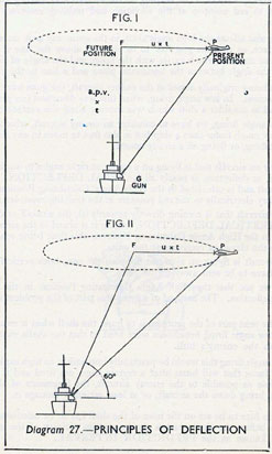
Principles of Deflection. Diagram 27.
421. When calculating deflections in high angle firing, it is always assumed
that the aircraft is flying at a level height and constant speed.
Let us first consider that the enemy aircraft flying towards the ship is such
that its future position, i.e., when the shell bursts, is directly above the gun (see
Fig. I. Diagram 27).
From the Diagram, P is the present position of the aircraft.
F is the future position of the aircraft, directly above the gun, G.
422. The height of the aircraft can be measured and the time of flight (t) from
G to F is also known, so that we know the average speed of the shell as it travels
from G to F.
This is called AVERAGE PROJECTILE VELOCITY (a.p.v.) and the
distance G F is this velocity multiplied by the time of flight (a.p.v. x t ).
The speed of the aircraft (u) is estimated by the Control Officer and if the
aircraft is to travel from P to F during the time of flight (t) of the shell, the
distance P F must be u x t
The deflection or aim-off must therefore be the angle P G F, which can be
calculated from the ratio (u X t)/(a.p.v. X t) or u/(a.p.v.) and to hit the plane at F we must fire when it is at P, with the gun aimed off an amount equal to this angle.
423. So far we have considered the case of one aircraft coming from a certain
direction, and flying so that its future position when the shell burst is directly
over the gun.
If, however, we go further and imagine that the aircraft can come from any
position, as long as its future position is at F directly over the gun, we find that P,
the present position of the aircraft can be anywhere on a circle, whose centre is at F
and whose radius is u t.
Now let us suppose that the aircraft is such that its future position F, instead
of being directly overhead is at 60° from the horizontal (see Fig. II, Diagram 27).
Once again this aircraft is flying at a constant height towards the ship and
can come in from any position on the circle with centre at F and radius u t.
150
424. If, however, we look at this circle from the gun G we notice that it now
appears to be an ellipse and not a circle, as was the case when the future position F
was directly overhead.
It can also be imagined that the circle becomes a thinner and thinner ellipse
as F approaches the surface of the sea. If the speed of the aircraft is greater,
then the circle becomes larger because u x t, which is the radius of the circle,
becomes larger.
This principle, which is called the ellipse method of calculating deflection,
is used in all existing long range high angle control systems.
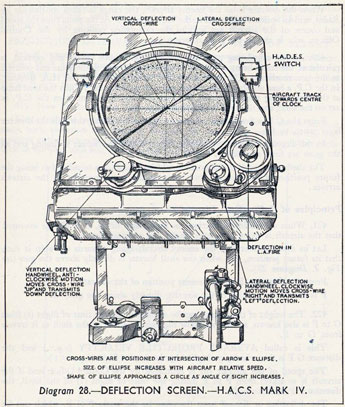
425. In Diagram 28 will be seen a picture showing the deflection screen of an
H.A.C.S. IV table. An optical system inside the table throws on to the screen the
image of a circle, which is engraved on a plate. This circle can be tilted by a
mechanism, according to the angle of sight and will thus show on the screen as
an ellipse, whose shape will vary according to the angle of sight.
151
The optical unit inside the table is moved according to u/(a.p.v.) so that any
variations in these will show on the screen as changes in the size of the ellipse.
The track of an aircraft is also shown on the deflection screen by means of a
wire, which is pivoted at the centre and rotated in agreement with an arrow in the
Control Officer's binocular. The Control Officer, in the H.A. director, keeps
this arrow along the fuselage of the aircraft and thus the correct track is sent
down to the deflection screen.
426. The deflection screen operator sits facing the screen, looking at the
ellipse. He has two handwheels, one either side of the screen, marked Vertical
Deflection and Lateral Deflection. These are connected to wires, which can
be moved across the face of the screen. The duty of the deflection screen operator
is to keep these deflection wires over the intersection of the wire marking the track
of the aircraft and the ellipse. By moving the deflection wires from the centre
of the ellipse to the point of intersection, the deflection screen operator measures
the vertical and lateral deflection of the aircraft and sends these away to the red
pointers at the elevation and training receivers at the high angle guns and so gives
the guns the necessary "Aim-off," both for elevation and training.
H.A.C.S.-FUZE PREDICTION.
427. In the beginning of this chapter we saw that, besides allowing for "Aim-off," a fuze had to be set on the shell, so that it would burst at the future position
of the aircraft.
In order to do this, we must have some means of finding out what the range
of the aircraft is going to be when the shell arrives. In H.A.C.S. this is done
by " Prediction," that is to say that we measure the present range of the aircraft
continually and by means of a range plot at the opposite end of the H.A. table
to the deflection screen, we note the way in which that present range is altering
and from this we forecast what the range will be in the future. This is done as
follows:-
428. Mounted in the H.A. director is a High Angle Rangefinder. This works
on the same principle as the L.A. rangefinder, inasmuch as the deflecting prism
inside the instrument is moved for range but the operator moves his Working Head
for height. The reason for this is fairly obvious, because if the working head were
connected directly to the prism of the rangefinder, the operator would have to
move the working head continually, owing to the fact that the rate of change of
range of an aircraft is extremely high, owing to its speed. The rangefinder is,
therefore, designed so that the operator only has to move his working head when
the aircraft changes height and as long as the height is correct, the change in the
angle of sight to the aircraft, as the director layer keeps on, operates a mechanism
in the table, which converts this measured height into range. This moves the
prism in the rangefinder and also goes to the range plot in the H.A.C.S.
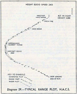
429. This observed range appears in the range plot as a series of short
lines, which slope across the moving paper of the plot. The "pricker"
underneath the plot is operated when the rangetaker in the H.A. director presses
the "cut push" with his foot.
The observed plot is liable to be irregular, especially when the rangetaker
throws off and re-cuts on the aircraft or through any errors in aim on the part of
the director layer, and this irregularity makes it difficult to predict the future
range from its slope.
In order, therefore, to get a plot with a smooth slope, another plot is introduced on the paper, called the generated plot. This is produced by the operators
on the table keeping pointers to the "mean" of the observed readings, for both
152
angle of sight and height. The generated plot appears in the range plot as a
series of lines about twice as long as those of the observed plot.
430. A third pricker is also operated by the Radar set. The Radar aerials are
mounted on the H.A. director and are pointed at the aircraft, when the layer and
trainer get on. Continual ranges are taken by Radar and these appear on the
range plot as a series of small holes.
The range plot operator, therefore, sees on his plot, three sloping plots (seeDiagram 29).
(i) The observed plot.
(ii) The generated plot.
(iii) The Radar plot.
He then, by means of a handwheel at the end of the table, moves a cursor
with a length of wire attached to it, until the wire is placed in such a position
that the knob on the end of the cursor is a continuation of the slope of the plots.
431. The operator aligns his cursor parallel to the slope of the generated plot
and over the latest readings of the observed plot; if the Radar plot is working
accurately, he uses this plot rather than the other two.
By moving his handwheel the plot operator sends away to the fuze setting
receivers at the guns continual fuze numbers for the predicted future range of the
aircraft. At the guns these fuzes are set when the " load " lamp lights at the
receiver. The load lamp is worked automatically by the H.A. table at regular
intervals, as is also the fire buzzer, which tells the director layer when to fire the
broadside, whose shell are fuzed for the correct future range.
153
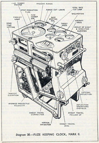
FUZE KEEPING CLOCK-FUZE PREDICTION.Diagram 30.
432. The fuze keeping clock is fitted in destroyers and small ships, to solve
the long range high angle problem. The deflections, both vertical and lateral,
which provide the necessary "Aim-off" for the guns, are produced on the same
principle as in H.A.C.S., except that the deflection operator looks through a hole
at the end of the clock at the ellipse, instead of watching the ellipse on a screen.
154
433. The method of obtaining fuze-settings is, however, different and is as
follows:-
In the director is a rangefinder. This rangefinder takes ranges of the aircraft
continually, when the director layer and trainer are on; in order that the rangetaker will not have to move his working head continually as the range alters,
the deflecting prism in the rangefinder is moved automatically by the F.K.C.
This is done by means of a "Rate Clock," which works on the same principle as
the rate clock in the Admiralty Fire Control Clock, which is used for low angle
firing, that is to say, when the inclination and speed of the aircraft is set on the
F.K.C., the rate of change of range is calculated, which in turn, moves the deflecting prism in the rangefinder. Thus, as long as the correct settings are passed down to the F.K.C. by the Control Officer in the director, the rangetaker will find that his cut is being held the whole time.
434. Thus we get the present range of the aircraft being sent down continually to the F.K.C., the rangetaker pressing a cut push with his foot when he has
la cut. At the same time Radar aerials mounted in the director are pointed at the
aircraft.
Future range, however, is required in order to set the correct fuze at the gun
and this is calculated by the mechanism in the F.K.C., which works out the enemy's
travel during the "Dead Time" and "Time of Flight" of the shell and
hence calculates the future range.
435. In the mechanism of the F.K.C. is an instrument similar to that in the
H.A.C.S., called a FIRING INTERVAL CLOCK, which burns the PREDICT
LAMP on the F.K.C.
The fuze number is then read off from a rotating disc at the opposite end of
the clock to the deflection operator and the fuze sent to the guns via a fuze transmitter on the bulkhead in the T.S. Thus the correct fuze for the future range is
passed to the fuze setting receivers at the guns. The guns are then loaded with
the correctly fuzed shell; and a fire buzzer sounds in the director, telling
the director layer when to fire.
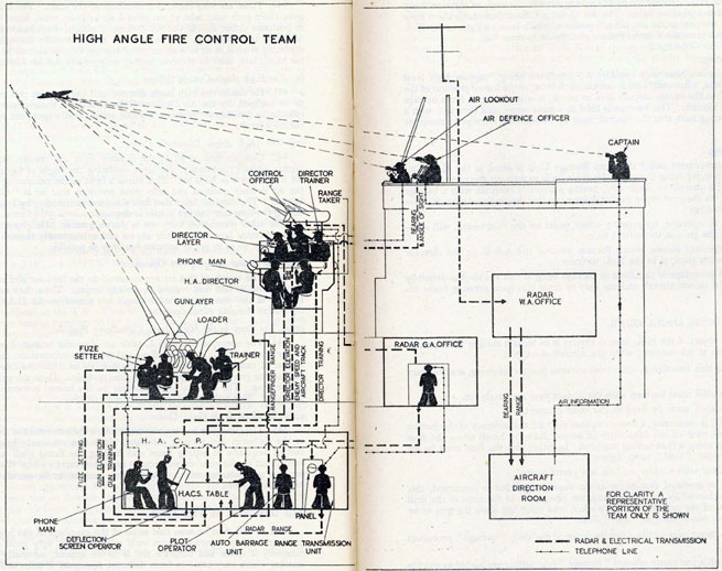
THE HIGH ANGLE FIRE CONTROL TEAM. Diagram 31.
Composition of the Team and Air Defence of the Ship.
436. As in low angle firing so in high angle firing, the successful defence of the
ship against hostile aircraft is brought about only by good teamwork, backed up
by constant practice and an understanding by each member of the team of the
difficulties and complexities of each other's jobs.
The high angle control team is as follows:-
(i) The Air Defence Officer.
437. He is the captain of the team and on him rests the responsibility of seeing
that no enemy aircraft approaches without being engaged. He chooses the targets
to be engaged from the air defence position at the rear end of the bridge and by
means of the Air Defence Officer's Sight, indicates the approaching enemy
aircraft to whichever H.A. director he wishes.
(ii) The Assistant Air Defence Officer.
438. Assists the A.D.O. and operates the A.D.O.'s sight on the other side
of the air defence position.
"(ii) a. The Target Indication Officer.
He is responsible for the Air Defence of the ship in Blind Fire. He is
stationed in the Aircraft Direction Room, which is part of the Action In formation Centre, and by means of the Target Indication Unit (see paragraph 446)
he passes ranges and bearings of Aircraft Targets, detected by Long Range
Warning Radar, to the appropriate H.A. Director and Transmitting Station."
(iii) The Long Range Warning Radar Set Operators.
439. This Radar set is designed to pick up aircraft flying either singly or in
formation at long ranges. The information that it receives is passed to the
Action Information Centre, and thence to the A.D.O.
155
(iv) The Air Look-outs.
440. These are very important members of the team. There are six air lookouts, three each side, who sit on special air look-out seats, fitted with binoculars,
in positions either side of the Air Defence Position. Each look-out has an arc for
which he is responsible. He sweeps that arc continually through his binoculars
reporting as soon as he sees an aircraft. Having seen an aircraft he must keep it in
his binoculars, until he receives further orders from the Air Defence Officer.
(v) The High Angle Control Officer.
441. He sits in the high angle director and having been put on to the aircraft
to be engaged, by the Air Defence Officer, he gives the necessary orders to the
calculating position for opening fire and subsequently spots the bursts on to the
enemy aircraft.
(vi) The High Angle Director's Crew.
442. Consists first of all of the director layer and trainer, who keep on the
enemy aircraft continually, the layer operating the angle of sight cut push with
his foot as soon as he is on. This burns a light in the calculating position and in
the air defence position and tells these positions that he is "On" the enemy
aircraft. The director layer also fires the guns electrically, by means of a trigger,
during the time that the fire buzzer is ringing.
The other member of the crew is the rangetaker. He gets a "cut " as soon
as the director layer and trainer are on and subsequently throws off and re-cuts
continually, so as to get as accurate readings as possible.
(vii) The Radar Ranging Set Operators.
443. The aerials of this set are mounted on the director and are moved when
the director is laid and trained on to the target. Thus they are pointed continually at the enemy and Radar ranges are passed to the H.A.C.S. Plot, from
the Radar Ranging panel operator.
(viii) The Crew in the High Angle Calculating Position.
444. The operators of the H.A. table are given the estimated course and speed
of the aircraft by the Control Officer and from this information, together with the
measured range and movements of the director as it follows the target, are calculated the gun elevation, training and fuze number. These are passed continually
to the guns. The H.A. table also sounds the fire buzzer automatically at regular
intervals. This tells the director layer when to fire.
(ix) The High Angle Guns' Crews.
445. The gunlayers and trainers must follow the movement of electrical pointers
in the elevation and training receivers. It is also extremely important that the
correct sequence of setting fuzes and loading the fuzed shell into the guns is
carried out by the guns' crews, because each shell carries a fuze that is only correct
for that particular moment. These points must never be sacrificed to achieve a
higher rate of fire.
AIR DEFENCE OF THE SHIP.
446. It will then be seen that some of the members of the high angle control
team are widely separated from each other, so that very good co-operation is
necessary if quick and accurate fire is to be opened, especially against enemy
attacks, which may come in from different directions at once and may give very
little warning of their approach. The Air Defence Officer receives all the available
information from the Action Information Centre, when hostile aircraft are reported,
and he can then get the H.A. directors on to the best possible look-out bearings.
When a formation is sighted he immediately trains his sight on to it, sending
156 and 157
158
away elevation and training by Evershed to whichever H.A. director he decides.
As soon as the H.A. director has picked up the aircraft, the angle of sight cut lamp
in the air defence position lights. The Air Defence Officer then closes the "open
fire switch," situated in the air defence position, which burns a light in the H.A.
director. This gives the Control Officer permission to open fire.
"At night or in thick weather neither the Air Defence Officer or the
H.A. Directors will be able to see the enemy Aircraft, so the responsibility for
the Air Defence of the Ship rests with the Target Indication Officer. This
officer is stationed in the Aircraft Direction Room situated below decks and
part of the Action Information Centre. He is assisted in his task. by an instrument called the Target Indication Unit (T.I.U.), worked by four operators.
This unit is linked with a Long Range Warning Radar and gives a picture of all
targets within range of the set. The T.I.U. has a number of handwheels
(depending on the type of ship) for transmitting Relative Bearing to the
appropriate H.A. Director or Close Range Group and can also transmit range
by Range Transmission Units on either side of the Radar Display.
There are also switches for controlling Call-up Gongs in the Air Defence
Position and H.A. Directors, and the Check Fire Bells at the guns."
Barrage Firing.
447. So far we have only considered " predicted firing " against high level
bombing attacks, when each fuze is calculated to burst at the future position of the
aircraft. When the enemy aircraft dive to attack, it is necessary to fire a barrage
ahead of the aircraft. This barrage is fired at a fixed range, and therefore with a
fixed fuze setting such that the aircraft must fly through the barrage to complete
its attack.
A.B.U. Firing.
448. An instrument called the Auto Barrage Unit is fitted in the H.A. Calculating Position for firing the guns. Its function is to measure the rate of change
of range of the aircraft by Radar and, having previously been set with a barrage
range, it will fire the guns at the correct moment so that the shell and aircraft arrive
at the same instant.
The A.B.U. operator, by pressing a foot pedal on the instrument, will automatically fire the guns at the correct time.
The change-over switch, which decides whether the A.B.U. or the director
layer will fire the guns, is in the H.A. director.
The great advantage of this form of barrage firing is that the shell is definitely
fired to hit the enemy aircraft and not only to deter him from pressing home his
attack.
DRILL AT HIGH ANGLE GUNS.
449. The object of the H.A. control system is to burst a shell at the aircraft's
future position at the moment when the aircraft reaches it.
To achieve this, two things, apart from accurate pointer following, are necessary
at the gun:-
(i) The shell must be fired with the correct fuze accurately set.
(ii) The shell must be fired at the right moment.
So far as (i) is concerned, a heavy responsibility for the accuracy of the gunfire
against aircraft rests on the fuze-setter (if setting fuzes by hand) or on the fuze
follower when using a fuze-setting machine. In either case the fuze must be set
immediately the " load " lamp lights.
A round fired with a badly set fuze is a round wasted.
It will be appreciated that so far as the second condition is concerned, this
can only be achieved by the closest attention being paid to the time of the drill
by the captain of the gun and the trayworker, who must not allow the gun to be
loaded with an out-of-date or "stale" fuze.
When the target gets within a certain range of the ship, "barrage" procedure
may be used.
Rounds with a previously ordered "barrage" fuze setting are loaded as quickly
as possible, whenever the gun fires.
450. The gun may also be required to engage a target in "local barrage," in
which case the gun is aimed by the gunlayer and trainer, using eyeshooting sights
159
or their equivalent, and rounds set to the barrage fuze are loaded and fired, locally,
as quickly as possible'.
In H.A. as well as L.A. fire it is important to realize that what has to be learnt
by the gun's crew is the action required of them on receiving any given order and
not a set sequence of orders, which may vary in action.
455. Close range weapons are used against low flying or diving aircraft,
moving at very high speeds at close ranges (3,000 yards and below). The time
during which the enemy is within range is very short, so that it is important for the
control of these weapons to be simple and if possible under the direction of one
man.
The guns are in all cases designed to fire very rapidly, with a high muzzle
velocity, and are capable of being swung quickly when following an aircraft or for
picking up a fresh attacker.
CLOSE RANGE GUNS' CREWS.
456. The crews of the close range weapons are the "commando troops" of the
ship. They have got to be tough, well disciplined, and capable of withstanding
hardship. They are not protected from the weather or splinters and have got to
be able to keep cool and collected, and shoot accurately in spite of all that is going
on around them.
Strict discipline at close range weapons is essential, otherwise, in action you
may easily become distracted, or be caught napping by a surprise attack.
457. The following are the usual faults apparent in air battles and must be
guarded against:-
(i) When excited, men are apt to forget to aim accurately and usually miss
astern.
(ii) In the excitement, men are apt to forget the fact that our own fighters
are in the vicinity.
(iii) When excited, men are apt to look at events happening which have
nothing to do with them and, as a result, they are caught napping by
an enemy aircraft which suddenly dives at them from some other direction. You must always anticipate the next attack.
It is essential for all close range weapon- crews to keep a look-out. Do not
rely on the Air Defence Position to see the enemy or to communicate with you,
or the bridge to tell you when to open fire. You must be ready to open fire on your
own at the correct target as soon as it is within range.
Close range weapons are usually to be found in the most exposed positions in
the ship so that they can have the best arcs of fire. This is all the more reason
why they and their ammunition must be scrupulously clean.
161
CLOSE RANGE GUNSIGHTS.
458. The latest method of sighting close range weapons is by using gyro gunsights. All that need be said about them in this book is that steady aiming and
constant practice are essential. The other method, which is the "stand-by"
method, is "Eyeshooting."
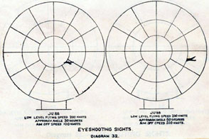
EYESHOOTING. Diagram 32.
459. "The Eyeshooting Pocket Book" (B.R. 254) contains full information
regarding the principles and application of eyeshooting sights on close range
weapons and should be thoroughly understood by all crews. You can buy a copy
of it for a few pence, or borrow it from the Gunnery Office.
As applied to close range anti-aircraft weapons, the word " eyeshooting "
simply means the method of aiming in which the aimer judges by eye and without
any calculating instruments where to point his gun, in order to hit a moving target.
There is nothing difficult nor new in the principles of eyeshooting with A.A.
weapons; the mode of operation is similar say, to throwing a boot at a cat running
along the top of a wall. To allow for the movement of the target during the time of
flight of the bullet, the gun has to be pointed ahead of the target at some position
along its future path.
Foresights.
460. Looking at the eyeshooting foresight in Diagram 32, you will see that it
consists of a number of equally spaced rings, one, two and sometimes three (see
also Diagram 35).
In the case of all modern sights the inner ring is the 100 knot ring, the next
one the 200 knot ring and the third one, if fitted, the 300 knot ring.
Note. In the older type of sight there was also a very small ring around the
centre of the sight. There was no special use for this ring and it is no
longer fitted.
162
461. The object of these rings is to provide you with a scale for applying the
amount of aim-off speed you have estimated. The 100 knot ring shows you the
amount of aim-off to take for an aim-off speed of 100 knots, the 200 knot ring shows
you how much to allow for 200 knots aim off and so on. In fact, the rings are
aim-off speed rings. For aim-off speeds other than the exact figures of 100, 200 or
300 knots, say, 30, 160, 250 or 330 knots, you have to gauge the distance between
(or outside) the metal rings of the sight which simply give you a scale of aim-off
speeds.
462. The method of using the sight is very simple. Look at the aircraft,
note its direction of flight and estimate its aim-off speed. Point the gun so that
the aircraft is flying towards the centre of the sight, with its nose the distance
from the centre corresponding to your estimate of its aim-off speed. As the
attack develops and the aim-off speed increases, bring the nose of the aircraft
further and further out from the centre, always adjusting direction of aim-off to keep the aircraft flying towards the centre of the sight.
To assist you in applying direction of aim-off correctly, when the amount of
aim-off is large, some sights have " radial wires " pointing towards the centre from
the outer rim of the sight. These are valuable because, although wrong estimation
of aim-off speed is the most common cause of missing the target, misses are due
quite often to incorrectly gauging the direction of aim-off, particularly when the
aim-off is large.
At weapons which may have to be used against surface craft, you will find
"ticks" fitted at 10 or 20-knot intervals along the horizontal and vertical crosswires inside the 100 knot ring. These are to assist you in holding the correct
point of aim after you have found it by spotting.
Backsights.
463. Most backsights are of the aperture type with rubber eyepiece. Having
placed your eye correctly in the eyepiece, you can forget about the backsight
and concentrate on pointing the foresight in the correct direction. You must,
however, be quite certain first that you have centred your eye correctly in the
eyepiece, otherwise you will introduce an error in your aim. In modern backsights
there are crosswires or crossed cards to assist you to centre your eye. A glance
at them just before you take aim will enable you to put your eye correctly on the
line between centre of foresight and centre of backsight. Having got it central,
keep it central.
In the heat of action unless you guard against it, unbeknown to yourself, you
will aim without putting your eye to the backsight. This is fatal, so see that it
does not happen.
464. At certain weapons "bead" backsights are fitted. The principles of eyeshooting with these sights are the same as with aperture sights but you keep your
head well to the rear, so that you can see the bead, the foresight and the target
all at the same time and instead of keeping your head in a fixed position, you
have to move it about as necessary to take aim.
To take the correct aim with a bead backsight, the bead must be covering the
nose of the aircraft, when the nose of the aircraft is where you want it in the
foresight.
In the case of the Oerlikon gun, which vibrates greatly when firing, you will
find that although there is a fitting for a rubber eyepiece fitted to the backsight, you
have to keep your head well to the rear and use it like a bead backsight. The sight
is designed to be used in this way; the rubber eyepiece should not be on the
sight.
163
AIRCRAFT RECOGNITION.
465. There are three things you must learn about enemy aircraft, viz.:-
To be able to recognise them.
To know their speeds.
To estimate their range.
Recognition.
466. You must be able to recognise aircraft for the following reasons:-
(i) So that you will know whether it is an enemy aircraft or a friendly one,
since you may have to decide for yourself whether or not to fire at it.
(ii) So that you will be able to judge its approach angle, especially if the
approach angle is small.
(iii) So that you can make a good guess at its speed.
You should take a pride in your ability to recognise aircraft and to judge
approach angle. Get hold of any cards, models, pamphlets, newspapers or
magazines that you can and study them carefully. Do not try and learn too many
types at once but get to know the three or four types in general use really well;
then you can start adding to your collection as other types come into use. Some
credence should be given to the opinions of youths in this matter; some of them
have surprisingly accurate knowledge.
Estimation of Speed.
467. As you have previously read, you must know the flying speed 'of an aircraft before you can estimate the aim-off speed correctly. judging the speed of an
aircraft depends almost entirely on knowing the performance of the different
types and you must learn this when you are studying how to recognise aircraft.
Unless you have had very considerable experience, you will not get much
assistance in judging speed from the noise of the aircraft or from looking at it,
except that it obviously goes faster when diving. You can generally assume that,
when attacking, your target is going at full speed but do not forget that, if diving,
it will probably be going much faster than its full level flight speed.
A good rule for judging aircraft speeds at the present time is given below,
although new types coming into service may not fit into this rule.
Type of Attack.
468.
Fighter
450 knots
Dive-bomber
350 knots
Low level bombing
350 knots
Torpedo attack
250 knots."
Estimation of Range.
469. You should be able to estimate the range of an enemy aircraft by eye
in order that you will know when to open fire.
The estimation of range depends entirely on practice and experience, and
you must get all you can. You must remember that varying weather conditions and
differences in the sizes of aircraft may produce misleading effects. For example,
if you are used to dealing with medium-sized aircraft, you will tend to under-estimate the range of a larger aircraft and open fire too early. Therefore, when
studying recognition, you must note which are large machines and which are small
ones. Very often recognition drawings and silhouette cards do not make this
point clear, but you can spot it at once with the models.
164
165
470. To check your estimate of range when you are learning, a simple instrument called the " A.A. Range Indicator " can be used, preferably by an instructor
or another person. There are two types of this instrument but they both work
on the same principle, namely, that you hold a plate at arm's length and where the
aircraft fills the aperture, you read off the range. You will not be able to use this
instrument in action if you are manning a gun, so you must learn to estimate the
range by eye.
The "Maximum Effective Ranges" of close range weapons are as follows:-
2-pdr. multiple Pom-Pom and Bofors in local control
1,700 yards.
Oerlikon 20 mm. single gun
1,000 yards.
0.5 in. Machine gun.
800 yards.
0.303 in. and 0.30 in. weapons
400 yards.
Note. Against approaching targets, fire should be opened when the present
range is some 200 or 300 yards greater than the above figures.
Consider a fighter aircraft approaching at 300 knots. It covers a nautical mile
(2,000 yards) in 12 seconds. It is within effective range of a .303 machine gun
for 400 yards coming towards, and 400 yards going away, a total of 800 yards
which it can travel in under five seconds. You haven't much time, have you?
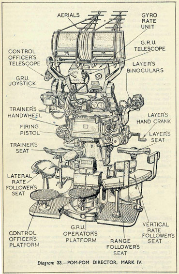
THE POM-POM DIRECTOR MARK IV. Diagram 33.
471. In earlier types of Pom-Pom directors, the necessary "Aim-off" at the
director and thus at the guns was done by " eyeshooting."
In the Pom-Pom Director Mark IV (see Diagram 33), the eyeshooting principle
is abandoned and the target's vertical and lateral movement is measured by an
instrument called the GYRO RATE UNIT. These movements are combined
with the time of flight of the shell and produce vertical and lateral deflections.
The transmission from the director to the Pom-Pom is by remote power control,
whereby the Pom-Pom mounting automatically follows the director.
472. The Pom-Pom director has a full crew of eight men, whose duties are
as follows:-
The Control Officer.
The Gyro Rate Unit Operator.
The Director Layer.
The Director Trainer.
The Vertical Rate Follower.
The Lateral Rate Follower and Communication Number.
The Range Follower.
The Radar Operator (in Radar Office).
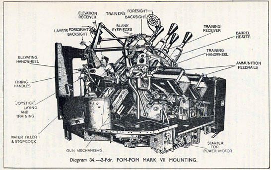
THE 2-PDR. MARK VIII GUN ON THE MARK VII MOUNTING.Diagram 34.
473. This Multiple Pom-Pom has four barrels and is found in destroyers and
cruisers.
The mounting may be fitted with or without a Pom-Pom director, and in the
former case, laying and training is by remote power control. As a general rule,
Pom-Pom directors are fitted in cruisers and not in destroyers.
166
167
The crew consists of eight men. The captain of the gun is in general charge
and operates the firing clutch lever. The remainder of the crew are gunlayer,
trainer, ammunition feed numbers and loaders for right and left guns.
Ammunition is supplied in belts; eight belts per gun, each belt consisting of
14 rounds, are loaded on to the feed rails. The first and last round of each belt
rests on the rails and are connected to the next belt by connecting links. The
remainder of the belt hangs in a bight.
Mounting fitted with Remote Power Control.
474. The motive power of mountings fitted with R.P. 50 remote power control
is electric. An indicating lamp is fitted at the mounting to show that this source
of supply is flowing.
When in director control, a power change-over switch at the mounting is put to
DIRECTOR and the mounting will automatically follow the director and the
director will fire the guns, when the firing clutch lever is put to ELECTRIC.
Note. Any or all guns may be put to SAFE, by means of interrupter levers
at each gun. Normally these are to FIRE.
If it is necessary to bring the mounting back to a convenient position for
loading, this is done by putting the power change over switch to LOCAL
from DIRECTOR and taking over the control of the mounting with a joystick,
fitted at the mounting. The mounting can also be fired by means of a local firing
trigger on the joystick, when being laid and trained by the joystick.
Mounting fitted Without a Director.
475. In this case, laying and training is by hand, the gunlayer and trainer using
eyeshooting sights. The guns can be fired either by "Hand" or "Electric"
depending upon the position of the firing clutch lever. In "Hand" the guns
are fired by turning the hand firing gear, in "Electric," pressing the local
firing pistol energises a circuit, which clutches the firing motor to the firing cam
and fires the guns.
The latest type of mounting fitted without a director is power-controlled by
means of a joystick on the mounting.
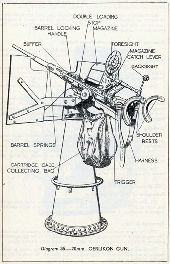
THE 20 m.m. OERLIKON GUN.Diagram 35.
Description of Gun and Mounting.
476. The Oerlikon is an automatic gun designed for close range anti-aircraft
fire, with an effective range of 1,000 yards. It is mounted on a single shoulder-controlled mounting, or on a twin power-operated mounting.
Operation of Gun.
477. The gun is operated by the pressure set up by the explosion of the round.
The empty case is blown back against the breech, forcing it to the rear against the
pressure of the barrel springs, which carry the moving parts forward again.
The breech is not locked at the time of discharge and the round is fired a
fraction of an inch before it is fully home in the chamber, the neck of the case
swelling to form a gas seal.
The barrel and casing do not recoil; the whole force of the explosion is utilised
in propelling the projectile and operating the moving parts.
168
169
Loading.
478. The gun is cocked by means of the cocking lanyard.
The gunlayer presses the magazine catch lever as far forward as it will go,
otherwise the interlock mechanism will not be cocked. It is essential that the
magazine catch lever be pushed fully forward, either by the knuckles or finger
tips, as few men have sufficient arm length to push the catch lever fully forward
with the palm of the hand, when behind the shoulder piece in the firing position.
If the lever is not pushed right forward, the catch will not be cocked, with the
result that the magazine interlock will still render the firing gear inoperative.
The loading number places a loaded magazine in position forward end first
and swings the rear part of the magazine down smartly to seat it; the lever is
automatically released, locking the magazine in position. The action of shipping
the magazine presses down on the ends of the catch and releases the magazine
interlock from engagement with the trigger gear and the gun can then be fired.
It is possible to remove an empty magazine and ship a fresh one although the
magazine catch lever has not been pushed as far forward as it will go. In this
event the magazine interlock gear will not have been released and the gun will
not fire.
Automatic Firing.
479. With the gun cocked and a loaded magazine in position, a full round is
lying in front of the breech face ready to be driven into the gun.
With the safety catch lever to FIRE, pressing the firing lever releases the
breech mass, which flies forward under the action of the barrel spring, driving the
live round into the chamber.
The breech mass at the instant of firing is still travelling forward. The force
of the explosion, as far as the rearward direction is concerned, is then absorbed in
checking this forward movement and reversing its direction, against the action of
the powerful barrel springs.
On firing, the empty case is blown back against the breech face piece, forcing
the moving parts of the gun to the rear, so compressing the barrel springs. (The
moving parts consist of the breech, the bolt, cotter, two breech bars, and barrel
spring casing, and they, being held together by the cotter, move as one part.)
480. The force of the explosion has now been overcome and the barrel springs
are fully compressed and buffering of the extreme rearward movement has taken
place.
As the barrel springs, assisted by the buffer springs, exert themselves, the run
out commences. If the firing lever is held to FIRE, the top of the breech face
piece will pick up a fresh round from the magazine during its run-out movement
and the cycle of operations will be repeated until the magazine is empty.
Holding back the Breech Mass after the Last Round in the Magazine
has been Fired.
481. A catch automatically holds the breech mass in its rear position after
the last round in the magazine has been fired, so that when the empty magazine
has been exchanged for a full one, it is not necessary to cock the gun as on the
first occasion. The gun is held cocked and it is only necessary to cock the magazine
catch lever and ship a fresh magazine.
170
The Double Shoulder Piece on Shoulder-controlled Mountings.
482. The double shoulder piece, which is adjustable for width and is fitted
at the rear end of the casing by a bayonet joint, together with the harness fastened
round the body, gives adequate control of the mounting enabling a rapidly moving
target to be followed with precision. Accuracy of aiming is very largely dependent
on smooth footwork which requires constant practice.
Balance Spring.
483. To assist in easy elevation of the gun, a spiral counter-balance spring is
provided at the left hand side of the bracket. At the front end of the cradle the gun
lies in a " shoe " in which it is held fast by a securing bolt; this gun securing bolt
takes the thrust of the gun when fired and care must be taken that the bolt engages
properly with the underside of the gun and that it is kept greased and functioning
correctly. The cradle can be secured in the horizontal or vertical position by the
stops provided. If a gyro gunsight is fitted, it should always be left horizontal.
The Drum Magazine.
484. With each gun are supplied six drum magazines, each capable of holding
sixty rounds, one loading stand and two ratchet levers for tensioning the magazine
spring.
Every possible care must be taken to avoid damage to the magazine, otherwise
failures will almost certainly result.
Before loading a magazine it should be tested for freedom of its moving parts
by first ensuring that the tension indicator is showing zero, after which the ratchet
collar should be lifted and the axis shaft rotated through its full travel by means
of the boss on the centre of the ratchet lever handle.
If the muzzle covers provided are in use, the following precautions must be
taken.
The last two rounds to be loaded into magazines are to be either practice or
practice tracer rounds, so that the first round to be fired will carry away the muzzle
cover and the second will do so in the event of the first round missing fire. H.E.
ammunition would give a premature on hitting the cover.
Grease on Ammunition.
485. Ammunition supplied in boxes is not greased.
For the gun to function it is essential that each round should be lightly
greased with Grease No. 0 before loading into the magazine. This should be done
by hand and not with a brush. Oil is not to be used.
A little grease applied shortly before firing to the cartridge case visible in the
mouth of the magazine helps.
To Charge a Magazine.
486. Place the magazine upon its side on the loading stand, pulling up the
ratchet collars. By applying the ratchet lever with the boss on the centre of the
ratchet lever engaged with the pin within the ratchet collar, and turning the spring
axis, wind the feeder block to the opening of the magazine.
Insert the rounds, pushing them in with the thumb and taking particular care
that the feeder block remains in contact with the first round inserted, and that
none are allowed to fall forward after being inserted.
171
If this should happen the magazine will require to be stripped. The feeder
block should be moved inwards slowly during charging, by operating the ratchet
lever; in this manner the feeder block is controlled, so that it cannot move a greater
distance at one time than is required to insert one round.
When the magazine has been charged, the ratchet collar is allowed to go down,
permitting tension to be applied by the ratchet end of the lever.
Tensioning the Spring.
487. When the magazine is fully loaded with 60 rounds it should be fully tensioned by rotating the magazine lever as far as possible.
Should the magazine be partly loaded, e.g., 30 rounds, it is to be tensioned
until the indicator reads 30, followed by two further clicks on the ratchet. To put
tension on a magazine loaded with less than 60 rounds, it is necessary to
hold the ratchet collar, while using the ratchet lever.
Care must be taken that the magazine interlock plunger is free, otherwise the
breech block will not remain in the rear, i.e., cocked, position when the last round
is fired from the magazine. This plunger is spring loaded and is situated at the rear
of the magazine cartridge feeder.
If a magazine is loaded only to be stored, the spring is merely given a slight
tensioning.
Make sure that the magazine is fully tensioned before placing it on the gun.
If this is not done stoppages will result.
Should the magazine be given no tensioning at all, the rounds would be liable
to fall out or become disarranged in the magazine when removing it from the
loading stand.
To Release the Tension on the Spring.
488. If a magazine that has been charged and tensioned is not required for
ready-use purposes, the tension is to be released to that small amount which is
necessary, as described above, to prevent the rounds from becoming disarranged.
To do this:-
(i) Ship the ratchet lever and take the weight of the spring by the lever,
while lifting the ratchet collar.
(ii) Allow the lever to revolve under the action of the spring, until it
approaches the lifting handle.
(iii) Engage the ratchet collar, replace the ratchet lever in the former position
and continue, for as long as necessary, until the indicator show
about 15.
To Unload a Magazine.
489. If it is desired to unload a charged and spring-loaded magazine, it should
be placed on the loading stand and the rounds pushed out one by one, by hand.
This relieves the pressure of the spring at the same time.
If the magazine is charged but not tensioned, it must be tensioned before
unloading, so that the spring may force the rounds forward to the opening.
Caution.
490. Ammunition is greased and care must be taken to see that the grease
which is in sight in a loaded magazine is not removed. This grease is necessary
for the functioning of the loading arrangements.
172
Maintenance.
491. The following are the routines which should be carried out with the
Oerlikon gun:-
Daily.
Remove magazine. Sponge out bore, taking particular care to see that the
chamber is left clean and greasy. Lubricate breech and breech block guideways
in magazine opening without easing the spring.
Weekly.
Remove magazine. Ease the barrel springs and lubricate the top of the breech.
Remove the shoulder piece, hand grips, the trigger cover plate and trigger casing,
drain out any water in the gun body. Lubricate the trigger mechanism and reassemble. Cock the gun, ease springs again and recock.
After Firing.
Carry out a daily and weekly routine. See that the gun securing bolt at the
front
end of the cradle is free and grease it.
492-494.
173
CHAPTER X.
LOOK-OUTS AND OPTICAL INSTRUMENTS.
LOOK-OUTS.
495. The safety of the ship and its success in action, to a great extent depends
on look-outs. Keeping a good look-out for long periods at a time is apt to become
extremely dull and tedious and will produce eyestrain. It is for this reason that
the length of a look-out's trick is reduced as much as possible and, if sufficient men
are available, this trick should be cut down to 20 minutes.
This period is not too long and if you are detailed as a look-out in your ship,
you must realise the very essential and important task that you are performing, and
keep strictly to the routine that you are taught.
Before considering the actual look-out routines that are carried out, it is essential
that the look-out should have a thorough knowledge of how to use his binocular.
CARE OF BINOCULARS.
496.
(i) It is essential that binoculars should be correctly cleaned before use
and that the glass of both the eye lens and object glass should be
kept clean and free from moisture.
(ii) Binoculars are easily damaged and must be treated carefully. They
should be carried to the position in which they are to be used in
their leather case, and should be kept in the case when not actually
in use. The lens hoods are particularly fragile.
(iii) If binoculars or their cases get wet, they must be dried carefully before
being stored away.
(iv) Each pair of binocular is fitted with a strap and lanyard. Unless a
binocular holder is being used, both strap and lanyard must be
worn round the neck.
(v) If a leather cup piece is fitted, use it to protect the eye lenses from
rain and spray, when not actually looking through the binocular.
If there is no cup piece, use your hand.
(vi) Use something soft for cleaning or drying the glass surfaces; such
material should contain neither grit nor grease.
(vii) Do not try to strip your binocular. If they get damaged or are dirty
inside, report the fact to the Petty Officer in charge.
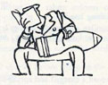
HOW TO ADJUST BINOCULARS. Diagram 36.
497.
(i) Make sure that they are clean and undamaged. If light filters are
fitted, see that they are "OUT" in both eyepieces.
(ii) To Focus. Select a fine object at-a fair distance. Rigging of another
ship is good for focusing. Screw both eyepieces fully out and
focus one eye at a time by screwing in on the eyepiece until the
object is most sharply defined. Then screw the eyepiece out again
as far as possible without loss of definition of the object.
174
175
(iii) Next adjust the interocular distance, that is to say, adjust the binoculars
so that the eyepieces are the correct distance apart for your eyes.
To do this, look through the binoculars and bend the two eyepieces
together, until only one image is seen and the eyes feel comfortable.
At night it is very essential to get this distance correct or much
less light will get through the binoculars to your eyes.
(iv) Having adjusted both the focus and the interocular distance, note the
readings shown on both the scales and remember them. Sometimes, particularly at night, it is not easy to find an object on which
to focus. Modern binoculars have " click " focusing, so remember
the number of " clicks " required to focus your binoculars; having
first of all screwed both eyepieces fully out, set them by the
"clicks." The units engraved on the eyepieces are called dioptres
and are measured plus or minus. At night use a fixed focus of
minus 1 unit (or 2 1/2 on those binoculars which are marked from
0 to 7). The interocular distance should be adjusted the same for
night as for day.
HOW TO USE BINOCULARS.
498.
(i) The binoculars must be steadied on some convenient place. Binocular
holders are usually supplied; if not, rest your elbows on the top of
the screen.
(ii) Wind shakes binoculars badly. Kneel down or get in the lee if you
can.
(iii) Prevent light from coming in at the side of the eyepieces by using
your thumbs or hands, if you are employing a binocular holder.
(iv) Leave a gap between the eye lenses and your eyes. This will prevent
the eye lenses becoming fogged. This fogging of the eye lens is
more likely to occur at night than by day and is not so likely to be
noticed, so beware of it.
(v) Use a light filter if you must, because of the glare, but never unless
you have to.
TYPICAL LOOK-OUT ORGANISATION.
499. Look-outs may be divided into the following classes:-
(i) A.A. look-outs.
(ii) Surface look-outs:
(a) Far look-outs.
(b) Near look-outs.
(c) Fog look-outs.
(iii) Night look-outs.
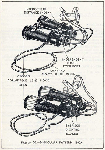
DUTIES OF LOOK-OUTS.
(i) A.A. LOOK-OUTS. Diagram 37.
500. These are stationed near the AIR DEFENCE POSITION. They v
in pairs, relieving each other every 20 minutes. Once an air look-out has sighted
an aircraft, he must not take his eyes off it until the A.D.O. has found the target.
The rating not closed up at the seat reads off the bearing and angle of sight.
A.A. look-outs are given definite "sectors" of 60° to search.
176
501. There are two A.A. look-out routines, the STANDARD ROUTINE and
the SHADOWER'S ROUTINE. The shadower's routine gives the maximum
rest to look-outs. The standard routine covers all angles of sight at which aircraft
may approach.
The STANDARD ROUTINE is as follows:-
1st period
Sweep at the elevation ordered.
2nd period
Sweep back 5° below the elevation ordered.
3rd period
Sweep back 10° below the elevation ordered.
4th period
Sweep back 15° below the elevation ordered.
5th period
Sweep the horizon for low flying aircraft and ships.
6th period
Scan the whole sector systematically from horizon to zenith using the naked eye.
Each period must take from 15 to 20 seconds.
The elevation of the 1st sweep is ordered by the Air Defence Officer,
according to the conditions.
The SHADOWER'S ROUTINE is as follows:-
1st period
Sweep at 5° elevation.
2nd period
Sweep back along the horizon, keeping it in the centre of the binoculars.
Each of the above periods takes from 15 to 20 seconds.
3rd period
Search the whole sector systematically from the horizon to zenith, with the naked eye, a horizontal sweep taking about 30 seconds for the period.
Method of Reporting.
502. On sighting an aircraft, the look-out must report:-
"Aircraft."
"Far" (or "Near").
"Approaching" ("Crossing" or "Going Away").
"Type."
177
He must then keep on following it, until he is told to carry on sweeping.
The look-out off trick, as soon as he hears the report "Aircraft " reads off and
reports:-
"Red four five."
"Angle of sight two zero"
He continues to do this until the A.D.O. has found the target.
(ii) SURFACE LOOKOUTS.
503.
(a) Far Look-outs.
Far look-outs are stationed aloft in clear weather. The sector for which each
look-out is responsible must be swept slowly and systematically keeping the centre
of the binocular field just above the horizon. The time taken for a 70 degree
sector should be from half a minute to a minute, and on completion the look-outs
must sweep back slowly with the naked eye, and repeat the sequence. Whilst
sweeping with the naked eye, they should search for the tracks of approaching
torpedoes.
(b) Near Look-outs.
Near look-outs are situated lower down usually on or near the bridge. The
same procedure should be carried out as for far look-outs, but in this case keeping
the horizon in the top of the binocular field.
(c) Fog Look-outs.
In times of extremely bad visibility or fog, special look-outs are placed as far
forward as possible. In these circumstances it is sometimes better for the sector
to be searched with the naked eye, binoculars being used only to verify a suspected
object.
(iii) NIGHT LOOK-OUTS.
504. At night the eye has to deal with intensities of light over a million times
weaker than those of day. Night vision requires an entirely different mechanism
in the eye from that used in day vision and the process by which the eye changes
over from day vision to night vision is called DARK ADAPTATION.
After the eye has been adapted to the dark for about half an hour, it is many
thousand times more sensitive than it is in a well lit room. For this reason no night
look-out should look at an instrument unless it has a red light in it, or strike a
match or enter a lighted compartment before going on watch. If he does so it
will take up to 30 minutes to get dark adapted again and he will be of no use as a
look-out. This is a very important point to remember, if you are detailed as a night
look-out.
How to Use Your Eyes at Night.
505. At night you will have to learn a new way of using the eye. Few people
realise that when they look straight at an object on dark nights it will tend to disappear from view, whereas it will be clearly visible if they look slightly to one side,
or above or below it.
Without going into the complicated details of the eye's construction, it is worth
noticing that the parts of the eye that are most sensitive to dim lights, in fact, the
only parts that enable you to see at night are all situated off centre.
The very centre of the eye, which is the most sensitive part of all in day time,
is almost useless at night. Some people with exceptionally good eyesight can
still see a little with it. But for the average person, it is night blind.
178
The secret of successful search at night, lies in the ability to use the off centre
part of your eye. Train yourself to look just to one side of suspected objects and
a little above them. Never stare at a suspected object; you will only lose it. If
you think you have spotted an object, look away. Then look back a little above the
horizon and around the suspected bearing.
Method of Sweeping.
506. When sweeping as a night look-out, try to scan your sector by making
small movements of the head and binocular, each movement followed by a
pause; at each pause move your eyes to cover the field of view of your binocular.
Your total sweep should be even slower than by day.
Quick movements and short pauses are better than long movements and long
pauses. If you think you can see an object, look well away from it with the head
and binocular, count 10, and then look back. Take a sharp look at the place
where you thought you saw it, but a little to one side.
When you have completed your scan with the binocular which should take
about a minute for a sector of 70 degrees, sweep back slowly over your sector
with the naked eye, taking about half a minute. Pay particular attention to any
part of the horizon which appears to be broken or distorted.
REPORTING.
507. Remember that it is essential to report at once anything which you see
or think you see. If in doubt, report.
Reports should be made as follows:-
"Red six zero" "Near (or Far)", "Ship steaming left (or right)."
At night it is difficult to determine the distance, and " Near " or " Far " may
be omitted from the report.
RECOGNITION.
508. It should hardly be necessary to stress the importance of look-outs being
able to recognise an enemy ship or aircraft. But what is also extremely important
is that they should know what to look for at night, such as a white bow wave,
whether to expect to see a ship looking dark against a light sea, or light against a
dark sea.
This knowledge comes with constant practice and by noticing the appearance
of ships in company, the position of the moon and the state of the sea and sky.
A dull glow of light, apparently below the horizon may be reflected light on
upper works or glow from a funnel. In both cases these will mean a ship comparatively close to your ship, so act quickly.
On a dark night, with breaking seas, it is particularly difficult to see approaching
small craft, but they may be given away by an irregularity in the general line of
waves and specially bright patches where the waves are breaking over the ship's
bows.
509.
179
CHAPTER XI.
ORGANISATION OF A SHIP'S COMPANY.
510. Full particulars regarding the whole of the gunnery organisation of
ships may be found in the BR 974 "Handbook of Gunnery Organisation," and
should be consulted if it is desired to go deeper into the question of organisation of
any particular ship.
DEGREES OF READINESS IN WAR-TIME.
511. The general requirements to be met are as follows:-
(i) All aircraft, ships and submarines coming within visibility distance must
be sighted and reported.
(ii) All the above coming within range must be engaged immediately if they
are hostile.
In order to fulfil these requirements four degrees of readiness are allowed for,
both in low angle and high angle armaments. The degree of readiness that is
assumed by the ship depends upon the situation.
Anti-Ship Armament.
512.
1st degree of Low Angle readiness.
Complete readiness for action against surface craft and submarines.
2nd degree
"Stand by" state for complete readiness for action.
3rd degree
Action against surface craft or submarines based upon a two watch organisation.
4th degree
Anti-ship armament cleared away. Anti-submarine look-outs stationed. One gun manned.
Anti-Aircraft Armament.
513.
1st degree of A.A. readiness.
Complete readiness for action against aircraft.
2nd degree
"Stand by" state for complete readiness for action against aircraft.
3rd degree
Action against aircraft based upon a two watch organisation.
4th degree
Action against aircraft based upon a four watch organisation.
514. Degrees of readiness are assumed as follows:-
1st degree of L.A. readiness 1st degree of A.A. readiness
If enemy movements show probability of the enemy being encountered at any moment.
2nd degree of L.A. readiness 2nd degree of A.A. readiness
If there is a possibility of the enemy being encountered at any moment, full action stations are manned, but a limited number of men may be fallen out in turn as circumstances permit.
Arrangements must be made for officers and men to rest in their quarters.
G
180
3rd degree of L.A. readiness
By day or night when contact with the enemy surface forces is possible but not imminent. This is sometimes called DEFENCE STATIONS and is the usual state of the armament at night.
3rd degree of A.A.
readiness By day or night when considerable threat of air attack exists over a long period. This is sometimes called A.A. DEFENCE STATIONS.
4th degree of L.A. readiness
By day when the disposition of our forces affords the necessary security from surprise encounter with enemy surface forces.
4th degree of A.A. readiness
In harbour or when in 4th degree of L.A. readiness at sea, if the possibility of air attack is remote.
515. It is, of course, possible to be in a different degree of readiness for L.A.
and H.A. For instance, in 4th degree of L.A. readiness and 3rd degree of A.A.
readiness. Also if it is required to man the A.A. armament fully whilst in 4th
degree of L.A. readiness, the extra men to man the A.A. guns must be trained from
the L.A. armament.
Guard Ships.
516. The 1st and 2nd degrees of readiness will normally be required only when
the fleet is at sea. If the operation is prolonged men will not get sufficient sleep if
closed up all the time, in which case "Guard Ships" may be detailed, thus
providing all ships in turn with a lower degree of readiness. The guard ship
remains in the 1st degree of readiness.
This applies to the A.A. armament in harbour as well as at sea.
ALARM SIGNALS.
517. In order to give immediate warning and to get every man to his action
station as quickly as possible, WARNING ALARM HOOTERS are fitted
throughout the ship. These are usually worked from the bridge and consist of a
series of hoots followed by the appropriate bugle call for " Action Stations,"
"Night Action Stations" or "Repel Aircraft."
The hooters should never be used for exercising action.
On hearing these hooters, every man in the ship, no matter what he is doing,
must immediately go to his action station. If a man is already manning a gun
other than his own, which is in action, he must not leave that gun until he is
relieved.
If when the armament is closed up a sudden alarm is given and it is necessary
to open fire quickly, the order "Alarm" is followed by a series of short rings on
the fire gong. This means that the guns are to be loaded, if not already loaded,
and brought to the " Ready " as quickly as possible.
FOOD AND SANITATION.
518. When closed up for long periods, it is not always possible to allow men
to leave their action stations at all. For this reason, sanitary arrangements must
always be available at all quarters, as well as mess traps. When possible, certain
cook ratings will be fallen out to prepare food and when this is ready, action cooks,
detailed from each quarter, go to the galley and fetch food for their particular
gun or station. The meal is then eaten whilst closed up.
In some cases it may be possible to allow a part of the armament at a time to
fall out for a short period. In this case certain mess decks will be used as action
messes by each quarter in turn.
181
SPARE GEAR.
519. Spare parts of guns that can be shipped quickly are normally stored in
the vicinity of the gun. The position of all spare parts must be known by the
officer of quarters and the captain of the gun. "Action Boards" should be
placed in the various quarters showing the storage for various spare parts. The
Gunner of the ship knows the quantity and disposition of all armament stores
on board.
CASUALTIES.
520. Whenever possible, when battle is imminent, men should wear clean
underclothing to minimise infection of wounds and should be fully protected against flash, by wearing anti-flash clothing and overall suits. This is
especially important in the tropics, where the tendency is to strip to the waist.
First aid posts are distributed about the ship and each quarter is provided with
certain first aid facilities. Guns' crews must be trained so that casualties can be
rapidly replaced. The guns must always be kept in action and casualties can only
be taken to the first aid stations when a lull in the action allows.
525. A ship must be seaworthy in order to fulfil her function as a fighting unit.
Damage control has as its object, the preservation of the maximum offensive power
of the ship.
In order to achieve this, it is first of all necessary to keep the ship afloat, secondly
to keep the ship moving, thirdly to keep the ship upright, and fourthly to reduce
the risk of fire and smoke to a minimum.
The damage control organisation in each ship is therefore built up with this
object in view.
526. In this book no attempt is made to go deeply into the intricacies of the
organisation or the operation of the various fire fighting appliances but merely
to discuss quite shortly the primary basic principle of damage control, which
is to keep the ship water-tight, and to touch on the ways in which you can assist
in keeping the ship an efficient fighting unit.
The best way to ensure that the ship can stand up to a large amount of damage
is to divide up the underwater structure into a large number of small water-tight compartments. This is, however, impossible throughout the length of the
ship, because this type of sub-division is limited by the size of essential compartments, such as boiler rooms and magazines. It would also make living conditions in the ship quite impossible and it would be very difficult to get from one
place in a ship to another.
527. A compromise is, therefore, reached whereby the water-tight integrity
of the ship is balanced with the living conditions.
Nearly all water-tight compartments have water-tight openings in them and
these openings are marked in certain ways, so that it is possible to see at once
how much that opening affects the water-tightness of the ship (see Plate 21).
The risk involved by any opening being opened is shown by one of two
colours, RED or BLUE. The colour is painted across the corner of the door
or hatch, and in the case of a valve or other opening, a red or blue disc is painted
where it can best be seen.
528. A RED opening, when open, constitutes an immediate risk to the watertight integrity, a BLUE opening a less immediate risk. Openings which have
no colour on them constitute no risk to the water-tight integrity.
The obvious way then, to keep the ship as watertight as possible is to keep all
the RED and BLUE openings permanently closed, both at sea and in harbour.
If this was done, however, it would not be possible to get into certain compartments at all, so a letter is also put on to each door, which tells you at once what
action you must take before opening it. Valves, etc., are marked in a similar
way and for the same reason.
The letters are X, Y, Z or O.
There is a special marking-"ROUTINE".
529. An X on an opening means that it is very important to keep it closed
as much as possible and permission must first of all be obtained from the officer
of the watch or the D.C.H.Q. before it is opened.
A Y on a door or hatch means that it may be opened without permission in
order to go through it but it must be closed again immediately and secured. If
183
you want to keep it open, you must get permission from the officer of the watch
or D.C.H.Q. and a sentry must be placed on it, to shut it immediately if necessary.
A Z on an opening means that it is usually open, except at action stations or
in an emergency, but REDZ doors, that is to say RED doors with a Z on them
may be closed or opened by pipe, independently of other Z openings.
An O on an opening means that it is always open and only closed by special
order.
ROUTINE on an opening indicates that a special routine governs its operation. The routine is posted near and must be read.
530. These colours and letters are most important and must be known
thoroughly. The rules governing the operation of water-tight openings must be
strictly obeyed, otherwise the whole ship's safety is imperilled.
531. Besides the above, there are other symbols which may be found on
doors. These are self explanatory and are additional to the letter or "ROUTINE"
marking. They are as follows:-
SYMBOL
APPLICABLE TO
MEANING
2 CLIPS
Y or Z
2 clips only to be used except in "emergency," when all clips are to be used.
A YELLOW DISC
Y or Z
GAS. Closed at GAS ALARM.
VENT. 2 CLIPS
X, Y or Z
When magazines are in a venting condition, the hatch is closed and secured with only two clips.
VENT. NO CLIPS
X, Y or Z
When a magazine is in a venting condition, the hatch is closed but not clipped.
ACTION
X, Y or Z
For action purposes the door may be opened. These doors and hatches are usually covered by the ship's orders.
FIRST GUN
Z
When "Battle State" is assumed, left open until men are at stations, then closed and secured.
CLOSING DOORS.
532. When you close a door, see that the clips are put on correctly. The clip
should be put on from above downwards, so that any pressure on the door will
tend to jam the clip more tightly. If the clip is put on from underneath upwards,
it will tend to fall off and the door will no longer be water-tight.
ABANDONING COMPARTMENTS.
533. Remember that if you are the last man to abandon a compartment you
must see that the water-tight door or hatch is closed after you and that any valves
into that compartment are also closed.
FIRE.
534. Fire is a menace that grows, that is to say from the smallest beginnings
a fire will spread rapidly, if allowed. Therefore, the first essential when fighting
a fire is speed of attack. The duty of anyone discovering a fire is to try and put
it out. This can be done if the fire is small, or at least it will in all probability
be possible to keep it under control.
G1
184
The second thing to remember is that a fire can and often does re-ignite itself.
Therefore, always continue to attack a fire for long after it seems to be out.
PREVENTION OF FIRE IN A SHIP.
535. Various precautions can be taken in a ship to reduce the risk of fire.
The obvious things such as landing superfluous gear, draining petrol systems, etc.,
are done wherever possible in ships.
There are other precautions, perhaps not quite so obvious, which must also
be taken. One of the chief troubles in this category is the hiding away of paint,
boxes and cartons. This must always be guarded against, because it is the hidden
"treasure" kept for convenience in some "caboose" which is the hardest to
locate and thus the greatest menace.
536. All gear that has special stowages must be stored properly and not left
to smoulder in some forgotten corner. Doors of kit lockers must be kept firmly
secured. Loose clothing and paper are liable to choke pump suction.
Personal gear must be reduced to a minimum and all unnecessary electric
circuits must always be switched off. Paint must not be allowed to accumulate
on bulkheads. This will mean chipping the plates before they are painted, but it
will be worth the time and work involved if it prevents a serious fire.
MAGAZINES.-FLOODING AND SPRAYING.
537. Magazines which contain explosives are fitted with means of flooding
the compartment and with spraying the cordite charges. Full details of the rules
regarding flooding and spraying may be found in the N.M. and E.R.
Flooding.
538. Flooding is done from the sea, that is to say a seacock is fitted which,
when opened, allows sea water to enter. This flooding of the sea water is controlled
by a FLOOD VALVE and each valve can usually be operated from three positions.
One position is just outside the magazine, the others are at special flooding positions
in the ship. The operating handwheels are inter-connected by shafting capable
of being uncoupled if necessary. Should the shafting from one position to the
flood valve become damaged, that from another can probably still be operated.
The order to flood the magazine is usually given only by the Captain or the
Damage Control Officer, because once a magazine has been flooded, the gun and
turret which that magazine serves is put out of action. Magazines are therefore
flooded only in the case of a dangerous fire.
It takes some time to flood a magazine, about twenty minutes in a cruiser, and
whenever a magazine is flooded the spray system should be turned on fully.
Spraying.
539. Magazines are sprayed with water taken from the ship's fire-mains through
pipes which run along the deck head of the magazine. These pipes have a series
of "roses," attached to them, which spray the water over the cordite charges.
Spray valves are fitted to control the system and these also can be operated
from three positions. One is in the magazine itself, the others at the special
magazine flooding positions in the ship.
540. Spraying a magazine is very effective when there is a fire in an adjacent
compartment and it is necessary to keep the magazines cool. It can also be used
when there is a small fire. Spraying has the great advantage that although it may
be necessary to stop providing ammunition, whilst spraying is actually in progress,
it does not put the gun out of action.
The order to spray can be passed by the officer of quarters or the captain of the
magazine.
185
A hose and branch pipe is fitted in every magazine, connected to the fire-main,
which can be used in an emergency or against a small fire when it is not necessary
to spray.
541. The primary positions from which the flood and spray valves are operated
are divided throughout the ship into groups. That of each group comprises a
locked cabinet containing the operating handwheels which is unlocked and
manned by an engine room rating in action. The handwheels in the cabinet are
normally pinned to prevent their being rotated. To work the valve from any of
the secondary positions whilst the primary position is pinned it is necessary first
to unlock the cotter and remove it from just above the wheel it is desired to operate;
this enables the lower part of the shafting to be moved whilst the upper part
remains stationary.
CORRECTING HEEL AND TRIM-COUNTER-FLOODING.
542. When a ship sustains underwater damage she will often take up a list.
If this list is excessive, it will prevent the guns being fought effectively and, in
the case of a carrier, will prevent aircraft being flown on and off: it will also
affect stability.
A list (or trim) is corrected by counter-flooding selected compartments or by
transferring fuel and water, or by jettisoning topweight. In cruisers and above,
counter-flooding parties form part of the damage control organisation and are
controlled from the D.C.H.Q.
A ship may take up considerable list without risk of overturning.
DAMAGE CONTROL COMMUNICATIONS.
543. Every man in a ship should be able to recognise and be prepared to use a
damage control telephone should necessity arise. They are painted in three
different colours:-
Red
Fire and repair.
Green
Electric.
Yellow
Pumping and flooding.
They lead direct to the nearest damage control base or headquarters, who
take reports and initiate any action that may be necessary.
GENERAL.
544. Damage control is not only the business of the damage control parties
but is very much the concern of all sailors whatever their rank, rating or branch.
Damage control requires common sense, and, above all, a good knowledge of
the ship. It is, in effect, modern seamanship.
. . . nothing to do with them. (Para 457)
186
CHAPTER XIII.
GENERAL MAINTENANCE OF THE ARMAMENT IN
WAR.
COLD WEATHER.
545. When ships are required to operate in very cold weather, special precautions have to be taken to keep the armament in an efficient condition.
In nearly all modern ships a special steam heating system is put in, which
heats all essential machinery that would otherwise become "iced up." In
addition to this electric radiators are installed whenever possible.
546. If the temperature does not fall below 28° F., at which temperature sea
water freezes, no great difficulties need be expected, but at temperatures lower
than this certain additional precautions must be taken:-
(i) Regular working of all moving parts must be carried out. All guns
must be moved in elevation and training; breech mechanisms must
be opened and closed and sights must be worked.
(ii) All water must have glycerine added to it; bores of guns should be
sponged out with glycerine and water; ice and snow must be removed from all mountings.
(iii) Electric and percussion firing arrangements must be tested regularly,
so as to discover any failure of electrical contacts due to ice or congealed
oil or the reduced weight of blow of the percussion strikers.
(iv) All general service mineral oil should be replaced by non-freezing
mineral oil.
(v) Ammunition must always be kept free from ice and ready use ammunition lightly coated with Low Temperature Grease No. 0.
(vi) The outsides of all guns and mountings should be coated with G.S.
grease, because snow and ice which form on this can easily be removed.
(vii) All openings into mountings or breech mechanisms should be kept
covered with canvas covers that can be quickly removed.
(viii) All guns whether loaded or unloaded should be kept at full depression
whenever possible, to avoid ice formation, as a result of water collecting in the bores.
(ix) Obturator pads should be soaked in warm water or warmed with hot
cloths before use and where possible, locks should be kept in a warm
dry place until they are required for firing.
(x) Voice pipes should always be kept covered when they are not being
used.
(xi) It may be practicable to use braziers at guns during daylight, because
the heat from oil lamps or electric lights is of very little value
(xii) In some ships, steam cock connections and flexible hoses are provided in
order to free the mounting from accumulations of ice and frozen spray,
so that they can be trained. They may also be freed by blow lamps
or by pouring hot water in them.
(xiii) In magazines, the spraying and flooding systems should be tested more
frequently than is normally provided for in the regulations.
187
MUZZLE COVERS.
547. Muzzle covers should normally be kept shipped over muzzles, whenever
there is a possibility of the ship encountering heavy weather. Under such conditions ice might form in the bore of the gun or the constant accumulation of water
in the bore might make it dangerous to fire the guns.
Muzzle covers should be removed before firing but trials have shown that no
damage is likely to be caused, if a practice shell or a shell fitted with a base fuze
is fired with the muzzle cover on.
Shells fitted with nose fuzes, however, will probably be " blind," i.e., they will
not burst or they may even burst prematurely if they are fired through muzzle
covers. This may cause serious accidents and nose fuzed shell should not be fired
through muzzle covers.
548. Every endeavour should be made to keep the muzzle covers free from ice
formations by applying G.S. grease liberally to both sides of the cover.
549-554.
188
CHAPTER XIV.
NOTES ON BOARDING PARTIES.
555. In all ships a Boarding Party is detailed, whose duties are to board any
suspicious Merchant Vessels when required.
It is not possible to lay down any hard and fast rules regarding the size of
the boarding party, or the equipment that they carry. These depend upon the
situation at the time, but a typical boarding party in a cruiser might consist of
the following:-
ARMED WITH
Boarding Officer
Lieutenant
Pistol.
Witnessing Officer
Warrant Officer or Sub-Lieutenant.
Pistol.
Petty Officer
Pistol.
4 Able Seamen
Lanchester Carbines.
Signalman
Pistol.
Telegraphist
Pistol.
E.R.A.
Pistol.
Stoker P.O.
Pistol.
2 Stokers
Pistols.
The remainder of the party consists of a reduced seaboat's crew.
556. In addition to the above, it may be necessary to send a Prize Crew
on board the Merchant Vessel, to take her into the nearest British Port.
1 Leading Seaman.
6 Able Seamen.
1 Corporal R.M.
8 Royal Marines.
2 E.R.A's.
2 Stoker P.O's.
7 Stokers.
All Seamen, Stokers, and Royal Marines, comprising the Prize Crew would
be armed with rifles, the remainder with pistols.
Normally, Ammunition, Equipment and Rifles for the Boarding Party and
Prize Crew are kept in a separate store, so that they are readily accessible should
they be required.
557. Whenever a suspicious ship is boarded, the armament is closed
up and ready to open fire immediately. If the Merchant Ship attempts to scuttle
herself, ". . . fire should be opened with the Close Range Armament on the
boats to prevent them being lowered, and to render them unserviceable ".
W/T watch is always kept to listen for any transmission from the Merchant
Ship, and look-outs should keep a careful look-out for any submarines.
558-559.
189
CHAPTER XV.
GUNNERY PRACTICES.
TYPES OF PRACTICE FIRINGS.
560. When a ship is newly commissioned her practices are simple, but they
gradually become more difficult, as her efficiency and experience improve.
Firings are always arranged with some definite object. It may be, as in the case
of a simple firing, merely to accustom the personnel to carrying out their duties
correctly while the guns are making interference by smoke and noise. In later
stages some definite problem of fire control may have to be solved or investigated.
The practices become much more interesting to the men taking part in them if
the object is fully understood.
Sub-Calibre Firings.
561. The number of full calibre rounds available for firing from each gun
during the year for practice purposes is limited. To make up for this deficiency
sub-calibre guns are used. Practices with these guns give excellent experience
and form a fair test for the control system and for layers and trainers.
Unfortunately the loading numbers obtain very little value from them and
only a few of the men are required to take part. As regards the control system, the
sub-calibre practices can have the same objects as full calibre firings.
When using sub-calibre guns it is important that the guns are not brought to
the "Ready", until a definite loading interval has expired after firing the
previous round. These guns can be loaded very quickly and if a loading interval is
not used, a false impression of the rate of fire of the parent guns will be gained.
Low Angle Full Calibre Practices.
562. There are various types of Low Angle full calibre practices, which may
be carried out by ships. Each type is best suited to certain conditions only and
nearly all practices have certain disadvantages when compared with firing under
action conditions.
563. The main types of low angle full calibre practices that may be carried out
are as follows:-
(i) Towed battle practice target. This has the disadvantage that it is very
slow and spotting the fall of shot is very unrealistic. It is impossible
to simulate a quick alteration of course.
(ii) Controlled target ship. In this form of practice the target is remotely
controlled by W/T. It has the great advantage that both ships have
complete mobility but is restricted by the fact that only shells below a
certain calibre may be used.
(iii) Towed C.M.B. target. The target may be towed at a much higher speed
than a battle practice target but it is not free to manoeuvre in the
same way as when controlled by W/T.
190
(iv) Throw-off firing. In this type of practice two ships, preferably of about
the same type, are used. The firing ship throws her guns six degrees
off from her director, so that, whereas the director is pointing at the
target ship, the guns are six degrees off and the shells will, therefore,
fall a definite amount ahead or astern of the other ship. Both ships
have full mobility but spotting the fall of shot is completely unrealistic.
(v) Throw-short firing. In this type of practice the fire control system is
so adjusted, that the shells from the firing ship will always fall well
short of the target ship. It has the very great advantage that ships
can practice keeping broadsides in line in difficult circumstances.
The disadvantage is, of course, that spotting for range is difficult and
artificial.
Range and Inclination Exercise.
564. These exercises are done without firing the guns and are used for
practising the control team fully in Radar, rangefinding and inclinating. Ranges
and courses steered are signalled during the practice between the ships taking part.
These exercises are of very great value and should be carried out as often as
possible.
Long Range High Angle Practices.
565. As in low angle, so long range high angle practices have certain disadvantages. The main types of high angle full calibre firings that can be carried
out are as follows:-
(i) Controlled target. In this type of practice the target is controlled by
W/T. It has the disadvantage of being very expensive and the speed
of the target is slow.
(ii) Sleeve towed by aircraft. Again the speed is reduced and the aircraft has
little freedom to manoeuvre.
(iii) Flares towed by aircraft. These may be towed at greater speeds but
safety restrictions again limit the realism.
(iv) Throw-off firings. These give the aircraft greater freedom of manoeuvre
but accurate spotting is difficult. The guns are thrown off, either to
the right or left of the director or below it.
(v) Target smoke. A smoke shell is fired to burst in the sky and a practice
is carried out against it. This form of firing is very unrealistic and is
really only useful when first working up guns' crews.
Dummy Aircraft Attacks.
566. If sufficient aircraft are available, realistic dummy attacks are of great
value in working up the air defence organization of the ship.
Close Range Practices.
567. Close range weapons may be used against all the above Long Range
targets, except throw off practices.
Balloons may be used as targets for close range weapons but are unrealistic from
the point of view of speed and should only be used to work up the guns' crews.
191
TRAINING CLOSE RANGE GUNS' CREWS.
568. There are numerous methods of training close range guns' crews.
At all anti-aircraft schools, non firing practices are carried out against aircraft.
These can then be analysed, immediately, so that the gunlayers and trainers can at
once see the mistakes that they have made in their aim.
Dome teachers are also used for exercising close range guns' crews. In these,
realistic photographs of attacking aircraft are thrown on to the inside of the roof
of a dome-shaped building. The gunlayer aims a sight at the aircraft and the
instructor can at once tell whether he is aiming correctly or not.
Films. Various films are distributed to all ships to instruct the close range
crews in eyeshooting and tracer observation.
Portable aiming teachers. These are also distributed to ships and are very
useful for elementary aiming practice.
Precautions During Firing Practices.
569. In all practice firings, when director firing is in use, a safety number is
to be employed at each gun to ensure the safety of the towing ship or aircraft,
or in the case of a throw-off firing, of the target ship. This rating is stationed in a
position where he can observe the bearing or elevation on which the gun is trained
or laid. He may be at the trainer's or the layer's telescope or have a special set
of open sights, according to the mounting in use. He must also have a whistle.
Should the safety number observe that the gun is trained or laid so as to
endanger the towing ship or aircraft he must blow his whistle immediately and
order "Half cock" and then give orders as necessary for pointing the gun in a
safe direction.
When the bearing or elevation is again safe, the safety number is to report
either "Target visible" or in the case of a throw-off firing "Safe bearing."
On hearing this report the O.O.Q. or Captain of the gun is personally to inspect
the director receivers and then give orders as to the method of training and laying
to be employed.
RECORDS AND RECORDERS.
570. In order to find out any mistakes that have been made, so that these can
be put right, records are taken of all the events during the practice. These, when
put together, form an analysis of the practice.
Records to be of any value must be absolutely truthful and accurate. Recording, like any other art, requires constant practice. There are various forms
of records that have to be taken and these may vary for each type of practice.
Stop Watches.
571. In nearly every record that has to be kept, the time of occurrence has to
be logged alongside the record of each event. It is, therefore, essential that every
recorder should know how to use the stop watch issued to him for keeping the
record.
All stop watches must be worn on a lanyard unless a special holder on a wrist
strap is issued. There are two types of watches in general use in the Service.
572. Pattern 3. This type has a single second hand which is started and
stopped by a small sliding lever on the left hand side of the winding crown.
The minute and second hands are both replaced to zero by pressing down on the
winding crown but this will not stop the watch.
192
To use the Pattern 3 watch, wind the watch fully by keeping the watch
still and turning the winding crown. Care must be taken that the watch is not
over wound; if the watch is turned as well as the winding crown an unfair strain is
put on the mechanism when fully wound. After winding, slide the lever towards
the crown to the position marked GO ON and the hands should begin to move.
To stop the watch, move the lever away from the crown to the position marked
STOP. While the watch is running care must always be taken not to press
down on the winding crown, as otherwise the hands may flash back to zero and
start again, giving false times.
573. Pattern 4. This type has two second hands which can be started, stopped
and brought back to the zero position by pressing down on the winding crown.
The lower or split second hand is also controlled by a small press button to the left
of the winding crown. This button is pressed when it is required to stop the
split second hand.
To use the Pattern 4 watch, fully wind with the winding crown, taking
the same care and precautions as with Pattern 3. To start the watch, press down
on the winding crown. To record a time, press down on the small button; this
will stop the split second hand and the time can be read off. After recording the
time, press on the same small button and this will cause the split second hand to
flick on into line with the ordinary second hand. To stop the watch press down on
the winding crown, when both hands will stop. To replace the hands to zero,
press down once more on the winding crown.
Notes for Recorders.
574.
(i) When getting your record from the Gunnery Office, make certain that
you understand exactly what you are required to do.
(ii) Before leaving the Gunnery Office, see that your stop watch is going
correctly and that the minute hand is easy to read.
(iii) Always take great care of the stop watch. Having wound and tested the
watch,
(a) Stop it.
(b) Bring the hands to zero.
(c) Put it in your pocket and leave it alone until required for use.
(iv) Nearly all damage to watches is caused by recorders continually testing
and playing with them.
(v) Have a stand-by pencil ready.
(vi) Pay strict attention to the orders given to you about starting and stopping the watch. Watches are usually stopped and started by order
from the transmitting station.
(vii) Always write in the space provided on the record, the time shown by
your watch when you stopped it.
(viii) If, when the order "Stop the watches" is passed, a correct time is also
passed, this correct time should be entered on the form in addition
to the time shown by your watch.
(ix) If, by some misfortune, your watch stops during a firing, either start
it again by some other recorder's watch or with the firing of a salvo.
In either case, put down on your record the number of the salvo or the
time when yours was restarted, and the name of the owner of the
other watch.
193
(x) Record everything you are told to do and if in doubt, record too much.
It is better to record even personal remarks or opinions, should such
occur, than to miss an important order or correction. Items not
required can easily be crossed out after the practice.
(xi) Do not think that your record is designed so that blame can be put on
to one definite person, if anything is wrong. It is really required so
that every possible lesson can be learned from the firing and improvements in material and methods thought out.
(xii) Never rub anything out on your record. If you have written down something wrong, cross it out neatly once (so that it can still be read if
required) and write down the correct remark alongside.
(xiii) Immediately after the firing, discuss your record with the person you were
recording for and clear up any doubtful points at once.
(xiv) Before handing in your record to the Gunnery Office, write your name on
it; this saves time later if the officer doing the analysis requires your
opinion on any matter.
(xv) Do not use single letters for abbreviations, as they can easily be misread.
Write as clearly as possible and do not use indelible pencil.
575-579.
.. no matter what he is doing .. (para 517)
194
CHAPTER XVI.
SALUTING GUNS.
NATURE AND NUMBER OF GUNS USED.
580. The nature and minimum number of guns with which a salute may be
fired is laid down in the King's Regulations and Admiralty Instructions.
It is clearly to be understood that no less number of guns than therein stated
is ever to be employed unless dispensation is allowed by Admiralty.
The interval of time between successive rounds of a salute is to be 5 seconds,
the interval being regulated by the hands of a watch.
A useful device in keeping count of the correct number of guns is to paste
a small piece of paper under the glass of a centre seconds stop watch, with the
numbers 1 to 21 marked on it at the appropriate positions for the second hand.
It should be observed that the ordinary numbers denoting the hour on the face of
a watch cannot be used as the first gun fires at zero time. The extra figures 1 and
13 will therefore be written in line with XII hours on the watch face, the starting
point of the seconds hand.
581. An equal number of guns each side of the ship is to be employed.
Numbers 1 and 3 the Starboard side, Numbers 2 and 4 the Port side.
Either 1 and 2 should be used to fire the salute with 3 and 4 as "Stand by"
guns or vice versa, unless the ship is lying alongside a jetty when those guns on the
seaward side only should be used, keeping those to landward as "Stand by" guns.
There is some degree of risk from the debris of the discharge of an unshotted
round if one is unreasonably close to, and in line with, the muzzle of the gun.
582. In addition to the gun about to fire, a "Stand by" gun, ordinarily on the
same side, is to be ready to fire in case the other fails to fire. The gunlayer of the
"Stand by" gun will fire without order should this occur. He is to be drilled
to watch the firing gun on his own side closely, and fire his own gun the instant the
failure of the other gun becomes evident.
Each saluting gun's crew consists of three men, a gunlayer, a breech worker and
a loading number. The saluting battery will be in the charge of the Gunner of the
ship carrying out the salute. In giving an order to a gun to fire he will be in
easy distance and in sight of the gun. He will regulate the time interval and count
the guns.
SINGLE SHIP PROCEDURE.
583. The normal procedure in firing a salute from a single ship is to be as
follows:-
(i) Bugle "'Saluting guns' crews" is sounded, when the guns' crews place
their guns in the "Cleared away" position as quickly as possible,
leaving the breech open and telescopes not shipped.
Note. It is of utmost importance to train the saluting guns' crews
to clear away and provide ammunition in the shortest
possible time.
195
(ii) The Commanding Officer will name the number of guns to be fired.
(iii) The Gunner will then order "Load," when all guns are brought to the
" Half-cock " position.
(iv) The Commanding Officer will direct the "Alert" to be sounded when
the Gunner will order the guns to be brought to the "Ready."
(v) When the Commanding Officer wishes the salute to be fired he will
order the " Commence" to be sounded. At the last sound of the bugle
the guns will fire in succession by order of the Gunner, who will give
his orders-"17-Fire," "18-Fire."
(vi) After firing, each gun will reload and come to the "Ready," observing,
however, that not more than two guns beyond the number to be fired
in the salute should be loaded, unless many missfires have occurred.
On completing the required number of guns the Gunner will order the guns
to cease fire and the bugle "Cease Firing" will be sounded, followed by the "Carry on." In all cases the Gunner is to report to the Commanding Officer the number
of guns fired.
Note. When using 6-pdr. or 3-pdr. guns, if a missfire occurs after re-cocking
the breech is not to be opened for 15 minutes; a gun at which this
happens is therefore thrown out of the salute.
FLEET PROCEDURE.
584. When firing a salute with the Fleet, the executive for the Flagship to
commence the salute is given by signal, but her guns are not to be brought to the
"Ready " until the executive has been received.
The first gun of each of the remaining ships is not to be brought to the
"Ready" until the first gun of the Flagship has fired. They will open fire with the
second gun of the Flagship, and will then fire the full salute as for a single ship.
A "Royal Salute" of 21 guns will therefore terminate in the Fleet, 1 minute
and 45 seconds after the Flagship has fired her first gun.
196
APPENDIX I.
PARTICULARS OF ARMAMENTS AND FITTINGS
SUPPLIED FOR SERVICE BOATS.
1. It may be required to man and arm boats for services, such as the
following:-
(i) To form an anti-submarine patrol at the entrance of a harbour used as
a base.
(ii) To act in support of a landing party where the armaments of the boats
are required to form part of the armed force.
(iii) To operate for extended periods away from the ship, e.g., preventing
slave traffic or gun running.
(iv) To carry out a "cutting-out " expedition on an enemy or to board a prize
or a suspicious vessel.
It is probable that no two situations will be alike and for this reason it is
undesirable to lay down rigid instructions as to the manning and arming of
boats.
The more recent introduction of the "Combined Operations" arm of the
Services, with its many innovations, has tended greatly to specialise and enlarge
the form of work as hitherto specified in (ii) above. No attempt can be made to
deal with the aspect of "Combined Operations" which is outside the scope of this
book. Nevertheless, the sporadic occasions when the administration of "Combined Operations" is not available may still arise.
2. The personnel, stores and alternative armaments shown in the following
paragraphs give a guide as to how boats may be equipped. All boats built prior to
1929 are fitted and strengthened to take any of the alternative armaments shown,
but those built after this date can take only the Lewis gun armament.
The Lewis gun mountings in boats should be constructed and arranged in
such a manner as to facilitate the use of the weapon against close range enemy
aircraft.
LAUNCHES, 45 FEET.
3. Armament .. .. 1 3-pdr. Q.F. Mark I Gun or 4 pair Lewis guns
on 4 double mountings.
TOTAL CREW
ARMS
DUTY AND STATIONS
Coxswain
Pistol
To steer.
1 Gunner's Mate
Pistol
In charge of armament.
4 3rd class Ratings
Rifles
No. 1's of guns (2 only if 3-pdr. is mounted).
Other Seamen
Rifles
No. 2's of guns, ammunition supply, etc.
1 Ordnance Artificer
Pistol
As required.
1 Shipwright
Pistol
As required.
1 Signalman
Pistol
As required.
Engine-room Ratings
Pistols
As required.
197
Guns and Stores.
With 3-pdr
1 3-pdr. Q.F. gun.
4 boxes, 3-pdr. ammunition.
1 box of spare parts.
1 cleaning rod with brush.
With Lewis Gun
8 Lewis Guns.
4 double mountings.
12 boxes, carrier, magazine, steel.
40 half-naval boxes, Lewis gun ammunition.
Bags of spare parts as necessary.
Cleaning rods.
1 quarter M.L. case, rifle ammunition.
1 boat's magazine.
2 hand axes.
6 9-gallon water carriers.
2 30-1b. biscuit boxes.
Boats', boatswains', carpenters' and surgical bags.
1 lantern and candles.
1 boat compass.
1 signal pistol, 1 inch, and cartridges.
ALL MOTOR AND STEAMBOATS, 40 FEET AND ABOVE.
4. Armament .. 1 3-pdr. Q.F. Mark I gun or 1 Maxim or 1 pair of
Lewis Guns on double mounting.
TOTAL CREW
ARMS
DUTY AND STATIONS
Coxswain
Pistol
To steer
1 Gunner's Mate
Pistol
No. 1 of gun.
2 3rd class Ratings
Rifles
Nos. 2 and 3 of gun.
1 Other Seaman
Rifle
Assist ammunition supply.
1 Ordnance Artificer
Pistol
Assist ammunition supply.
1 Shipwright
Pistol
-
1 Signalman
Pistol
Look-out for signals.
Engine-room Ratings
Pistols
Engine room and stokehold.
Guns and Stores.
With 3-pdr.
1 3-pdr. Q.F. Gun.
4 boxes 3-pdr. ammunition.
1 box of spare parts.
1 cleaning rod with brush.
With Maxim
1 Maxim Gun.
4 boxes filled belts.
1 box spare parts.
1 cleaning rod.
10 half-naval boxes of Maxim ammunition.
With Lewis
2 Lewis guns.
1 double mounting.
3 boxes, carrier, magazine, steel.
10 half-naval boxes of Lewis ammunition.
Bag of spare parts.
Cleaning rod.
198
1 quarter M.L. case rifle ammunition.
1 boat's magazine.
1 hand axe.
4 7-gallon water barricoes.
2 30-1b. biscuit boxes.
Boats', boatswains', carpenters' and surgical bags.
1 lantern and candles.
1 boat's compass.
1 signal pistol, 1 inch, and cartridges.
MOTOR BOATS, 35 FEET AND 30 FEET: STEAM CUTTERS,
35 FEET AND BELOW.
5. Armament .. 1 Maxim gun or 1 pair of Lewis guns on double
mounting.
TOTAL CREW
ARMS
DUTY AND STATIONS
Coxswain
Pistol
To steer.
2 3rd class Ratings
Rifles
Machine Gun's crew.
1 Ordnance Artificer
Pistol
-
1 Shipwright
Pistol
-
1 Signalman
Pistol
Look-out for signals.
Engine-room Ratings
Pistols
Engine room and stokehold.
Guns and Stores.
With Maxim
1 Maxim gun.
4 boxes filled belts.
1 box of spare parts.
1 cleaning rod.
10 half-naval boxes of Maxim ammunition.
With Lewis
2 Lewis guns.
1 double mounting.
3 boxes carrier, magazine, steel.
10 half-naval boxes of Lewis gun ammunition.
Bag of spare parts.
Cleaning rod.
1 quarter M.L. case rifle ammunition.
1 boat's magazine.
4 7-gallon water barricoes.
2 30-lb. biscuit boxes.
Boats', boatswains', carpenters' and surgical bags.
1 lantern and candles.
1 boat's compass.
1 hand-axe.
1 signal pistol, 1 inch, and cartridges.
199
LAUNCHES, 42 TO 36 FEET: PINNACES, 32 TO 28 FEET.
6. Armament .. 1 3-pdr. Q.F. Mark I gun or 1 Maxim or 2 pairs of
Lewis guns on double mountings.
TOTAL CREW
ARMS
DUTY AND STATIONS
Coxswain
Pistol
To steer.
1 Gunner's Mate
Pistol
No. 1 of gun.
2 3rd class Ratings
Rifles
Bow oars, Nos. 2 and 3 of gun.
Other Seamen
Rifles
Oars.
1 Ordnance Artificer
Pistol
Assist supply of ammunition.
1 Shipwright
Pistol
-
1 Signalman
Pistol
Look-out for signals.
Guns and Stores.
With 3-pdr.
1 3-pdr. Q.F. Gun.
4 boxes 3-pdr. ammunition.
1 box of spare parts.
1 cleaning rod with brush.
With Maxim
1 Maxim gun.
4 boxes filled belts.
1 box of spare parts.
1 cleaning rod.
10 half-naval boxes of Maxim ammunition.
With Lewis
4 Lewis guns.
2 double mountings.
6 boxes, carrier, magazine, steel.
20 half-naval boxes of Lewis gun ammunition.
Bag of spare parts.
Cleaning rod.
1 quarter M.L. case, rifle ammunition.
1 boat's magazine.
2 hand-axes.
6 9-gallon water barricoes.
2 30-lb. biscuit boxes.
Boats', boatswains', carpenters' and surgical bags.
1 lantern and candles.
1 boat's compass.
1 signal pistol, 1 inch, and cartridges.
PULLING CUTTERS, 30 FEET AND ABOVE.
7. Armament .. 1 Maxim or 1 pair of Lewis guns on double mounting.
TOTAL CREW
ARMS
DUTY AND STATIONS
Coxswain
Pistol
To steer.
2 3rd class Ratings
Rifles
Bow oars, machine gun's crew.
Other seamen.
Rifles
Oars.
200
Guns and Stores.
With Maxim
1 Maxim gun.
4 boxes of filled belts.
1 box of spare parts.
1 cleaning rod.
10 half-naval boxes of Maxim ammunition.
With Lewis
2 Lewis guns.
1 double mounting.
3 boxes carrier, magazine, steel.
10 half-naval boxes of Lewis gun ammunition.
Bag of spare parts.
Cleaning rod.
1 quarter M.L. case, rifle ammunition.
1 boat's magazine.
2 hand-axes.
4 7-gallon water barricoes.
2 30-1b. biscuit boxes.
Boats', boatswains', carpenters' and surgical bags.
1 lantern and candles.
1 boat's compass.
1 signal pistol, 1 inch, and cartridges.
GIGS AND WHALERS.
8.
Coxswain
.. Pistol.
Crew
.. Rifles.
Ammunition and Stores.
1 quarter M.L. case, rifle ammunition.
1 boat's magazine (gig's).
1 hand-axe.
2 7-gallon water barricoes.
1 30-1b. biscuit box.
Boats', boatswains', carpenters' and surgical bags.
1 lantern and candles.
1 boat's compass.
1 signal pistol, 1 inch, and cartridges.
Boat's Magazine.
9. For Boats armed with 3-pdr. Q.F., Maxim, or Lewis Guns.
204 rounds of pistol ammunition in a leather pouch.
1 lb. of slow match.
1 key for metal-lined cases.
2 signal rockets.
2 common port-fires.
2 short lights.
Note. Rocket sticks and boat's rocket firing upright must be taken
separately.
201
Gig's Magazine.
10. For Boats armed with rifles only.
1 signal rocket. 1 common port-fire. 1 short light.
96 rounds of pistol ammunition in a leather pouch
1 key for metal-lined case. 1 strap for pouch. 1 lb. of slow match.
Note. Rocket stick and boat's rocket firing upright must be taken
separately.
202
APPENDIX II.
LIST OF BUGLE CALLS.
1. Action.
2. Alarm to Arms.
3. Cruising Stations.
4. Flying Stations.
5. Fleet Air Arm Fall In.
6. Flight Deck Division Fall In.
7. Reveille.
8. Rouse.
9. Sunset.
10. First Post.
11. Last Post.
12. Guard.
13. Band.
14. Alert.
15. General Salute.
16. Commodore's Salute.
17. Divisions.
18. One "G."
19. Saluting Guns' Crews.
20. Clear Lower Deck.
21. Watches for Exercise.
22. Watch of the Hands.
23. Duty Hands.
24. Cable Party.
25. Special Duty Men.
26. Close Water-tight Doors.
27. Look-outs.
27a. Extra Look-outs.
28. Emergency Party.
29. Darken Ship.
30. Fire Alarm.
31. Clean Guns.
32. Secure.
33. Disperse.
34. Officers.
35. Officers Dress for Dinner
36. Officers' Dinner.
37. Cooks.
38. Grog.
39. Mail.
40. Landing Party.
41. Markers.
42. Quick March
43. Double.
44. March at Ease.
45. Halt.
46. Attention.
47. Extend.
48. Close.
49. Incline.
50. Lie Down.
51. Rise Up.
52. Still.
53. Carry on.
54. Advance.
55. Retire.
56. Commence.
57. Cease Firing.
58. Liberty Men.
59. Royal Marines.
60. Drummers or Buglers.
61. Defaulters.
203
BUGLE CALLS
1. ACTION
Preceded and followed by one "G"- "Exercise Action."
Followed by two "G's"- "Night Action."
Preceded and followed by two "G's"- "Exercise Night Action."
2. ALARM TO ARMS
Also used for "Repel Aircraft."
3. CRUISING STATIONS
With one or more "G's" to indicate watch required.
4. FLYING STATIONS
5. FLEET AIR ARM FALL IN
204
6. FLIGHT DECK DIVISION FALL IN
7. REVEILLE
Used for calling the HANDS.
Follows last post at naval funerals
8. ROUSE
Used for "Guard and Steerage"
9. Sunset
Complete call not used when under way
First part, up to *, used for "Control parties" as follows:-
Followed by one "G"- "Main Armament"
Followed by two "G's"- "Secondary Armament"
Followed by three "G's"- "A.A. Armament"
Preceded by one "G"- "Searchlight"
Preceded by two "G's"- "Torpedo"
205
10. FIRST POST
Not used when under way
11. LAST POST
At sea, used only for burial
12. GUARD
206
13. BAND
14. ALERT
Precedes all salutes
15. GENERAL SALUTE
16. COMMODORE'S SALUTE
17. DIVISIONS
Used for "Hands fall in by Divisions" at any time.
18. ONE "G"
Used as an 'executive' e.g. for
"Out lower Boom," etc., as a
warning of approach of
"Rounds," and also within a
few minutes of "Watches for
Exercise," "Divisions,"
"Evening Quarters," etc.
19. SALUTING GUNS' CREWS
207
20. CLEAR LOWER DECK
21. WATCHES FOR EXERCISE
Followed by one or more "G's" to indicate
watch required.
Preceded by one or more "G's" to indicate
the part of the watch required.
22. WATCH OF THE HANDS
Followed by one or more "G's" to indicate the
watch required.
23. DUTY HANDS
Followed by "G's" to indicate first or second duty hands.
24. CABLE PARTY
Followed by one or more "G's"
to indicate watch required.
25. SPECIAL DUTY MEN
26. CLOSE WATERTIGHT DOORS
208
27. LOOKOUTS
27a. EXTRA LOOKOUTS
To follow "LOOKOUTS" when "Fog" or
"Night" lookouts are required.
28. EMERGENCY PARTY
29. DARKEN SHIP
Followed by "Halt,"- "Undarken Ship."
30. FIRE ALARM
31. CLEAN GUNS
Followed by one "G"- "Clean Arms."
One long "G" at "CLEAN GUNS"- "Return Rags."
One long "G" at "CLEAN ARMS"- "On Bells."
First part only to * - "Cover Guns."
First part to *, followed by one "G" - "Uncover Guns."
209
32. SECURE
Followed by one "G"-"Return Arms"
33. DISPERSE
34. OFFICERS
Followed by one "G"- "Officers Warned."
Followed by two "G's"- "Cable Officers."
Followed by three "G's"- "Executive Officers."
Followed by four "G's"- "All Officers."
35. OFFICERS DRESS FOR DINNER
36. OFFICERS' DINNER
37. COOKS
210
38. GROG
Followed by one "G"- "Limejuice"
39. MAIL
40. LANDING PARTY
This applies to seamen landing parties only, to "Fall In."
Followed by one "G"- "A company" or "1st organisation."
Followed by two "G's"- "B company" or "2nd organisation."
Followed by three "G's"- "C company" or "3rd organisation."
41. MARKERS
Followed by one "G"- "Right markers."
Followed by two "G's"- "Left markers."
Also used for "Recording parties."
42. QUICK MARCH
43. DOUBLE
211
44. MARCH AT EASE
Also used for "Stand Easy"
45. HALT
Also used to annul the immediately
preceding call or pipe.
46. ATTENTION
Followed by one "G"-"Gas Alarm."
47. EXTEND
Used at any time to extend men, such as in "Man Ship"
Also to indicate "Lull in Action;' "Collect Wounded!' etc.
48. CLOSE
Used to close men at any time, such as "Man Ship."
At Divisions- "Everybody Aft."
Followed by one "G"- "Close to Starboard."
Followed by two "G's"- "Close to Port."
Also used to indicate "Action about to commence."
49. INCLINE
Also used for "Paravane party."
50. LIE DOW
51. RISE UP
212
52. STILL
53. CARRY ON
54. ADVANCE
Used also for "Bathers to enter the water"
and "Stations for anchoring."
55. RETIRE
Used also for "Bathers to leave the water."
and "Light guns' crews take cover."
56. COMMENCE.
57. CEASE FIRING
Used also for "Out pipes"
and "Stop pumps"
58. LIBERTY MEN
213
59. ROYAL MARINES
Calls preceded by any of these refer to Royal Marines only
Portsmouth Division
Chatham Division
Plymouth Division
60. DRUMMERS OR BUGLERS
61. DEFAULTERS
Followed by one "G"- "Captain's Defaulters."
Followed by two "G's"- "Commander's Defaulters."