a. Inspection of your weapon is vital. Thorough, systematic inspection at regular intervals is the best insurance against an unexpected gun breakdown at the critical moment when maximum performance is absolutely necessary. Never let your materiel run down, keep it in first class fighting condition by vigilant inspection and prompt maintenance.
b. Inspection is for the purpose of determining the condition of the materiel, whether repairs or adjustments are required, and the remedies necessary to insure serviceability and proper functioning. Its immediate aim is trouble prevention, which includes:
(1) Preventive maintenance.
(2) Discovering evidence of improper treatment received by the materiel before delivery into your hands.
156
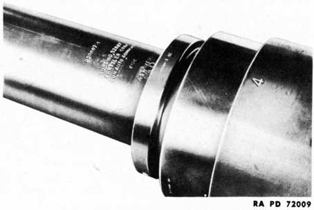
Figure 118 - Tube Serial Number
(3) Determining when replacements of parts is necessary because of ordinary wear or defects in parts.
74. VISUAL INSPECTION UPON RECEIPT.
a. Upon receipt of this materiel, it is the responsibility of the officer in charge to ascertain whether the materiel is complete and in sound operating condition. A record should be made of any missing parts and of any malfunctions, and any such conditions should be corrected as quickly as possible.
b. Attention should be given to small and minor parts, as these are the more likely to become lost and their lack may seriously affect the proper functioning of the materiel.
c. This visual inspection upon receipt should be followed as quickly as possible by a complete inspection which will disclose the functioning of the materiel (pars. 76 and 77).
75. SERIAL NUMBERS.
a. Three serial numbers are required for records concerning the components of this materiel. They are the tube serial number, the gun serial number, and the carriage serial number.
b. Tube Serial Number. The tube serial number is stamped in the top surface of the breech end of the tube (fig. 118).
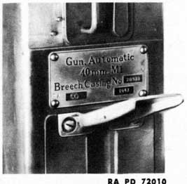
c. Gun Serial Number. The gun serial number is stamped on a metal plate mounted on top of the breech casing directly in front of the automatic loader (fig. 119).
157
Figure 119 - Gun Serial Number
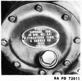
Figure 120 - Carriage Serial Number
d. Carriage Serial Number. The carriage serial number is stamped on a metal plate mounted on the elevating mechanism worm wheel cover on the left side of the carriage (fig. 120).
76. INSPECTION OF GUN.
a. The following instructions will be carefully observed by all concerned:
Parts To Be Inspected in Order of Inspection
Points To Observe
Gun as a unit.
Note general appearance. Test smoothness of operation of breech mechanism. Test operation of firing mechanism, first by cocking the gun and depressing rear firing pedal; then by cocking the gun and depressing forward firing pedal. Open and close top cover, side cover, and bottom cover; note fit and security with which they lock.
Barrel assembly.
Remove barrel assembly. Examine interrupted threads and recesses in breech face for scoring or other mutilation. Note the condition of the bore for wear on lands or deposits in grooves; erosion at origin of rifling. Examine barrel guide sleeve for burs, wear, or mutilations. See that barrel guide sleeve and
158
Parts To Be Inspected in Order of Inspection
Points To Observe
locking collar are properly positioned and that barrel guide sleeve locking set screw and friction disk are tightly screwed into place. Note condition of copper gasket at rear of flash hider. Examine condition of recuperator spring. Replace barrel assembly.
Breechblock.
Remove breechblock, inner cranks, and extractors. Inspect for wear, burs, or other mutilations. Note condition of impact surfaces on front face of breechblock. See that parts are clean and well lubricated. Be sure breechblock firing pin bushing locking pin is secure and flush with front face of breechblock. Measure protrusion of firing pin with striker protrusion gage. Replace extractors, breechblock, and inner cranks.
Recoil cylinder.
Check for proper amount of recoil liquid. Note recoil cylinder anchor bracket for its proper assembly (par. 86 f). Check setting of counterrecoil adjusting valve. Inspect for leaks.
Automatic loader.
Insert a clip of dummy ammunition in automatic loader and check for proper operation.
77. INSPECTION OF CARRIAGE.
a. The following instructions will be carefully observed by all concerned:
Carriage.
Note general appearance. Examine all covers. Note whether oil and grease fittings are clean and painted red, that a red ring has been painted around all oilholes, and that carriage is painted in accordance with regulations.
159
Parts To Be Inspected in Order of Inspection
Points To Observe
Note any gloss on finish or any unnecessarily bright metal that would affect camouflage value.
Compensating springs.
Lower carriage to ground. Examine action and effectiveness of locking handles and compensating springs. Test levelness of carriage in traverse (par. 67 g). While wheels are off ground, rotate to test for drag. After inspecting elevating and traversing mechanism, raise carriage.
Elevating mechanism.
Elevate and depress gun manually throughout full extent of travel. Note whether same effort is required to elevate and depress. Examine for excessive backlash. Check elevating arc for dirt, rust, wear, burs, and protective lubrication. Check lubrication in gear case. Be sure there is no leakage. Test elevation by remote control. Check oil gears for oil levels in oil gear, chain case, and clutch housing; creep and dither. Creep should be as near zero as possible; dither should be noticeable to touch.
Traversing mechanism.
Traverse by hand, left and right, 360 degrees to check smoothness of action. Examine for excessive backlash. Check lubrication in gear cases. Be sure there is no leakage. Test traverse by remote control. Check oil gears for oil levels, creep, and dither. Test operation of power synchronizing (slewing) handle.
Top carriage and carriage frame.
Examine for breaks and cracks, and for loose attachment screws and nuts. Determine whether outrigger hinges and leveling jacks are lubricated adequately and operate and lock properly.
160
Parts To Be Inspected in Order of Inspection
Points To Observe
Examine stake and other accessory mountings on frame, outriggers, and loading platform. See that frame and swivel body have been drained. Inspect lower surfaces of carriage for rust.
Drawbar and gun stay.
Look for undue wear on lunette. Examine drawbar connections and pins. Check connections and operation of upper plungers of gun stay.
Brakes.
Tow carriage and test effectiveness of brakes by making several stops. Test action of hand brakes. Travel slowly and pull safety switch chain; carriage should stop suddenly.
Wheels and tires.
Check for any loose or missing nuts. Check tires for correct pressure, 45 pounds per square inch. Note condition of tires and whether treads are taking wear evenly.
Lights.
Test service stop lights and taillights. Turn blackout light switch and test blackout stop lights and taillights. Check condition of reflectors.
Section IX DISASSEMBLY AND ASSEMBLY
78. GENERAL.
a. Wear, breakage, cleaning, and inspection make necessary the occasional disassembly and assembly of various parts of the weapon. This work comes under two headings, that which can be performed by the using arm personnel, and that which must be performed by ordnance maintenance personnel.
b. The using arm personnel may, in general, do such dismounting,
161
replacing, repairing, and installing of parts as may be required for cleaning, lubrication, inspection, adjustment, and the installation of such spare parts as are regularly issued to the using arms, or which may be installed with the tools and equipment available to the using arm personnel. All work should be done in the manner prescribed and with the proper tools. Any difficulty which cannot be overcome must be brought to the attention of ordnance maintenance personnel.
c. The using arm personnel will not attempt unauthorized disassembly of any unit of the weapon nor any filing of parts other than specified in this manual, except by order of the commanding officer.
d. Avoid the use of wrenches that do not fit snugly on the parts or of screwdrivers that do not fit the slots in screws properly. The poor fitting of these tools will not only damage the corners of nuts and bolt heads and the slots of screws, but may also damage the tools.
e. Before attempting to put together the larger assemblies which compose the weapon, the assembly of subassemblies should be completed. In this work, all bearings, sliding surfaces, threads, and enclosed portions of parts should be cleaned and oiled for lubrication as well as for the prevention of rust. Care must be exercised to exclude dust, moisture, and other foreign matter,
f. A steel hammer, chisel, or screwdriver should not be used to drive directly against any part of the gun or machined part of the carriage. A copper or wooden mallet, or a copper-, rawhide-, or plastic-faced hammer should be used, or a brass or copper drift or a hardwood block should be interposed between the blow and the part to be struck.
79. BARREL ASSEMBLY REMOVAL AND INSTALLATION.
a. The removal and replacement of the barrel assembly is a using arms operation. Barrel assemblies of the 40-mm Automatic Gun M1 are interchangeable in the breech ring assemblies of all 40-mm Automatic Guns M1.
b. The barrel assembly may be removed independently, or it may be removed as part of a sequence of operations including removal of the automatic loader and breech ring. If the automatic loader and breech ring are to be removed, a slightly different series of operations must be performed than when the barrel assembly is to be removed independently.
c. Barrel Assembly Removal (When Breech Ring Is Not To Be Removed).
(1) Place the gun in horizontal position. Secure the breech casing to the gun stay. Open the breech by means of the hand operating lever. Insert the breechblock locking pin in its appropriate holes in the breech casing and breech ring (fig. 121).
162
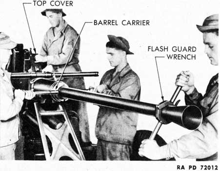
Figure 121-Barrel Assembly-Unlocking
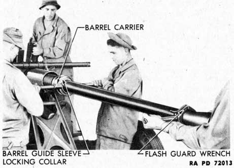
(2) Assemble the flash guard wrench on its seat on the muzzle end of the tube. Be sure that the hinged portion of the wrench is placed at the top. When assembled in this position, the hinged portion of the wrench will be beneath the tube after the tube has been rotated one-half turn, and there will be less likelihood of the wrench being broken when the tube is being carried.
(3) Place the barrel carrier under the tube, fitting the lug on the carrier in the groove on the barrel guide sleeve locking collar (fig. 121). Place one man on each handle of the barrel carrier, as these men must support the greater portion of the weight of the barrel assembly when it is removed from the breech casing. One man can handle the flash guard wrench and be in a better position to maneuver it properly than if two men manipulate it.
CAUTION: In carrying the barrel assembly, keep it on an even keel. If the muzzle end is raised, there is a possibility that the barrel assembly will become detached from the barrel carrier, permitting the breech of the barrel to strike the ground.
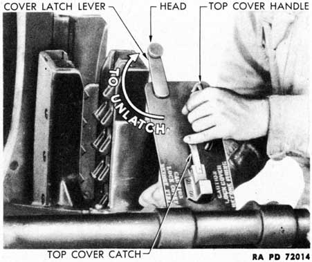
(4) Open the top cover on the breech casing by lifting the cover latch lever head and rotating the cover latch lever (fig. 122) clockwise, depressing the top cover catch, and lifting the top cover by its handle. The cover will lock automatically in upright position. Opening the top cover will lift and release the breech ring barrel catch.
(5) Rotate the tube one-half turn counterclockwise (fig. 121). This will unlock the interrupted threads holding the tube in the breech ring.
163
Figure 122-Top Cover-Opened
Figure 123-Barrel Assembly-Removal
(6) Withdraw the barrel assembly straight forward from the breech casing (fig. 123), with the men supporting the barrel carrier exercising caution that the interrupted threads on the tube do not come in contact with the breech casing as the barrel guide sleeve slides from the casing.
CAUTION: Do not attempt to remove the barrel assembly unless
164
Figure 124-Side Cover-Opening With Key
the breech is open or the breechblock has been removed from the breech ring. To do so will damage the extractors and produce burs in the extractor grooves in the breech end of the barrel.
d. Barrel Assembly Installation (When Breech Ring Has Not Been Removed).
(1) Check to see that the top cover on the breech casing is in the open position. Check to see that breechblock is open.
(2) Assemble the flash guard wrench on its seat with the hinged portion of the wrench under the tube. Place the barrel carrier under the tube, catching its lug in the groove of the collar.
(3) Lift the barrel assembly and insert the breech end of the tube in the front opening of the breech casing, carefully sliding it into the casing to prevent damage to the threads. By means of the flash guard wrench, rotate the tube one-half turn clockwise.
(4) Release the top cover catch, close the top cover, and lock it with the cover latch lever, locking the barrel assembly in the breech ring with the breech ring barrel catch. Remove the wrench and carrier.
80. BREECHBLOCK, CLOSING SPRING, AND EXTRACTOR REMOVAL AND INSTALLATION.
NOTE: The breechblock and closing spring assemblies may be removed without dismantling other parts of the weapon. If, however, the breech ring is to be removed, the breechblock and closing spring
165
Figure 125-Closing Spring Assembly Removal
Figure 126-Breechblock and Inner Cranks Removal
assemblies must be removed before the barrel assembly is taken from the weapon.
a. Breechblock and Closing Spring Assemblies Removal.
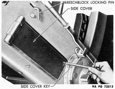
(1) Open the side cover by inserting the side cover key (fig. 124), pressing the key inwardly, and turning it counterclockwise. Tie back the side cover with a piece of cord to retain it in open position.
(2) Close the breech. Elevate the gun to about 45 degrees. Release the bottom cover by rotating the cover latch lever and remove this cover by disengaging its rear end from the breech casing.
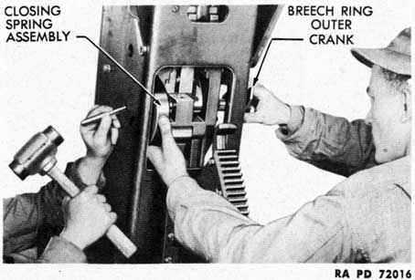
(3) Through the smaller hole in the right side of the breech casing, tap the breech ring outer crankshaft to the left about 2 inches, sufficient to permit the removal of the breech ring closing spring assembly. Use a brass drift. Remove the closing spring assembly (fig. 125).
166
Figure 127-Extractor Removal From Assembled Gun
Figure 128-Breechblock and Inner Cranks Held for Assembly
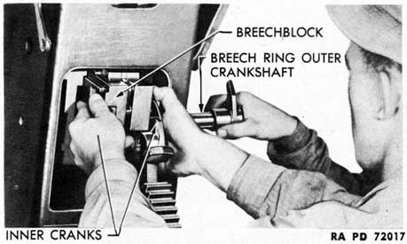
(4) Support the breechblock and right and left inner cranks, and pull the breech ring outer crank and crankshaft all the way out. Guide the breechblock assembly with the inner cranks out of the breech ring and through the opening in the bottom of the breech casing (fig. 126).
b. Extractors Removal.
NOTE: The cartridge extractors can be removed and replaced without removing the breech ring from the breech casing, or they can
167
Figure 129-Breechblock and Inner Cranks-Installation
be removed after the breech ring has been taken from the casing (par. 83 a). To remove the extractors from the assembled gun, the breechblock must first be removed (subpar. a, above).
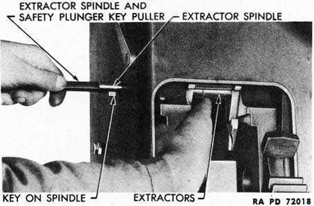
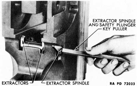
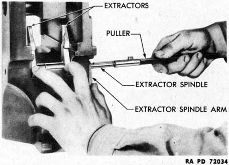
(1) Through the larger of the two holes in the right side of the breech casing, screw the extractor spindle and safety plunger key puller into the threaded hole in the end of the extractor spindle.
(2) Reach through the bottom opening in the breech casing and support the extractors to keep them from falling out of the weapon after they have been released. Rotate the extractor spindle by means of the puller until the key on the spindle is mated with the keyway in the extractors. Withdraw the extractor spindle by means of the puller (fig. 127). Withdraw the extractors.
c. Extractor Installation. Screw the puller into the threaded end of the extractor spindle. Assemble the two extractors together. Place and hold the extractors in position in the breech ring. Insert the extractor spindle through the larger hole in the right side of the breech casing and through the breech ring and extractors, mating the key and keyway. Unscrew the puller.
d. Breechblock and Closing Spring Assemblies Installation.
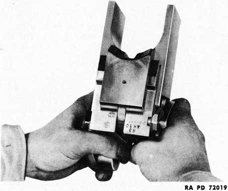
(1) Insert the lugs of the left and right breech ring inner cranks in the grooves in the sides of the breechblock. Hold these parts in the manner illustrated in figure 128. Holding the parts in this manner will automatically cock the percussion mechanism.
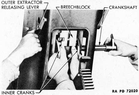
(2) With the bottom cover removed, insert the breechblock and inner cranks into the bottom of the breech ring until further inward movement is stopped by the extractors. Press the extractor release lever (fig. 129) and push the breechblock into the breech ring as far
168
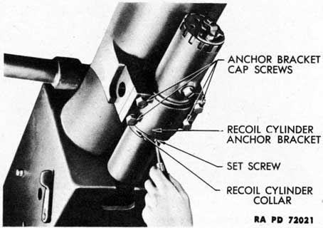
Figure 130-Recoil Cylinder Collar-Loosening Set Screw
as it will go. Insert the breech ring outer crankshaft sufficiently to hold the breechblock in place.
(3) Insert the breech ring closing spring assembly and drive the crankshaft to its fully assembled position. Install the bottom cover.
81. FIELD STRIP DISASSEMBLY.
a. The field stripping of the gun involves the removal of the recoil cylinder, breech mechanism, barrel assembly, automatic loader and breech ring.
b. Before proceeding to disassemble the weapon by the series of operations required for the field strip, the breechblock must be in closed position and the rammer spring must be released. To release the rammer spring, move the outer safety lever from "SAFE" to "AUTO FIRE," move the feed control thumb lever to the right, and step on the firing pedal; then return the levers to their original positions.
c. Recoil Cylinder Removal.
NOTE: It is necessary that the recoil cylinder be removed to permit the removal of the breech ring from the breech casing.
(1) Elevate the gun to approximately 45 degrees. Loosen the set screw in the recoil cylinder collar (fig. 130). Back the collar from the recoil cylinder anchor bracket. If the recoil cylinder wrench is available, it should be used to remove the collar; otherwise, the collar should be loosened by being rotated with a brass drift and hammer.
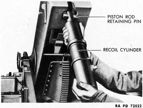
(2) Support the cylinder and remove the four anchor bracket cap
169
Figure 131-Recoil Cylinder-Removal
screws. Remove the anchor bracket. Lower the recoil cylinder until it is at approximately right angles to the gun. Disengage the recoil cylinder piston rod retaining pin from the lugs of the breech ring (fig. 131), and remove the recoil cylinder.
d. Breech Mechanism Removal. Remove the breechblock, inner cranks, and closing spring case (subpar. a, above). The extractors need not be removed at this time. Detail strip the breechblock (par. 82). Disassemble the breechblock closing spring (par. 84).
e. Barrel Assembly Removal. Follow the instructions given in paragraph 79 c. The hand operating lever must not be moved as the breechblock has already been removed from the breech ring.
CAUTION: Be sure that the top cover remains in locked open position or that the breech ring locking pin is in its place in the holes in the breech casing and breech ring. These devices prevent the breech ring and automatic loading tray from moving to the rear after the barrel assembly has been removed.
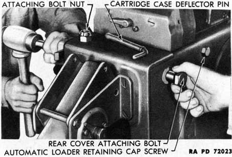
f. Rear Cover Release. Remove the cartridge case deflector pin and press down the lower end of the deflector. Remove the nut from the rear cover attaching bolt. Drive out the attaching bolt (fig. 132). Lower the rear cover, being careful not to let it fall back violently as the bolt is removed.
g. Automatic Loader Removal.
NOTE: The automatic loader assembly may be removed independently of other parts of the weapon. The rear cover must first be lowered (subpar. f, above).
170
Figure 132-Rear Cover-Release
Figure 133-Loading Tray Attaching Bolt-Removal
(1) Place the gun at zero elevation. Remove the automatic
loader retaining cap screws from both sides of the breech casing (fig. 132).
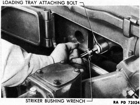
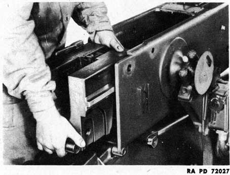
(2) With the striker bushing wrench, remove the loading tray attaching bolt (fig. 133). To remove this bolt, it must be pressed inwardly with the wrench and turned 90 degrees in either direction.
(3) Be sure that the feed control thumb lever is in its left position.
171
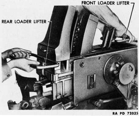
Figure 134-Loader Lifters-Attachment
This is necessary in order to raise the right rammer check lever plunger and protect it from damage.
(4) Slide the loading tray backward to the rear edge of the breech casing to raise the center rammer catch lever plunger and protect it from damage when the automatic loader assembly is removed from the breech casing.
(5) Slide the entire automatic loader assembly approximately 5 inches to the rear to permit the attachment of the front and rear loader lifters. Attach the lifters (fig. 134).
(6) With a man grasping each of the loader lifters, lift the automatic loader to clear any obstruction, sliding it backward on its rails out of the breech casing through the opening made by the lowering of the rear cover.
CAUTION: When placing the automatic loader on a flat surface after its removal from the breech casing, great care must be taken to avoid damage to the feed roller catch release spindles. A slight tilting movement at the time of contact may result in bending the spindles.
(7) LOADING TRAY REMOVAL. After the automatic loader has been removed from the breech casing, slide the loading tray out the front end of the loader. Remove the loose loader feed rod rollers from the lower ends of the feed rods to prevent their being lost.
(8) LOADING TRAY INSTALLATION.
(a) Install the loader feed rod rollers on their pins in the lower ends of the feed rods. Insert the loading tray in the front end of the
172
Figure 135-Breech Ring-Removal
loader and push it to the rear, making sure that the loader feed rod rollers are in their grooves in the sides of the loading tray. If, by accident or carelessness, the tray is inserted with the rollers on top of the grooves, the loader will be badly damaged when the weapon is fired.
(b) Do not push the loading tray too far to the rear of the loader. This will cause the catch and check levers to catch under the rammer shoe and the loading tray cannot be pulled forward for attachment to the breech ring.
(c) If the loading tray should be pushed too far, it may be disengaged in the following manner: Release the feed control check lever by rotating the feed control thumb lever. Release the firing mechanism check lever by rotating the rammer control spindle arm. Release the rammer catch lever by pressing the rammer release lever with a screwdriver and pulling the tray forward.
h. Breech Ring Removal.
NOTE: The recoil cylinder, breechblock and closing spring, barrel assembly, and automatic loader must be removed before the breech ring can be removed.
(1) Close the top cover to release the breech ring and the breech ring barrel catch. Remove the breechblock locking pin from its holes in the breech casing and breech ring, and place it in its bracket.
(2) Slide the breech ring assembly backward along its guideways and lift it out of the breech casing (fig. 135). Do not let the breech ring assembly drop as it comes to the end of the guideways.
(3) Detail strip the breech ring (par. 83).
173
Figure 136-Breechblock Firing Pin Spring Cover-Removal
Figure 137-Breechblock Firing Pin and Spring-Removal
82. BREECHBLOCK DISASSEMBLY AND ASSEMBLY.
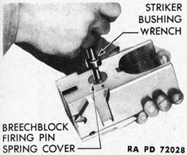
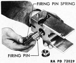
a. Firing Pin Removal. With the striker bushing wrench, remove the breechblock firing pin spring cover by pressing the wrench inwardly and turning it 90 degrees in either direction (fig. 136). Remove the breechblock firing pin spring and the firing pin (fig. 137).
b. Firing Pin Installation. Place the firing pin spring in the cup of the firing pin. Insert the spring and firing pin in the bore of the breechblock (fig. 137). With the striker bushing wrench in the opening in the back of breechblock firing pin spring cover, press the cover into the bore of the breechblock and turn the cover 90 degrees to match the outer point of the diamond on the cover with the arrow on the rear face of the breechblock (fig. 136).
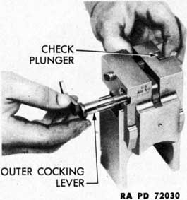
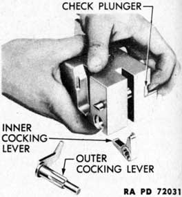
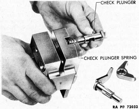
c. Inner Cocking Lever and Check Plunger Removal.
(1) Press the check plunger inwardly and withdraw the outer cocking lever (fig. 138). Press the check plunger, turn the breechblock so that the front face is downward, and shake out the inner cocking lever (fig. 139). Withdraw the check plunger and check plunger spring (fig. 140).
d. Check Plunger and Inner Cocking Lever Installation. Insert the check plunger spring and check plunger in their bore in the breechblock (fig. 132). While holding the check plunger in, insert the inner cocking lever, fitting the end which is slotted into the slot in the check plunger. Press the check plunger in and insert the outer cocking lever, fitting the splined portion of the outer cocking lever shaft into the splineways in the hub of the inner cocking lever.
83. BREECH RING DISASSEMBLY AND ASSEMBLY.
a. Extractor Removal. Screw the extractor spindle and safety plunger key puller into the threaded hole in the end of the extractor spindle (fig. 141). Holding the extractors upright and the extractor
174
Figure 138-Outer Cocking
Lever-Withdrawal
Figure 139-Inner Cocking
Lever-Removal
Figure 140-Check Plunger and Spring-Removal
spindle arm down, withdraw the extractor spindle (fig. 142). Remove the extractor spindle arm and the extractors from the breech ring.
h. Extractor Installation. Place the extractor spindle arm in position. Assemble the two extractors together and lay them in position in the breech ring. Aline the keyways in the extractors and the key on the spindle arm by holding them in the manner shown in figure 142, and insert the extractor spindle.
175
Figure 141-Puller Assembled to Extractor Spindle
Figure 142-Extractor Spindle Installation
NOTE: The extractors may be removed from the breech ring without removing the breech ring from the weapon. This operation is described in paragraph 80 b.
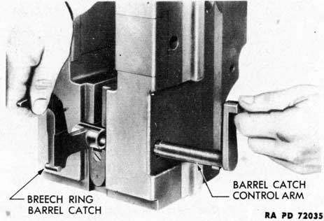
c. Breech Ring Barrel Catch Removal. Raise the breech ring barrel catch until the shaft which extends from the bushing is at right angles to the top surface of the breech ring. Withdraw the breech ring barrel catch control arm (fig. 143). In doing this, the key on the shaft of the arm must be mated with the keyway in the breech ring. Remove the barrel catch.
176
Figure 143-Breech Ring Barrel Catch-Removal
Figure 144-Closing Spring
Assembly on Bracket
Figure 145-Closing Spring
Cover-Release
d. Breech Ring Barrel Catch Installation. Place the bushing of the barrel catch in the recess in the top of the breech ring, holding the barrel catch at right angles to the top surface of the breech ring. Insert the shaft of the barrel catch control arm into the breech ring through the bushing of the barrel catch.
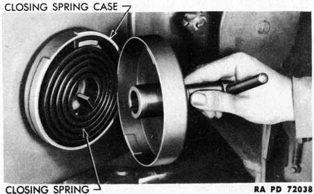
84. BREECH RING CLOSING SPRING DISASSEMBLY AND ASSEMBLY.
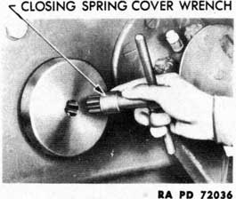
a. Disassembly. Place the assembled breech ring closing spring case on the breech ring closing spring case bracket (fig. 144). This bracket is located on the right side of the breech casing near the rear end. Insert the closing spring cover wrench in the hole in the center of the case, engaging the protruding end of the closing spring
177
Figure 146-Closing Spring, Case, and Cover-Disassembled
Figure 147-Breech Ring Safety Plunger-Disassembled
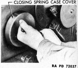
with the pronged end of the wrench. Force the closing spring case cover inwardly to disengage the bayonet connection on the inside of the rim of the cover and on the outside of the rim of the case (fig. 145). Permit the cover to rotate counterclockwise under the action of the spring, taking care to prevent the tension from being released too violently. Remove the case cover and wrench (fig. 146). Remove the closing spring from the case.
b. Assembly. With the closing spring case on the closing spring case bracket, place the closing spring in the case (fig. 146). Fit the closing spring case cover over the case and spring. Insert the closing
178
Figure 148-Breech Ring Crankshaft Collar-Disassembled
spring cover wrench in the hole in the center of the case. Turn the wrench clockwise to wind the closing spring and to lock the bayonet connection of the case and cover. There will be an audible click as the case locks in position. Remove the closing spring assembly from the bracket.
85. BREECH RING BROKEN OR DEFORMED PARTS REPLACEMENT.
a. General. These instructions are given for the removal and replacement of parts of the breech ring which may become broken or deformed and of springs which may become broken or weak.
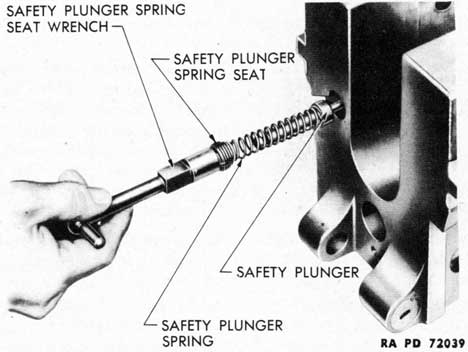
b. Breech Ring Safety Plunger and Spring. Unscrew the safety plunger spring seat by inserting the teats of the safety plunger and spring seat wrench in the slots of the seat and turning the seat counterclockwise. This seat is staked in position by having some of the metal of the breech ring driven into its slots. It must be worked out of its threaded bore carefully with short counterclockwise and clockwise twists to prevent damage to the seat or wrench. Remove the seat, safety plunger spring, and safety plunger (fig. 147). Replace defective parts with new ones, install, and stake.
NOTE: This operation should be performed only by qualified battery mechanic.
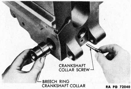
c. Breech Ring Crankshaft Collar. Unscrew and withdraw the breech ring crankshaft collar screw. Slide the breech ring crankshaft collar out of place (fig. 148). Replace worn or damaged collar with a new one and install parts.
179
Figure 149-Loading Tray Bolt
Spring-Disassembled
Figure 150-Breech Ring
Barrel Abutment-
Disassembled
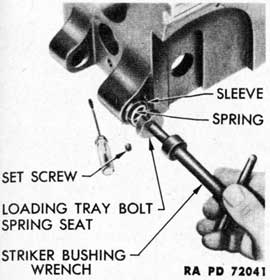
d. Loading Tray Bolt Spring. Remove the headless set screw from the edge of the loading tray bolt spring seat (fig. 149). Unscrew the seat, using the striker bushing wrench. Remove the loading tray bolt spring and sleeve. Replace damaged parts with new ones and install.
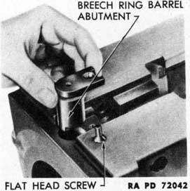
e. Breech Ring Barrel Abutment. Remove the flat-head screw which holds the breech ring barrel abutment in place in the top of the front end of the breech ring (fig. 150). Remove the abutment. Replace the damaged abutment with a new one and install.
86. FIELD STRIP ASSEMBLY.
a. Breech Ring Installation. Place the breech ring assembly in its guideways at the open rear end of the breech casing. With the top cover closed, slide the breech ring forward as far as it will go, fitting the lugs on the sides of the breech ring barrel catch into the slot on the under side of the top cover. Open the top cover and insert the breechblock locking pin into its holes in the breech casing and breech ring to keep the breech ring from sliding backward in the casing.
b. Automatic Loader Installation. With the loading tray installed in the loader (par. 81 g (8)), attach the front and rear loader lifters to the automatic loader. Lift the automatic loader and carefully place the front ends of the guides in the guideways of the breech casing. Slide the automatic loader forward until it is supported by the guideways. Remove lifters and slide the automatic loader forward until the loading tray attaching bolt can be inserted and locked with its bayonet connection.
c. Rear Cover Attachment. Raise the rear cover. Tap in the
180
rear cover attaching bolt and replace the nut and cotter pin. Raise the lower end of the cartridge case deflector and insert the cartridge case deflector pin. Screw in automatic loader retaining screws.
d. Barrel Assembly Installation. Follow the instructions given in paragraph 79 d.
e. Breech Mechanism Installation. Install extractors (par. 80 c), if they have not already been installed. Elevate the gun to 45 degrees. Withdraw the breechblock locking pin. Install the breechblock, inner cranks, and breech ring closing spring case (par. 80 d).
f. Recoil Cylinder Installation. Holding the recoil cylinder at right angles to the bottom of the breech casing and with the flat surface on the recoil cylinder flange upward, engage the recoil cylinder piston rod retaining pin in the lugs on the lower front end of the breech ring. Raise the recoil cylinder and secure it in place with the recoil cylinder anchor bracket by screwing in the four anchor bracket cap screws. Rotate the recoil cylinder collar until it bears against the side of the bracket. Lock the collar with its set screw.
NOTE: Recoil cylinder anchor bracket must be correctly mounted, or damage to recoil mechanism will result. Anchor brackets must be cleaned so numbers on casting will show. In installing the anchor bracket, the numbers on the anchor bracket must be matched with those on the breech casing.
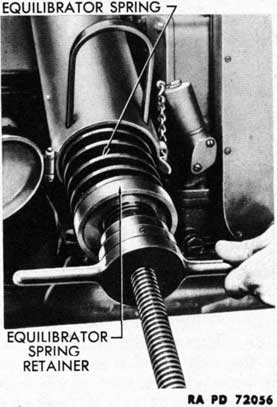
87. EQUILIBRATOR DISASSEMBLY AND ASSEMBLY.
a. Disassembly.
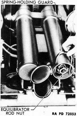
(1) Open the equilibrator case cover and insert the spring holding U-bar (fig. 151).
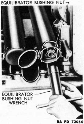
(2) Remove the equilibrator rod jam nut and bushing nut with equilibrator rod bushing nut wrench (fig. 152). At this point, the equilibrator springs will have expanded to the extent that the equilibrator spring retainer will be forced against the U-bar.
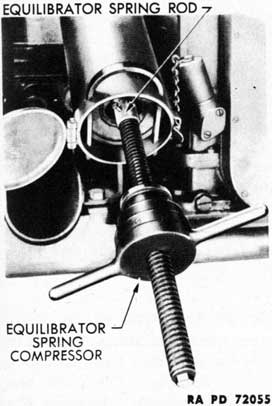
(3) Attach the equilibrator spring compressor to the end of the equilibrator spring rod (fig. 153). Screw the equilibrator spring compressor sufficiently to force the equilibrator spring retainer away from the U-bar so that the U-bar may be removed. Remove the U-bar.
(4) Unscrew the spring compressor, relieving the compression on the equilibrator springs (fig. 154). When the compression has been entirely relieved, disassemble the spring compressor from the equilibrator rod. Remove the retainer, springs, and separators from the equilibrator case.
b. Assembly.
(1) Remove the handle from the equilibrator spring compressor.
181
Figure 151-Spring-holding
U-bar-Insertion
Figure 152-Equilibrator Rod
Bushing Nut-Removal
Figure 153-Equilibrator Spring
Compressor-In Place
Figure 154-Equilibrator Spring
Rod-Removal
182
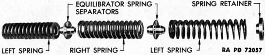
Figure 155-Equilibrator Springs, Separators, and Retainer
Attach the threaded shaft of the compressor to the end of the equilibrator spring rod.
(2) Place the equilibrator springs, separators, and retainer on the threaded shaft of the compressor and the equilibrator spring rod in the following order: one left spring; one separator; one right spring; one separator; one left spring; one retainer (fig. 155).
(3) Screw on the compressor handle and compress the springs sufficiently to permit the U-bar to be installed. Remove the compressor. Screw on the equilibrator rod bushing nut. Remove the U-bar.
(4) After both equilibrators have been assembled to this point, test the amount of effort required to elevate and depress the gun. If the effort to depress the gun is more than that required to elevate, turn out the bushing nut; if the effort to elevate is more than that to depress the gun, turn in the bushing nut. Adjust both assemblies exactly alike.
(5) When the adjustment is completed, lock both bushing nuts in position with the equilibrator rod jam nuts. Close end covers.
88. WHEEL, HUB, AND BRAKE DRUM DISASSEMBLY AND ASSEMBLY.
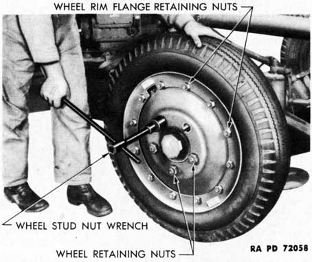
a. Wheel Removal. Lift the wheels clear of the ground by raising the carriage with the leveling jacks. Remove the wheel retaining nuts with the wheel stud nut wrench (fig. 156). Wheels on the right side of the carriage have right-hand thread studs and nuts; wheels on the left side have left-hand thread studs and nuts. Remove the wheel and tire assembly.
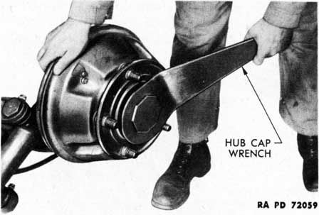
b. Hub and Brake. Drum Removal.
(1) Remove the hub cap with the hub cap wrench (fig. 157).
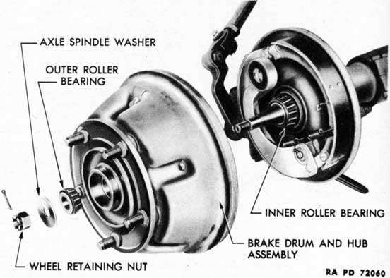
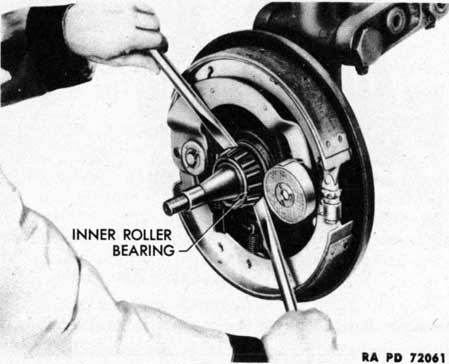
(2) Remove the cotter pin from the wheel retaining castle nut on the axle spindle (fig. 158). Unscrew the castle nut. Remove the axle spindle washer and outer roller bearing. Dismount the brake drum and hub assembly from the axle spindle. Remove the inner roller bearing (fig. 159).
CAUTION: Do not allow grease or oil to touch the magnet or
183
Figure 156 - Wheels - Removal
Figure 157 - Hub Cap - Removal
brake linings. Do not touch the magnet or brake linings with oily hands.
c. Hub and Brake Drum Installation.
(1) Clean drum, armature, wheel bearings, nut, washer, hub cap, hub, and axle spindle of old grease. Wash with SOLVENT, dry-cleaning.
CAUTION: Do not allow any grease or solvent to touch the brake
184
Figure 158 - Wheel Hub Parts - Disassembled View
Figure 159 - Inner Roller Bearing - Removal
185
lining or magnet. The brake drum and armature must be clean and free of grease.
(2) If the brake magnet and armature show signs of wear, or if the brake lining or magnet are glazed, the matter should be brought to the attention of the ordnance maintenance personnel for correction.
(3) Be sure that the solvent is dried off the wheel bearings, then repack the bearings with grease in the prescribed manner.
(4) Install the grease-packed inner wheel bearing on the spindle. Install the hub and drum assembly. Install the grease-packed outer wheel bearing in the hub. Slide the axle spindle washer on the spindle.
d. Wheel Bearing Adjustment. Screw on the wheel retaining castle nut. Tighten the nut and rotate the brake drum. Tighten until a drag is felt when the hub and drum assembly is rotated. Then back off the nut until the hub and drum assembly rotate freely; one-sixth turn is usually enough. Fit the cotter pin in the wheel retaining castle nut. Install the hub cap.
e. Wheel Installation. Install the wheel and wheel retaining nuts. Tighten the nuts in rotation to center the studs in their holes in the wheel, using the wheel stud nut wrench. Tighten the nuts securely.
89. TIRE REMOVAL AND INSTALLATION.
NOTE: For maintenance and care of pneumatic tires and rubber treads, refer to TM 31-200.
a. Divided Rim Type Wheels.
(1) REMOVAL.
(a) Remove the wheel from the carriage (par. 88 a). Remove the valve cap and valve core.
CAUTION: Tires must be completely deflated before any attempt is made to remove wheel rim flange retaining nuts. An inflated tire may blow a partially removed flange off the wheel and cause serious injury to personnel.
(b) Remove all of the flange retaining nuts. Drive a tire iron between the flange and tire; then lift off the flange.
(c) Turn over the wheel and tire, loosen the wheel from the tire by prying with a tire iron, and lift the wheel out of the tire.
(d) To remove the beadlock from combat tires, inflate the tube until the tire beads spread away from the flanged blocks. If the bead-lock flange blocks stick to the tire, pry them loose with a tire iron. Pull out the beadlock.
(e) Deflate the tube. Remove the flap and tube.
(2) INSTALLATION.
(a) Be sure that all dirt and rust have been removed from the tire and that the tube is clean; then insert the tube and flap. The
186
flap must be smooth; folds or wrinkles will result in tube failure.
(b) On combat tires, inflate the tube to spread the tire beads to install the beadlock. Place the beadlock over the valve. Push the beadlock down between the beads. Fold the flexible band of the beadlock and insert it between the tire beads. Deflate the tube, making sure that flanged blocks of the beadlock are centered between the beads.
(c) Place the tire assembly on the wheel, centering the valve in the valve slot. Install the wheel rim flange and tighten four nuts equally spaced around the wheel; this is to seat the flange evenly. Then install the remaining nuts and tighten all nuts.
(d) Install the valve core and inflate the tire to 45 pounds per square inch. Screw on the valve cap tightly by hand.
b. Flat Base Rim Type Wheels.
(1) REMOVAL.
(a) Remove the wheel from the carriage (par. 88 a). Remove the valve cap and valve core.
CAUTION: Make sure the tire is completely deflated.
(b) Using two tire irons, pry the two ends of the locking ring apart, and at the same time, pry the slotted end of the ring out of the rim well. With the slotted end of the ring free of the rim, continue to pry or pull the rest of the ring out of the rim well, being careful not to bend or spring the ring out of round. (To remove the beadlock from combat tires, see par. 89 a (1) (d).)
(c) Turn the wheel and tire assembly over and block up under the wheel. Pry the tire bead loose from the wheel, using a tire iron and hammer if necessary. Force the tire down off the wheel. Lift off the wheel assembly.
(d) Remove the tire inner liner or flap. Spread the tire beads apart and work the tube out of the tire casing.
(2) INSTALLATION.
(a) Be sure that all dirt and rust have been removed from the tire and that the tube is clean. A small amount of tire talc applied to the inside of the tire is recommended. Insert the tube and flap, working the edges of the flap under the tire beads. The flap must be smooth; folds or wrinkles will result in tube failure. (To install tubes in compact tires, see par. a (2) (b).)
(b) Insert the plain end of the locking ring in the rim well. Pry down on the ring about one-third of the distance around the ring from the plain end. At the same time, hammer more of the ring into the rim well. Spread the locking ring by prying the two ends apart, and while doing this, hammer the ring into the rim well throughout its entire length. Make sure the ring is securely seated in the rim well before inflating the tire.
187
(c) Install the valve core and inflate the tire to the recommended pressure, 45 pounds per square inch. Install the wheel (par. 88 e).
CAUTION: Tap the locking ring during the initial inflation of the tire to seat it firmly in the rim well. Stand aside while inflating the tire to avoid personal injury in case the locking ring is not properly seated in the rim well and flies off the wheel.