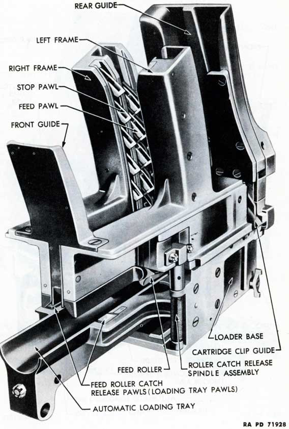
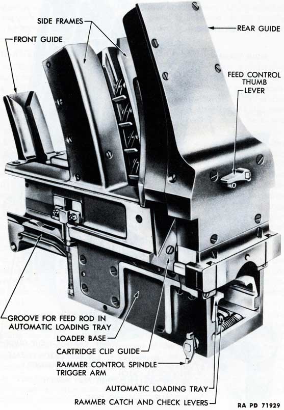
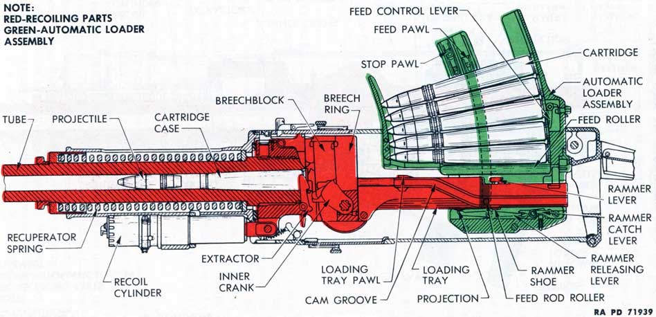
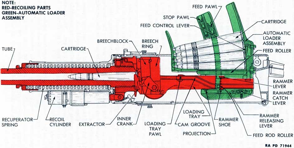
a. The automatic loader (figs. 28 and 29) is both a cartridge magazine and a loading device. Cartridges, in clips of four, are inserted in the top of the loader. They are fed singly to the automatic loading tray, the clips being removed automatically in the process. The cartridges are rammed into the chamber of the gun, tripping the extractors and permitting the breechblock to be raised after which the gun fires automatically.
b. Cartridges may be loaded manually or automatically. After the mechanism has been manually prepared for automatic loading, the feed mechanism of the loader feeds the loading tray with a continuous supply of cartridges. Provisions are made to insure that only one cartridge is fed onto the loading tray at a time, that automatic loading and firing can be stopped when only one cartridge remains in the feed guides and one cartridge on the loading tray (to eliminate the necessity of manual reloading), that the rammer cannot be released until the gun reaches the end of counterrecoil, and that the rammer can be latched out of action to prevent accidental discharge of the weapon.
c. The front and rear cartridge guides and the upper part of the feed mechanism protrude from the top of the breech casing and are covered by the automatic loader hood when the gun is not in action. All other parts of the loader are contained within the breech casing (fig. 5).
d. All parts of the loader with the exception of the loading tray and rammer remain in a fixed position in the breech casing. The loading tray is bolted to the rear end of the breech ring and recoils and counterrecoils with it. The motion of the loading tray is the main source of energy for the operation of the feed mechanism. The rammer moves independently of the loading tray to ram the cartridges.
e. The principal mechanisms of the automatic loader are the feed mechanism, automatic loading tray, cartridge rammer assembly, and automatic loader control mechanism.
14. AUTOMATIC LOADER FEED MECHANISM.
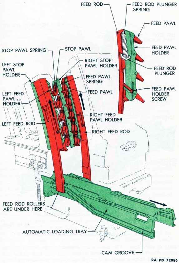
a. The feed mechanism (figs. 30 and 31) comprises those parts of the automatic loader which feed the loading tray with a continuous
45
Figure 28-Automatic Loader-Front View
46
Figure 29-Automatic Loader-Rear View
47
Figure 30-Feed Mechanism-Raised Position
48
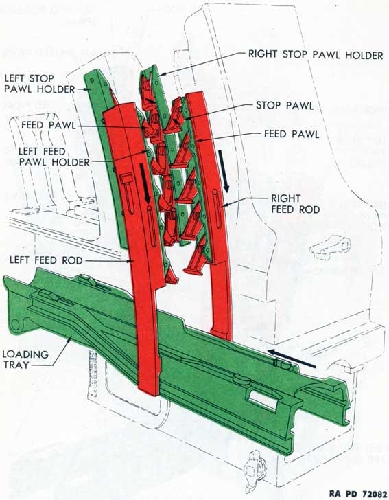
Figure 31-Feed Mechanism-Lowered Position
supply of cartridges. The mechanism consists of the front and rear guides, side frames, feed rods and rollers, feed and stop pawls and holders, feed rollers, catches, and plungers, and the cartridge clip release arrangement.
b. Feed and Stop Pawls.
(1) The feed and stop pawls and holders are housed in the side
49
Figure 32-Feed Rollers-Engaged
frames. The feed pawls are operated by the feed rods which are raised and lowered by the feed rod rollers moving in the cam grooves in the sides of the loading tray as the loading tray recoils and counter-recoils. The feed pawls move all cartridges in the loader downward each time a round is fired. The stop pawls, which are retained in stationary holders, prevent the cartridges from moving upward during recoil.
(2) During recoil, the feed rod rollers moving in the cam grooves in the sides of the loading tray raise the feed rods. The feed rods carry the feed pawl holders and pawls upward, the pawls riding against the sides of the cartridges in the loader on the upward movement. The stop pawls are forced outwardly from their holders by their torsion springs and prevent the cartridges from being raised as the feed pawls move upward.
(3) The feed rods draw the feed pawls downward in counterrecoil. The feed pawls, forced outwardly from their holders by their torsion springs, engage the cartridges and force them downward. The stop pawls are forced into their holders by the cartridges, permitting a cartridge to be fed onto the loading tray.
(4) Springs and plungers are provided on the tops of the feed rods
50
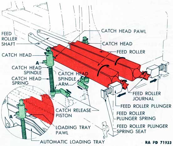
Figure 33-Feed Rollers-Released
to protect the mechanism in the case of a jammed cartridge. Should a cartridge jam during the downward movement, the compression of these springs permits the feed pawl holders to remain in the "up" position.
c. Feed Rollers.
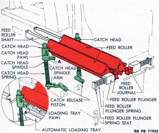
(1) The feed rollers (red in figs. 32 and 33) are metal prisms with four convex sides. They are located in the loader under the feed and stop pawl assemblies and over the loading tray. They are mounted to rotate in opposite directions. Their purpose is to insure that only one cartridge is fed onto the loading tray at a time.
(2) The feed rollers are revolved by the cartridge as it is forced down onto the loading tray. Their movement is controlled by the feed roller catch and plunger mechanisms.
d. Feed Roller Catch and Feed Roller Plunger Mechanisms.
(1) The feed roller catch mechanisms (green in figs. 32 and 33) consist of feed roller catch heads fitted with spring-loaded catch head pawls, catch head spindles, springs, spindle arms, and catch release pistons. The catch mechanisms are located near the front ends of the feed rollers. Their functions are to hold and release the feed
51
rollers and to limit their turning to exactly one-quarter revolution. They are actuated by the catch release pawl assemblies in automatic operation (inserts, figs. 32 and 33) and by the catch release pistons in manual operation (figs. 32 and 33).
(2) The feed roller plunger mechanisms consist of feed roller plungers, springs, and spring seats (figs. 32 and 33). They are located under the loader crosspiece cover at the rear of the loader. The plungers act on 4-pointed feed roller journals on the rear ends of the feed rollers to aline the rollers after each one-quarter turn.
(3) The spring-loaded catch release pawl assemblies (figs. 35 and 36) are located at the front of the loading tray. During the recoil of the gun, the loading tray pawls of the catch release pawl assemblies are depressed as they pass under the lugs (A, figs. 32 and 33) which protrude sidewise from the bottoms of the catch heads, but during counterrecoil, they engage these lugs and rotate the catch heads.
(4) The feed rollers are normally locked in position by the catch heads. During counterrecoil, when the cartridges are being depressed by the feed mechanism, the loading tray pawls engage and rotate the catch heads. This action releases the feed rollers and permits them to be revolved by the cartridge as it is forced downward (inserts, figs. 32 and 33). When the cartridge has passed through the feed rollers and the rollers have revolved one-quarter turn, the catch heads are returned to their normal positions by their torsion springs, locking the rollers in place.
(5) The catch heads are also rotated in another manner. When the hand operating lever (fig. 37) is pulled backward, it actuates the hand operating device which rotates the feed roller catch release spindle levers in a forward direction. These move the catch release pistons (figs. 32 and 33) against the catch head spindle arms, rotating the catch heads and releasing the feed rollers for one-quarter turn.
e. Cartridge Clip Release Arrangement.
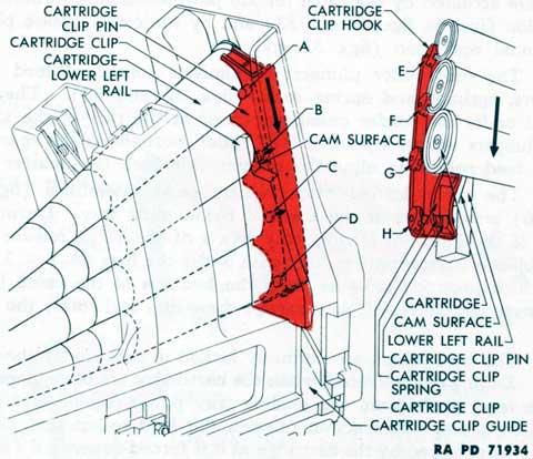
(1) The cartridges are released from the cartridge clip (red in fig. 34) as they move downward in the automatic loader. As the cartridge and clip move downward, the cartridge clip pins are forced to the rear by the cam surface of the lower rail in the rear cartridge guide. This action releases the cartridges from their hooks and from the clip. When fully released, the clip is deflected by the rear rail and is ejected through the cartridge clip guide on the left side of the gun.
(2) The action on the cartridge clip pins is shown in figure 34. Pin A has not engaged the lower rail. Pin B has engaged the lower rail and is just being forced rearward. Pins C and D have been forced fully to the rear and have released their cartridges. The action of the hooks is shown in the insert in figure 34. Hooks E and F hold
52
Figure 34-Cartridge Clip-Release From Cartridges
their cartridges. Hook G has been forced to the rear, releasing its cartridge. The cartridge has been removed from hook H.
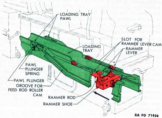
15. AUTOMATIC LOADING TRAY.
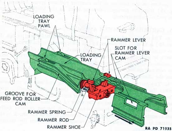
a. The functions of the loading tray are to support the cartridge until it is rammed into the chamber by the rammer, to rotate the feed roller catch heads and thus release the feed rollers, to actuate the feed rods, to operate the rammer releasing lever, and to support and actuate the cartridge rammer assembly. These duties are performed by various surfaces and mechanisms either incorporated into the shape of the tray or attached to it.
b. The loading tray (green in figs. 35 and 36) is trough-shaped to receive the cartridge. Its front end is bolted to the breech ring and recoils and counterrecoils with it. The loading tray pawls of the catch release pawl assemblies, which rotate the catch heads, are located near the front end. The cam grooves in which the feed rod rollers move are located on the sides of the tray. These grooves cause the rollers to raise the feed rods during recoil and to force them down during counterrecoil, actuating the feed mechanism and feeding another cartridge onto the loading tray.
c. The housing for the rammer rod and spring is cast in the under side of the tray toward the front. Cam slots are provided along
53
both sides in the top of the tray for the rammer levers. A beveled projection on the bottom of the rammer rod and spring housing (A, fig. 35) trips the rammer releasing lever as the loading tray nears the end of counterrecoil.
16. CARTRIDGE RAMMER ASSEMBLY.
a. The function of the cartridge rammer assembly (red in figs. 35 and 36) is to store up energy by the compression of its spring during the counterrecoil of the loading tray and, by means of the rammer levers, to grip the rim of the cartridge; then, when the rammer shoe is released, to carry the cartridge forward under the compression of the rammer spring, release it, and send it forward by its momentum into the chamber of the gun.
b. The cartridge rammer rod, head, spring, and seat are contained within the housing in the under side of the automatic loading tray. The rammer shoe is fastened to the rear end of the rammer rod. The rammer levers are pivoted in the sides of the shoe. Spring-loaded plungers force the lever heads inwardly. A leather rammer buffer pad, mounted in the front end of the housing, absorbs the shock as the rammer is driven forward by the rammer spring when the rammer shoe is released.
c. The rammer can be operated manually or automatically. The rammer must be operated manually to prepare for the firing of the initial round or before firing can be resumed if the loader has been permitted to become empty. To avoid permitting the ammunition in the loader to run out, the feed control thumb lever is usually placed in the left position when firing. This will stop automatic loading and firing when only one cartridge remains in the feed guides and one cartridge is on the loading tray.
d. Manual Operation.
CAUTION: Before initial loading, the outer safety lever should be placed in the "SAFE" position.
(1) When the hand operating lever is pulled backward as far as it will go, it causes the rammer cocking levers (par. 17 c) to force the cartridge rammer shoe rearward, compressing the cartridge rammer spring. With the hand operating lever held in the backward position to permit the catch release pistons to rotate the feed roller catch heads, a clip of cartridges is placed in the automatic loader and pushed downward until the feed rollers rotate one-quarter turn and a cartridge moves down onto the automatic loading tray. The rim of the cartridge is engaged in the grooves of the upper arm flanges of the rammer levers.
NOTE: The cartridge rammer shoe is carried farther backward during manual operation than during automatic operation.
(2) When the hand operating lever is replaced in its horizontal
54
Figure 35-Loading Tray-Rammer Shoe Held
Figure 36-Automatic Loading Tray-Rammer Shoe Released
55
position, the cocking levers will return to their normal positions and the rammer shoe will move forward a short distance. Here the rammer shoe will be engaged by the left check lever (par. 17 f), the rammer catch lever being depressed by the rammer releasing lever as the result of the projection on the under side of the loading tray depressing the toe of the rammer releasing lever.
(3) If the check levers are depressed, the rammer shoe is carried forward by the action of the compressed rammer spring. When the rammer shoe moves forward, the rammer levers carry the cartridge with it. Near the end of the forward motion of the rammer shoe, the rammer levers are forced outwardly by the cam slots in the loading tray, releasing the cartridge which is thrown into the chamber of the gun by the momentum of the ramming action.
e. Automatic Operation.
(1) During recoil, the rammer shoe assembly is carried rearward with the loading tray. As the loading tray starts forward in counter-recoil, the lower portion of the rammer shoe is engaged by the catch lever. This lever holds the rammer shoe in its rearward position while the loading tray continues to return to battery with the gun and breech ring, causing the rammer spring to become compressed.
(2) As the loading tray nears the end of counterrecoil, the beveled projection on the under side of the loading tray trips the rammer releasing lever, freeing the rammer shoe from the restraint of the catch lever.
(3) If the catch check levers are depressed, the rammer shoe is carried forward by the action of the compressed rammer spring to ram the cartridge and fire the gun.
17. AUTOMATIC LOADER CONTROL MECHANISM.
a. The automatic loader control mechanism consists of those parts of the automatic loader which cock, hold, and release the cartridge rammer shoe and which actuate the catch heads which hold and release the feed rollers. The feed roller control parts are described in paragraph 14 d.
b. The rammer control parts consist of: the rammer cocking lever shaft assembly (also known as the hand operating device) which is actuated by the hand operating lever to compress the rammer spring manually; the catch and release mechanism which holds the rammer shoe while the spring is being compressed automatically and insures that the rammer shoe will not be released until the gun has reached the end of counterrecoil; the feed control check and release mechanism which can be set to stop automatic loading and firing when only one cartridge remains in the feed guides; and the firing mechanism check and release mechanism which is controlled by the outer safety lever.
56
Figure 37-Hand Operating Lever and Hand Operating Device
57
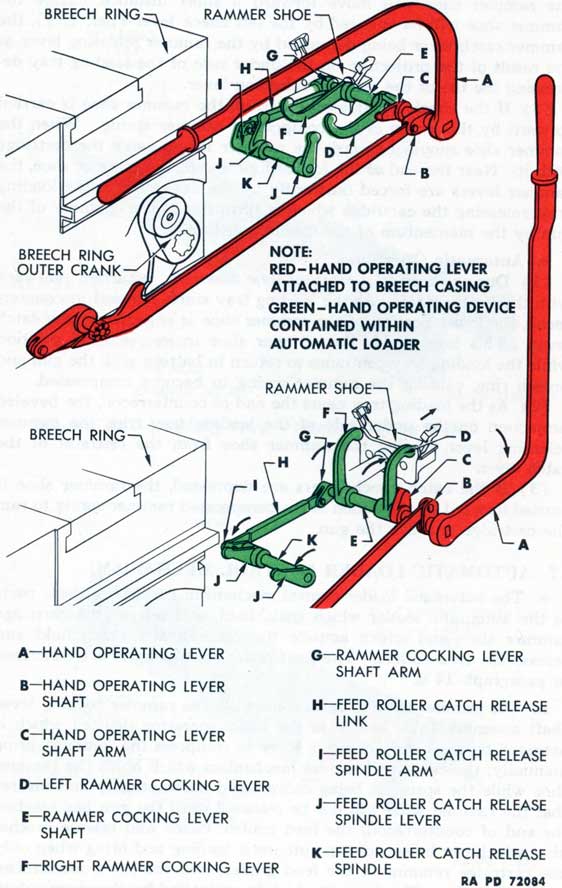
c. Rammer Cocking Lever Shaft Assembly (Hand Operating Device).
(1) This mechanism (fig. 37) is housed in the base of the automatic loader. It is operated manually by the hand operating lever to force the rammer shoe rearward and compress the rammer spring. At the same time, it presses the feed roller catch release pistons forward to contact the catch head spindle arms and rotate the feed roller catch heads. This frees the feed rollers for a one-quarter turn resulting from pressure applied on the cartridges in the magazine.
(2) The functioning of the mechanism is shown in detail in figure 37 (green). When the hand operating lever A is pulled backward, the hand operating lever shaft arm C engages the left rammer cocking lever D. The rammer cocking lever shaft E and the left and right rammer cocking levers D and F are rotated backward, carrying the cartridge rammer shoe rearward.
(3) The rammer cocking lever shaft E also rotates the rammer cocking lever shaft arm G, transmitting motion through the feed roller catch release link H and catch release spindle arm I to the catch release spindle levers J. These move the catch release pistons forward to contact the catch head spindle arms and rotate the feed roller catch heads.
d. Automatic Catch and Release Mechanism.
(1) The rammer catch lever of the automatic catch and release mechanism (uncolored in fig. 38) is the central lever of the three mounted on the rammer catch lever axis pin in the rear of the automatic loader base. Its spring-loaded plunger forces its rear end upward to engage the shoulder on the under side of the rammer shoe.
(2) If the loader is adequately charged with ammunition, the outer safety lever is set for automatic fire, and one of the firing pedals is held in the depressed position, the rammer check lever is the only one which holds the rammer shoe until the rammer spring is compressed. This lever is not released until the gun is near the end of counterrecoil.
(3) This lever is released by the beveled projection on the bottom of the loading tray engaging the front end of the rammer releasing lever when the loading tray is near the end of counterrecoil. Then, the rammer releasing lever pivots on its axis pin and its rear end lifts the front end of the rammer catch lever. The rear end of the rammer catch lever is forced downward against its spring-loaded plunger, releasing the rammer shoe. The rammer shoe is driven forward by the rammer spring unless the shoe is held by one or both check levers.
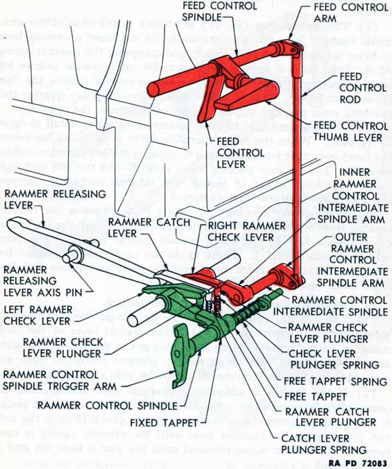
e. Feed Control Check and Release Mechanism.
(1) The function of the feed control check and release mechanism is to stop automatic loading and firing when only one cartridge remains in the feed guides and one cartridge is on the loading tray. This
58
Figure 38-Catch and Release Mechanism-All Levers Depressed
eliminates the necessity of reloading by hand as must be done if the
supply of ammunition in the loader runs out. The mechanism operates when the feed control thumb lever is pointed to the left. The
mechanism may be made inoperative to eliminate the reserve feature
by pointing the feed control lever to the right.
(2) The check lever of the feed control check and release mechanism (red in fig. 38) is the right lever of three mounted on the rammer catch lever axis pin. Its rear end is raised by a spring-loaded plunger to engage the shoulder of the rammer shoe unless the lever is held in the depressed position. The lever has an integral arm which is contacted by the inner rammer control intermediate spindle arm.
59
(3) The feed control check and release mechanism is actuated by the feed control lever at the rear and inside the automatic loader and by the feed control thumb lever at the rear and on the outside of the rear guide of the loader. Both levers act upon the inner rammer control intermediate spindle arm through the feed control spindle, arm, rod, outer rammer control intermediate spindle arm, and rammer control intermediate spindle to depress the rear end of the right check lever.
(4) The feed control check and release mechanism is controlled also by the feed control thumb lever. When this lever is in the left-hand position, the mechanism is actuated by the cartridges. It is placed in this position for single and automatic fire. When more than one cartridge is in the feed guides of the loader, the feed control lever is held to the rear of the loader by the base of the second cartridge above the feed rollers. In this case, the inner rammer control intermediate spindle arm holds the right check lever down where it has no effect on the holding of the rammer shoe.
(5) When only one round is left above the feed rollers, the feed control lever is free to lift and no longer has a restraining influence on the inner rammer control intermediate spindle arm. The rear end of the right check lever is raised by its spring-loaded plunger and holds the rammer shoe in its rearward position until the check lever is depressed. As soon as more cartridges are inserted in the loader, the releasing mechanism comes into operation again and automatic firing may be resumed.
(6) When the lever is in the right-hand position, the eccentric on the shaft of the feed control thumb lever engages and operates the short arm of the feed control lever, and through the linkage, causes the rear end of the right check lever to be depressed and the reserve feature is eliminated. This action is also utilized in releasing the rammer shoe when the weapon is unloaded.
f. Firing Mechanism Check and Release Mechanism.
(1) This mechanism (green in fig. 38) is controlled by the outer safety lever. In single fire operation, it is intended to be the last link in the holding of the rammer shoe prior to its release and the firing of the gun. It is released when the outer safety lever is set either for single fire or automatic fire and the firing pedal is depressed.
(2) The check lever of the firing mechanism check and release mechanism is the left lever of three mounted on the rammer catch lever axis pin. Its rear end is raised by a spring-loaded plunger to engage the rammer shoe unless the lever is held in the depressed position. This check lever has an integral arm which is contacted by the fixed tappet keyed to the rammer control spindle.
(3) When the outer safety lever is properly set and the firing pedal is depressed, the firing lever pawl of the breech casing firing mechanism engages and rotates the trigger and the rammer control
60
spindle trigger arm. This arm rotates the rammer control spindle and fixed tappet. The tappet depresses the firing mechanism check lever, releasing the rammer shoe, if this lever is the only one engaging the rammer shoe.
(4) When the firing lever pawl disengages the trigger, the left check lever is raised to its normal position by the action of its spring-loaded plunger. The free tappet is held against the fixed tappet by the free tappet spring, and snubs its action.
18. FIRING CYCLE, AUTOMATIC FIRE.
a. The motions of the various parts of the gun occur in a definite and interrelated manner during the firing cycle. To bring out the relationship of the parts and to illustrate their functions at specific points during the firing cycle, six drawings have been prepared (figs. 39 through 44) which show the actions and positions of the affected parts at six stages during the cycle.
b. To obtain automatic fire, certain conditions must be met. More than two cartridges must be above the feed rollers to keep the feed control check lever depressed. The feed control thumb lever must be in the left position so it will be unnecessary to reload by hand. The outer safety lever must be set on "AUTO FIRE" and one of the firing pedals must be held in the engaged position. With these conditions met, the right and left rammer check levers remain depressed and the rammer catch lever is the only one that can restrain the rammer shoe.
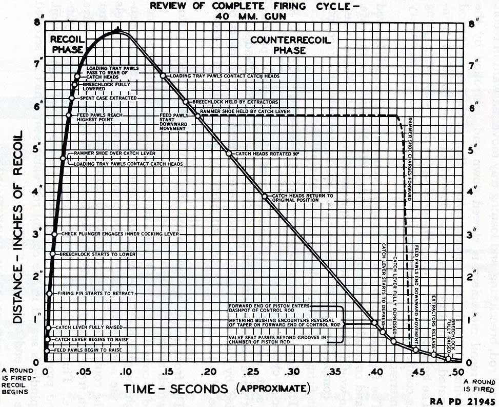
c. Part of the firing cycle occurs during recoil; the balance occurs during and at the end of counterrecoil. In the illustrations (figs. 39 through 44), the recoiling parts of the weapon are shown in red; the automatic loader is shown in green. Figure 45 shows the time required for the various parts of the gun to perform their functions during recoil and counterrecoil.
d. Recoil.
(1) FIRST STAGE. Figure 39 shows the position of the parts just after the percussion cap of the cartridge has been struck by the firing pin. Immediately after firing, the tube, breech ring, and loading tray begin to recoil and the projection on the bottom of the loading tray relieves its pressure from the rammer releasing lever, permitting the rammer catch lever to raise. During the first few inches of recoil, the outer crank rotates enough to cause the firing pin to be withdrawn into the breechblock.
(2) As recoil continues, the outer crank continues to be rotated by the cam surfaces of the side cover. The inner cranks begin to lower the breechblock. In doing so, they actuate the outer cocking lever which cocks the firing pin for the next shot. The check plunger engages the inner cocking lever.
Figure 40 - Automatic Firing Cycle - Second Stage - Breechblock Being Lowered
63
(3) As the loading tray moves backward, the cam grooves move past the rollers on the ends of the feed rods and the rollers enter the inclined portion of the grooves, raising the feed rods. The feed rods carry the feed pawls upward and over the next cartridge in the loader. The cartridges are prevented from being raised by the stop pawls. The loading tray pawls on the front of the loading tray are depressed by and pass under the lugs which extend sidewise from the feed roller catch heads.-
(4) SECOND STAGE. Figure 40 shows the position of the parts when the breechblock has been lowered part of the way in its slides in the breech ring. The feed rods, holders, and pawls are nearing their extreme upward position. The rammer shoe is over the rammer catch lever. The loading tray is free of obstructions to permit ejecting the empty case because the rammer levers were forced to the sides of the tray by their cam grooves at the same time they released the cartridge in ramming it.
(5) As the breechblock descends, the projections at the sides of the front face of the breechblock strike the toes of the extractors. The extractors are rotated toward the rear and their lips catch the rim of the cartridge case and eject it. The empty case is thrown with considerable force backward along the loading tray, through the rear cover opening, against the cartridge case deflector, and into the cartridge chute. The case is carried down the chute, under the gun, and out in front of the weapon.
(6) THIRD STAGE. Figure 41 shows the position of the parts at the end of recoil. The empty cartridge case has been ejected. The breechblock is in its lowered position. The feed rod rollers are in the upper horizontal portion of the loading tray cam grooves and the feed rods are fully raised. Recoil has been stopped by the action of the recuperator spring and the recoil cylinder. The hook-shaped heads of the extractors are over the notched tops of the projections on the front face of the breechblock. The rammer shoe is to the rear of the rammer catch lever, and the loading tray pawls are to the rear of the feed roller catch heads.
e. Counterrecoil.
(1) FOURTH STAGE. The tube, breech ring, and loading tray start to move into battery. The breechblock moves slightly upward under the action of the closing spring until it is brought to a stop and held by the extractor heads engaging the notches in the tops of the breechblock projections. The rammer shoe is engaged by the rammer catch lever, holding the shoe and compressing the rammer spring as the tube, breech ring, and loading tray move into battery (fig. 42). The right check lever is held out of engagement because there are sufficient cartridges in the loader to hold the feed control lever in its rearward position. The left check lever is held out of engagement
because one of the firing pedals is depressed and the outer safety lever is set for automatic fire.
(2) As the loading tray moves forward, the loading tray pawls on the front end of the tray engage the lugs on the feed roller catch heads, rotating the catch heads, and releasing the feed rollers for one-quarter turn. At the same time, the feed rod rollers enter the declined portion of the cam grooves on the loading tray, forcing the feed rods and pawls downward. The feed pawls engage the cartridges, forcing them downward.
(3) The lowest cartridge rotates the feed rollers, passes through them, and drops on the loading tray into the rammer shoe levers. The pawls on the feed roller catch heads engage the feed rollers, preventing them from revolving more than one-quarter turn, thus preventing more than one cartridge from passing through. The cam slots in top of the loading tray cause the heads of the rammer levers to be forced inwardly to grip the rim of the cartridge. Figure 42 shows the position of the parts as the cartridge drops onto the loading tray and its rim is engaged by the rammer levers.
(4) FIFTH STAGE. When the feed rollers have completed a quarter turn, they are relocked by the catch heads which are returned to their normal positions by their torsion springs. As the gun nears the end of counterrecoil, the beveled projection on the bottom of the loading tray trips the rammer releasing lever, freeing the rammer shoe from the restraint of the rammer catch lever.
(5) The rammer shoe is pulled forward by the rammer spring, the rammer levers carrying the cartridge forward with the shoe. As the rammer shoe nears the end of its travel, the cam slots in the tops of the loading tray force the rammer levers outward, releasing the cartridge. The cartridge is thrown forward through the U-shaped channel in the top of the breechblock and into the chamber of the gun. Figure 43 shows the position of the parts as the cartridge enters the chamber.
(6) SIXTH STAGE. After the rim of the cartridge passes through the U-shaped channel at the top of the breechblock, it engages the extractors, pulling them forward, and releasing the breechblock. The closing spring forces the breechblock upward. The beveled front surface of the breechblock engages the rear of the cartridge, forcing it completely into the chamber.
(7) As the breechblock reaches its uppermost position, the projection on the right inner crank contacts the beveled end of the check plunger, moving the plunger to the left, releasing the inner cocking lever, and permitting the firing pin to be thrust forward by the firing pin spring. The cartridge is fired, starting the cycle over again. Figure 44 shows the position of the parts at the instant before the cartridge is fired.
68
Figure 44 - Automatic Firing Cycle - Sixth Stage - Cycle Completed, Gun in Act of Firing
69
Figure 45 - Time Required for Various Parts of Gun To Perform Their Functions During Recoil and Counterrecoil
70
19. RECOIL MECHANISM.
a. The recoil mechanism consists of the recuperator spring (fig. 6) which is held in compression around the breech end of the tube, and the recoil cylinder assembly (fig. 5) which is mounted under the tubular front end of the breech casing. The recoil rod of the recoil cylinder is connected to the breech ring. When the gun is fired, the tube, recoil rod, breech ring, and loading tray move rearward in recoil.
b. The recoil movement is slowed down and controlled by the recoil cylinder and the recuperator spring. Part of the force of recoil is dissipated by the throttling of the flow of liquid in the recoil cylinder. The balance of the energy is stored up as the recuperator spring is being compressed. This energy is used to return the gun to battery in counterrecoil.
c. The forward motion of the gun in counterrecoil also is slowed down and controlled by the recoil cylinder. If this were not the case, the gun would return to battery with destructive force. There is sufficient compression of the recuperator spring to hold the recoiling parts in firing position at all angles of gun elevation.
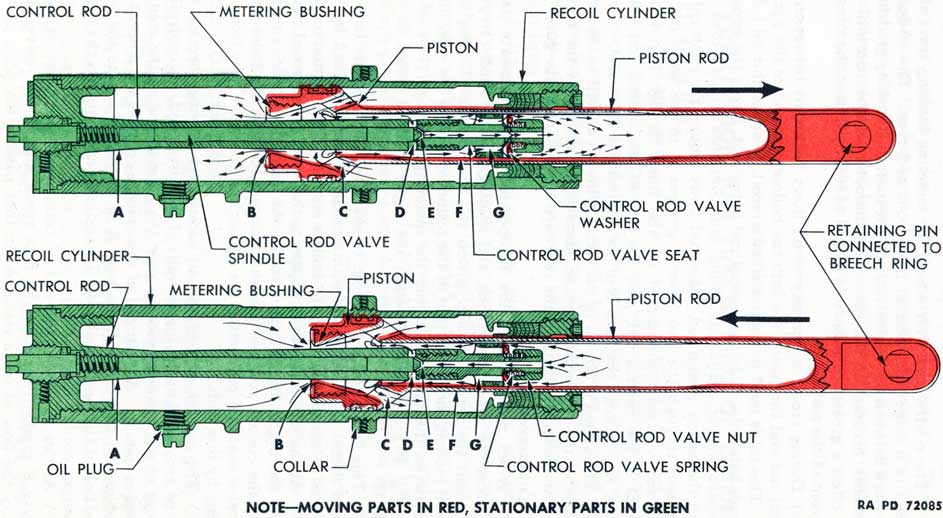
d. The recoil cylinder assembly (fig. 46) consists principally of the recoil cylinder, piston rod with piston, control rod, control rod valve seat, control rod valve spindle, and the necessary packing. Except for a slight amount of air space, all parts of the cylinder not occupied by the mechanism is filled with a mixture of 60 parts by volume of OIL, hydraulic, and 40 parts by volume of OIL, recoil, light.
e. The front end of the piston rod (fig. 46) is formed into a piston head which slides in the bore of the recoil cylinder. The rear end of the rod is connected to the breech ring. Eight inclined holes are cut through the piston. These holes are directed toward a metering bushing in the nose of the piston. The piston rod is hollow and travels over the control rod. The control rod is tapered to a larger diameter at both front A and rear B and is bored for the control rod valve spindle. This spindle protrudes from the front end of the recoil cylinder and provides a means for adjusting the speed of counterrecoil. The spindle is seated in the control rod valve seat which is screwed on the rear end of the control rod.
20. RECOIL MECHANISM FUNCTIONING.
a. Recoil.
(1) During recoil, the piston rod is drawn to the rear by the recoiling parts of the gun (upper view, fig. 46). Oil in the rear of the piston head is forced through the eight inclined holes C in the piston head, through the metering bushing B and into the space in front of the metering bushing.
71
Figure 46 - Recoil Cylinder - Action in Recoil and Counterrecoil
72
(2) The control rod, over which the metering bushing travels, is tapered to a larger diameter at both front and rear. The effective flow space between the control rod and the metering bushing gradually diminishes because of the increasing diameter of the control rod. This offers a greater resistance to the oil as it moves from the rear to the front of the piston.
(3) During recoil, a quantity of oil flows backward between the control rod and the piston rod into the hollow rear end of the piston rod. This oil is used to control counterrecoil. Part of this oil flows through four holes G in the control rod valve seat, forces the control rod valve washer against its spring, and continues on into the rear end of the hollow piston rod. More oil flows around the control rod valve seat through the two tapered grooves F in the walls of the piston rod. A small amount of oil also flows through four radial holes D in the control rod, past the end of the control rod valve spindle, and through the bore E of the control rod valve seat.
(4) The action of the oil in the recoil cylinder, as well as the compression of the recuperator spring, absorbs the energy of the recoil, and slows down and controls the rearward movement of the gun.
b. Counterrecoil.
(1) When recoil ceases, the recuperator spring reasserts itself and forces the tube, breech ring, and loading tray forward, carrying with them the recoil cylinder piston rod and piston. During this forward motion, the oil in front of the piston returns to the rear, flowing between the control rod and the metering bushing (B in lower view, fig. 46) and back through the eight inclined holes in the piston C.
(2) This flow of oil is too rapid to ease the gun back into battery without shock. Full control of counterrecoil is brought about by the restricted release of the oil in the hollow rear end of the piston rod.
(3) As this oil attempts to escape to the front of the recoil cylinder at the beginning of counterrecoil, the control rod valve spring forces the control rod valve washer forward, closing the holes G in the valve seat and preventing the oil back of the valve seat from returning by this path.
(4) The greater part of the oil escapes by flowing through the tapered grooves F in the inside walls of the piston rod. A controlled amount of oil, however, escapes past the pointed end of the control rod valve spindle. Adjustment of this spindle controls the amount of oil which can flow through the bore E in the valve seat to the four radial holes D in the control rod. This adjustment regulates the speed of counterrecoil.
(5) As the gun nears the end of counterrecoil, the two tapered grooves F gradually reduce the flow space around the valve seat. Finally the flow of oil is restricted to that passing the point of the
73
control rod valve spindle. The control rod valve spindle must be precisely adjusted for proper counterrecoil action. The reverse taper A at the front end of the control rod reduces the flow space between the control rod and the metering bushing at this point. Final buffing is accomplished by dash pot action as the piston enters its seat in the rear portion of the head of the control rod.