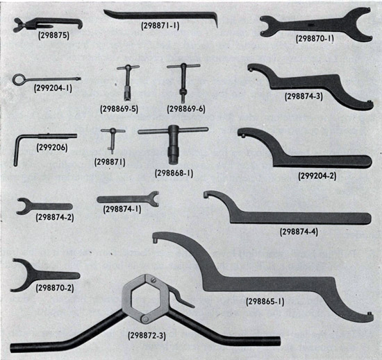
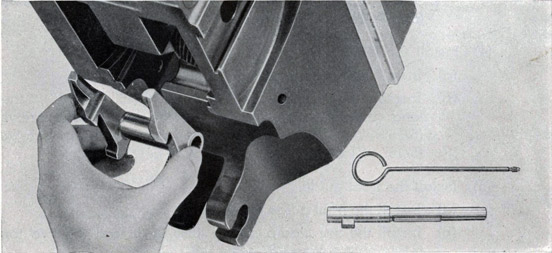
The following list gives the name, Ordnance number and use of all special tools required for assembly and disassembly. These tools are illustrated in Figure 46.
298865-1
Spanner Wrench
Used on outside casting (298862) and coaming lock nut (298866) of recoil spring compressor.
79
298868-1
Wrench
Used on closing spring cover (298685-3).
298869-5
Wrench
Used on safety plunger spring seat (298676-1).
298869-6
Wrench
Used on tray bolt (298676-2), tray bolt spring seat (298676-7), firing hole bushing (298682-2), and firing spring cover (298682-1).
298870-1
Spanner Wrench
Used on gland bushing (298739-5), throttling rod (298736-2), and collar (298737-1) of recoil cylinder.
298870-2
Spanner Wrench
Used on recoil cylinder (298730-1).
298871
Side Door Key
For side door lock.
298871-1
Hand Extractor
To extract outer crank and crankshaft.
298872-3
Flash Hider Wrench
Used on flash hider (298663) to remove barrel assembly.
298874-1
Spanner Wrench
Used on throttling bushing (298732-8).
298874-2
Spanner Wrench
Used on rammer spring seat (298793-5).
298874-3
Spanner Wrench
Used on gland nut (298662-2) and attaching nut (298662-1) of water jacket.
298874-4
Spanner Wrench
Used on gun barrel (298652).
298875
Feed Rod Spring Clamp
To compress plunger spring of feed rod holder.
299204-1
Extractor Spindle Tool
To remove extractor spindle (298674-3).
299204-2
Spanner Wrench
Used on recoil spring keeper (298662-4).
299206
Safety Plunger Key
To retract safety plunger.
80
All piece numbers given in this chapter are for the 40MM Gun Barrel, Mark 1, the 40MM Gun Mechanism, Mark 1, and the 40MM Sights, Marks 3 and 4. Piece numbers for the corresponding parts of the 40MM Gun Mechanism, Mark 2, Mark 1, Mod. 1, and Mark 2, Mod. 1, are listed in the Parts List adjacent to the Mark 1 numbers. Ordnance numbers of individual pieces are not given in the Disassembly sections, but may be found in the corresponding Assembly sections. The piece numbers of all special tools required for either assembly or disassembly are given in both sections.
A. BARREL ASSEMBLY
1. Removal of the Barrel Assembly
a. Remove the water connection at the water jacket.
(1) Turn the hand screw and lift the water connection and its gaskets from its seat on the water jacket.
(2) Depress the gun and drain the coolant through the drain on the front end of the water jacket.
b. Place the gun in the horizontal position and lock the elevation securing device.
c. Lower the breech block.
(1) Disengage the hand operating lever from the front catch bracket and pull it all the way back to lower the breech block, and then return the lever to the rear catch bracket for safety.
This prevents interference of the extractors when the barrel is turned.
d. Open the top door.
(1) Lift the knurled head at the rear of the top door and swing the lever to one side to unlatch the door. Then open the door to release the barrel lock, and latch it open.
e. Remove the barrel assembly.
(1) With two men applying the flash hider wrench (298872-3) to the flash hider and several men to handle the weight of the breech end, rotate the barrel one-half turn to the left to disengage the retaining threads. Remove the barrel assembly by pulling it forward away from the slide.
81
f. Uncock the gun mechanism.
If the gun is to remain idle for any length of time with the barrel removed, it should be uncocked.
(1) Place the hand operating lever in the front catch bracket, insert the safety plunger key (299206) in the opening in the top of the housing and turn so as to retract the safety plunger. At the same time, trip the extractor release lever on the bottom of the slide.
(2) Release the rammer by depressing the feed control lever and operating the firing mechanism.
The top door on the slide should never be closed while the barrel assembly is removed from the gun.
2. Installation of the Barrel Assembly
a. Install the barrel assembly.
(1) With two men applying the flash hider wrench (298872-3) to the flash hider and several men to handle the weight of the breech end, insert the breech end of the barrel into the forward end of the slide so that the opening for the water connection is on the bottom of the barrel.
(2) Using care to prevent damage to the threads in the housing or on the barrel, slide the barrel in as far as it will go, rotate the barrel a half turn to the right to engage the threads.
Proper assembly of the barrel with the housing will be indicated when the top door can be closed and latched without requiring force.
(3) Remove the wrench.
b. Uncock the gun by closing the breech and releasing the rammer.
c. Fill the water jacket with coolant and replace the water connections.
3. Disassembly of the Barrel Assembly
a. Remove the flash hider.
(1) Remove the three set screws.
(2) Unscrew the flash hider from the end of the barrel and remove the copper ring.
The flash hider may be removed without disturbing the recoil spring. To remove the recoil spring, the flash hider must first be removed.
82
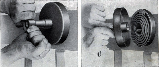
b. Remove the recoil spring.
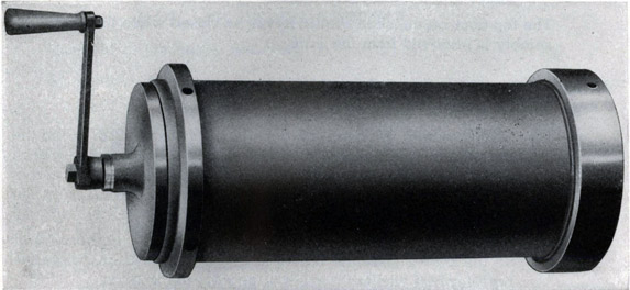
For this purpose, the recoil spring compressor (298860), Figures 47 and 48, is required.
(1) Install the outside casing of the recoil spring compressor. With the flash hider removed, install the casing (298862) threaded end first, from the front end of the barrel.
(2) Install the casing lock nut.
Use spanner wrench (298865-1) to install the casing lock nut (298866) and tighten on the threaded end of the outside casing.
Figure 47
Recoil spring compressor assembly used in removing and installing the recoil spring.
(3) Remove the spring keeper.
Spanner wrenches (298865-1 and 299204-2) are required. Remove the two set screws and unscrew the spring keeper. When the spring keeper is removed, the recoil spring assembly is confined within the outer casing of the recoil spring compressor.
(4) Remove the spring and the outer casing.
Pull the recoil spring and compressor off the front of the barrel.
(5) Install the inside casing and the screw assembly.
Install the inside casing (298861) in the nut end of the outside casing (inside the spring), and install the screw assembly (298865) in the opposite end. Using the hand crank
83
(298867), turn the screw all the way in against spring tension.
(6) Remove the casing lock nut.
Turn the screw to the right until the spring is slightly compressed and with spanner wrench (298865-1), remove the casing lock nut.
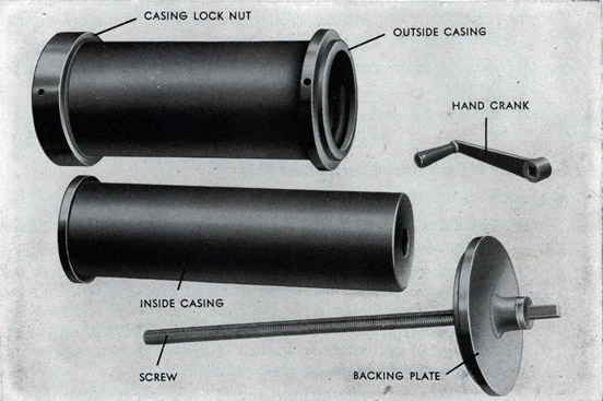
Figure 48
Recoil spring compressor disassembled.
(7) Release the spring tension.
While holding the outside casing with spanner wrench (298865-1), turn the screw to the left to release the recoil spring.
(8) Remove the spring from the compressor.
Remove the recoil spring, rear spring seat, and front spring seat from the spring compressor.
Extreme care must be exercised when removing the recoil spring as it is in high compression and if suddenly released may cause serious personal injury.
84
c. Remove the water jacket.
(1) Using spanner wrench (298874-3), unscrew the gland nut on the front of the water jacket.
(2) Remove the two packing rings and the two steel rings.
(3) Release the set screw in the attaching nut at the rear end of the water jacket. Turn off the nut, using spanner wrench (298874-3), while holding the barrel with spanner wrench (298874-4).
(4) Remove the water jacket and its gasket over the front end of the barrel.
(5) Remove the drain plug and washer.
4. Assembly of the Stripped Barrel Assembly
a. Install the water jacket.
(1) Install the gasket (298658-2) and the water jacket (298659-1) over the front end of the barrel.
(2) Put on the attaching nut (298662-1). This nut is placed over the breech end of the barrel and screwed onto the water jacket until the screw holes in the nut match the corresponding holes in the water jacket. Use spanner wrench (298874-3) on the attaching nut and spanner wrench (298874-4) on the gun barrel. Put in and tighten the set screw (298662-3).
(3) Insert the packing in the front end of the water jacket in the following order: (298658-3), (298658-5), (298658-3), (298658-4).
(4) Using spanner wrench (298874-3), screw the gland nut (298662-2) into the front end of the water jacket against the above packing rings.
(5) Install the drain plug (298739-7) and washer (298739-4).
b. Install the recoil spring.
For this operation the recoil spring compressor (298860) is required.
(1) Place the recoil spring on the inside casing.
(a) Stand the inside casing (298861) on end, and place on it the rear spring seat (298666-3), then the recoil spring (298666-1), and finally the front spring seat (298666-2).
85
(2) Place the spring under tension.
(a) Place the outside casing (298862) over the recoil spring.
(b) Insert the screw assembly (298865).
(c) While holding the outside casing with spanner wrench (298865-1), use the hand crank (298867) to turn the screw into the inside casing until the spring is compressed far enough to allow the casing lock nut to be attached.
(3) Remove the inside casing and the screw assembly.
(a) Using spanner wrench (298865-1), screw the casing lock nut (298866) on the outside casing.
(b) Crank the screw assembly to the left until the recoil spring is retained in the outside casing.
(c) Remove the screw assembly and the inside casing.
(4) Install the spring and casing on the water jacket.
Spanner wrenches (298865-1 and 299204-2) are required.
(a) Place the casing and spring, nut end first, over the water jacket.
(b) Install the spring keeper (298662-4), and screw it on tightly until the two set screw holes match the corresponding holes in the water jacket.
(c) Insert the set screws and draw them up tightly.
(5) Remove the casing lock nut and the outside casing.
(a) With spanner wrench (298865-1), remove the casing lock nut (298866), and take off the outside casing (298862).
c. Install the flash hider.
(1) Install the copper ring and the flash hider.
(a) Place the copper ring (298658-6) over the front end of the barrel. Screw the flash hider (298663-1) tightly against the copper ring, using the flash hider wrench (298872-3), until the set screw holes in the flash hider match those in the barrel.
(b) Insert the three set screws (298662-3) and draw them up tightly.
86
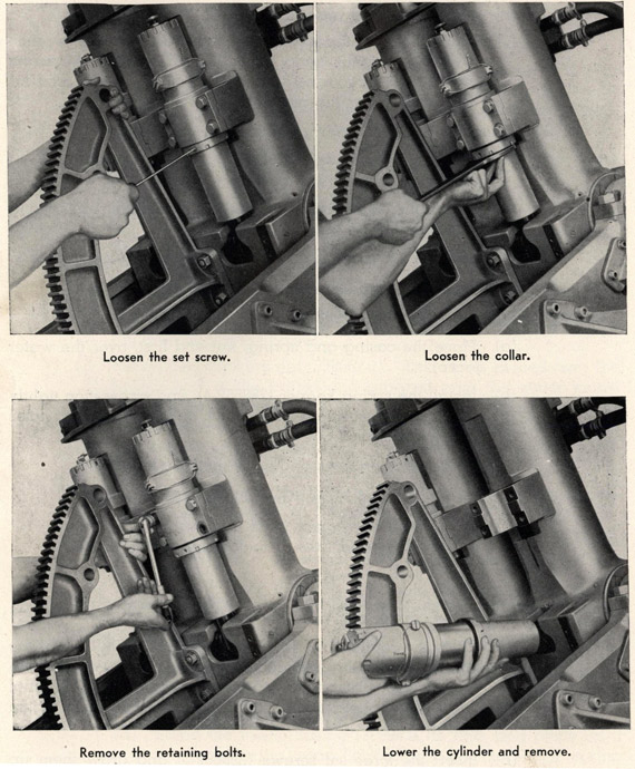
REMOVING THE RECOIL CYLINDER
Figure 49
87
B. RECOIL CYLINDER ASSEMBLY
1. Removal of the Recoil Cylinder Assembly, Figure 49
a. Loosen the recoil cylinder.
(1) Elevate the gun to about 50 degrees.
(2) Loosen the set screw and turn the collar part way off the cylinder, using spanner wrench (298870-1).
(3) Remove the four retaining bolts and take off the clamp.
b. Remove the assembly.
(1) Lower the recoil cylinder assembly until it is approximately at right angles to the slide.
(2) Disengage the securing pin from the housing lugs.
2. Installation of the Recoil Cylinder Assembly
a. Attach the assembly.
(1) Elevate the gun to about 50 degrees.
(2) Holding the recoil cylinder approximately at right angles to the slide, insert the end of the piston rod in the bottom of the slide so that the securing pin is engaged in the lugs on the bottom of the housing.
b. Bolt the recoil cylinder to the gun.
(1) Bolt the clamp (298727-1) to the pad on the bottom of the slide with the four bolts (1/2"-20 x 1-3/4").
(2) With spanner wrench (298870-1) turn the collar (298737-1) tight, and insert and tighten the set screw (1/4"-20 x 1/4").
3. Disassembly of the Recoil Cylinder Assembly
a. Remove the wire seal and the drain and fill plugs.
(1) Cut the wire seal.
(2) Remove the plugs and washers. Allow the liquid to drain.
b. Remove the locking plate.
(1) Remove the retaining bolt, then take off the washers and the locking plate.
88
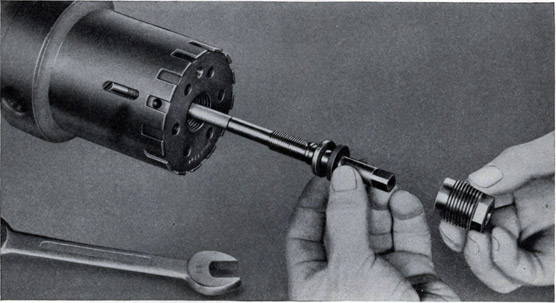
REMOVING NEEDLE VALVE
Figure 50
Removing the needle valve after the locking screw and the gland nut have been removed.
c. Remove the gland nut and the needle valve, Figure 50.
(1) Remove the locking screw.
(2) Remove the gland nut, the needle valve, and the gland rings.
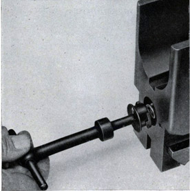
d. Remove the throttling rod.
(1) Hold the recoil cylinder either in a vise or with spanner wrench (298870-2), and unscrew the throttling rod, using spanner
wrench (298870-1).
(2) Remove the washer.
(3) Push in the piston rod and remove the throttling bushing lock
screw.
(4) Loosen the throttling bushing with spanner wrench (298874-1) and remove the throttling rod assembly.
e. Remove the securing pin.
(1) Remove the securing pin locking screw, and tap out the pin.
f. Remove the piston rod.
(1) Pull the piston rod out of the cylinder.
89
g. Remove the gland bushing, packings, and rings.
(1) Use spanner wrench (298870-1) to remove the gland bushing.
(2) Remove the rear gland ring, the four chevron packing rings, the center gland ring, the leather packing ring, and the front gland ring.
h. Remove the check valve.
(1) Tap out the taper pin.
(2) Remove the nut, then lift off the spring and the check valve.
i. Remove the valve seat and the throttling bushing.
(1) Tap out the taper pin.
(2) Unscrew the valve seat from the throttling rod, and remove the throttling bushing.
4. Assembly of the Stripped Recoil Cylinder Assembly, Figure 51.
a. Assemble the valve seat on the throttling rod.
(1) Place the throttling bushing (298732-8) over the throttling rod (298736-2), holding the end with the slots for the spanner wrench forward.
(2) Screw the valve seat (298737-2) into the end of the throttling rod, fasten with a taper pin (No. 000 x 1").
b. Assemble the nut, spring, and check valve.
(1) Install the check valve (298732-7), spring (298732-2), and nut (298732-1).
(2) Fasten the nut with the taper pin (No. 000 x 1").
c. Install the piston rod and the packing rings.
(1) Install the piston rod (298734-1) in the cylinder (298730-1).
(2) Install the front gland ring (298732-6), the leather packing ring (298735-3), the center gland ring (298735-4), the four chevron packing rings (298735-1), the rear gland ring (298735-2), and the gland bushing (298739-5). Tighten the gland bushing with spanner wrench (298870-1).
d. Install the securing pin.
(1) Tap in the securing pin (298738-1).
(2) Insert the locking screw (298739-1).
e. Install the throttling rod assembly.
(1) Push in the piston rod (298734-1).
(2) Install the leather washer (298739-6) and the throttling rod assembly.
90
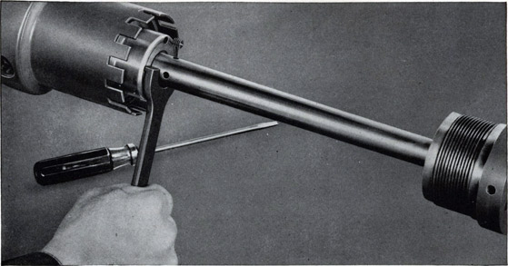
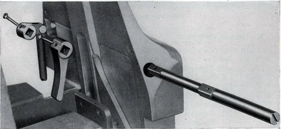
f. Tighten the throttling bushing, Figure 52, and install the locking screw.
(1) With spanner wrench (298874-1), tighten the throttling bushing
(298732-8) and install the locking screw (1/4"-20 x 5/16").
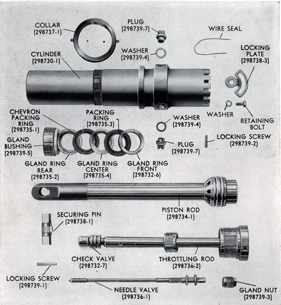
Figure 51
Recoil cylinder disassembled
91
TIGHTENING THROTTLING BUSHING
Figure 52
g. Tighten the throttling rod and install the needle valve.
(1) Holding the recoil cylinder either in a vise or with spanner wrench (298870-2), tighten the throttling rod (298736-2), using spanner wrench (298870-1).
(2) Assemble the packing ring (298732-4) and the steel gland ring (298732-5) on the needle valve (298736-1).
(3) Screw in the needle valve and tighten the gland nut (298739-3).
(4) Install the locking screw (298739-2).
h. Fill the recoil cylinder.
(1) Unscrew the needle valve two turns.
(2) Install the drain plug (298739-7) and washer (298739-4), and with the forward end of the cylinder raised to a 25 degree incline, fill the cylinder to overflowing with liquid. Install the fill plug (298739-7) and tilt the cylinder slowly several times. Again fill the cylinder to overflowing while inclined at 25 degrees.
(3) Install the fill plug and washer (298739-4) and wire the plugs
together.
92
i. Install the locking plate.
(1) Turn the needle valve all the way in, and then turn it back 1/3 turn.
(2) Install the locking plate (298738-3), the retaining bolt (5/16""24 x 5/8"), the washer (5/16"), and the lock washer (5/16").
C. LOADER ASSEMBLY
1. Removal of the Loader Assembly
a. Open the rear door.
(1) Remove the through bolt and lower the rear door, Figure 53.
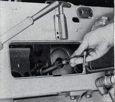
b. Remove the tray bolt.
(1) Insert the key (298871) in the lock in the side door, pressing in firmly to release the bolt spring, and turn the key to open the door.
(2) Insert wrench (298869-6) in the slot in the head of the rammer tray bolt. Push the bolt in against spring tension and rotate it 1/4 turn in either direction to remove, Figure 54.
Figure 53
Rear door-open.
Figure 54
Removing the tray bolt.
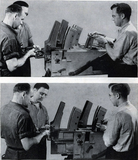
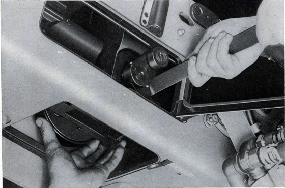
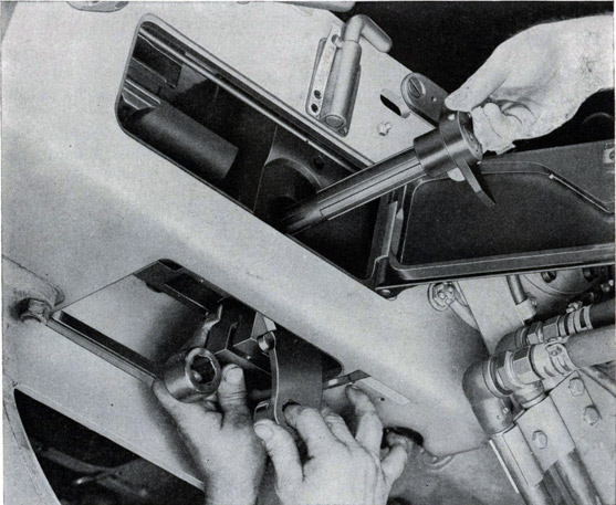
c. Remove the loader assembly.
For this operation, front lifter (346451) and rear lifter (346452) are required.
(1) Slide the assembly part way back, and with two men applying the rear lifter and one the front lifter, raise the assembly as it leaves the supporting guides in the slide, Figure 55.
To prevent damage do not allow the assembly to rest or drop on the rear door.
93
USING LOADER LIFTERS
Figure 55
The top view shows one man with lifter tool (346451) and two others with lifter tool (346452). In the bottom picture, the lifters are in place and the loader ready to be removed.
94
2. Installation of the Loader Assembly
a. Install the loader assembly.
For this operation front lifter (346451) and rear lifter (346452) are required.
(1) Install the lifters and raise the assembly carefully, starting it into the supporting guides in the slide.
(2) Remove the lifters and slide the assembly in as far as it will go.
b. Insert the rammer tray bolt.
(1) Insert the wrench (298869-6) in the slot in the head of the bolt (298676-2). Push the bolt in against spring tension and rotate 1/4 turn, matching the two arrows to lock.
(2) Close and lock the side door, using the key (298871).
c. Close the rear door.
(1) Swing the rear door (298721-1) up to the closed position.
(2) Insert the through bolt (298704-5) and turn it up tightly.
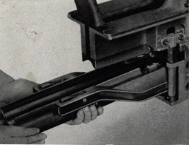
3. Removal of the Rammer Tray
a. Remove the tray assembly.
The loader assembly must be removed from the slide in order to remove the tray assembly.
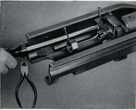
(1) Pull the tray forward out of the loader assembly, Figure 56.
(2) Remove the loose rollers from the lower ends of the feed rods.
Figure 56
Removing the rammer tray.
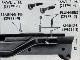
Figure 57
Tray pawls.
95
4. Installation of the Rammer Tray
a. Install the tray assembly.
(1) Install the rollers (298776-6) on the lower ends of the feed rods.
(2) Install the tray assembly, sliding it in from the front end of the loader; be careful not to push the tray in far enough that the rammer shoe passes over the catch levers.
5. Disassembly of the Rammer Tray
a. Remove the tray pawls shown in Figure 57.
(1) Tap out the taper pin and the bearing pins.
(2) Remove the pawls, their plungers, and springs.
b. Remove the rammer shoe nut and the lever bearing screws, Figure 58.
(1) Remove the cotter pin and the nut.
(2) Remove the cotter pins and the bearing screws.
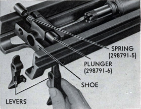
c. Remove the levers, plungers, springs, and the rammer shoe.
(1) Slide the shoe back to the large slots, press in and down to remove the levers.
(2) Remove the plungers, the spring, and the shoe, Figure 59.
d. Remove the spring seat locking screw, and the rammer.
(1) Remove the locking screw and loosen the spring seat with spanner wrench (298874-2).
(2) Remove the rammer assembly.
Figure 58
Removing bearing screw and rammer shoe nut.
Figure 59
Disassembly of the rammer shoe.
96
e. Disassemble the rammer.
(1) Tap out the taper pin, compress the spring, and unscrew the rammer head from the rod.
(2) Remove the spring and the seat.
Handle the spring carefully to avoid personal injury.
f. Remove the rammer buffer.
(1) Remove the cotter pin and the castellated nut.
(2) Using a rod (3/8" diameter x 15" long), tap out the buffer.
6. Assembly of the Stripped Rammer Tray
a. Install the rammer buffer.
(1) Insert the rammer buffer (298792), stud first, into the rammer chamber.
(2) Install and tighten the castellated nut (3/8"-24), and install the cotter pin (3/32" x 1").
b. Assemble the rammer.
(1) Place the rammer spring (298793-1) and spring seat (298793-5) on the rammer rod (298793-3).
(2) Compress the spring, and screw the rammer head (298793-2) on
the rod.
c. Install the rammer and the locking screw.
(1) Install the rammer assembly in the tray.
(2) Screw the spring seat (298793-5) into the rammer chamber with spanner wrench (298874-2) and install the locking screw (298793-4).
d. Install the rammer shoe, plungers, plunger spring, and rammer
levers.
(1) Install the rammer shoe (298794-1), the plunger spring (298791-5) and the plungers (298791-6).
(2) Slide the rammer shoe (298794-1) back to the large slot, press in and up to install the levers (right, 298795-1; left, 298795-2).
e. Install the lever bearing screws and the rammer shoe nut.
(1) Install the bearing screws (298791-9) and their cotter pins (1/8" x 1-1/4").
(2) Install the 1-1/16" rammer shoe nut (298791-7) and the cotter pin (1/8" x 1-1/2").
f. Install the tray pawls, Figure 57.
(1) Install the springs (298791-2), the plungers (298791-3), and the pawls (right, 298791-4; left, 298791-1).
(2) Insert the bearing pins (298791-8) and drive in the taper pins
(No. 00 x 1-1/8").
97
7. Disassembly of the Loader Assembly
a. Remove the guides and the feed control mechanism.
(1) Remove the front guide.
(a) Remove the two top retaining screws and then the two clamp screws.
(2) Remove the left rail of the rear guide.
(a) Remove the two retaining screws, the lower front screws,
the long through screws and the upper front screw.
(b) Remove the rails.
(3) Remove the right rail of the rear guide.
(a) Remove the two rear retaining screws and the long through screw.
(b) Remove the rail.
(4) Remove the feed control mechanism, Figure 60, and the rear guide.
(a) Remove the cotter pin and the clevis pin from the outer arm
of the intermediate control spindle, and unscrew the feed control rod from the rod end.
(b) Remove the lever and arm retaining screws and tap out the spindle.
(c) Remove the spindle arm and rod end, and the feed control lever.
Figure 60
Feed control mechanism removed from the rear guide.
98
(d) Disassemble the arm and rod end by removing the cotter pin and the clevis pin.
(e) Remove the two upper screws, the lower screws and lift off the rear guide.
(5) Remove the ammunition clip guide.
(a) Remove the retaining screws.
(b) Lift off the clip guide.
The rear guide must be removed before the clip guide can be taken off.
Figure 61
Removing a star wheel plunger.
b. Remove the frames.
To remove the frame assemblies, the guides must be removed.
(1) Remove the cross piece cover, the plunger, the spring, and the seat, Figure 61.
(a) Remove the retaining screw and the cover.
(b) Compress the springs in order to remove the seats, the springs, and the plungers.
(2) Remove the cross piece.
(a) Remove the two upper screws, the two lower screws and the cross piece.
(3) Remove the frame assemblies.
(a) Tap out the two taper pins.
(b) Remove the six retaining screws from each frame.
99
c. Remove the star wheels.
The frame assemblies must be removed in order to remove the star wheels.
(1) Tap out the taper pins.
(2) Remove the star wheel shaft retaining screws, the shafts, and the star wheels, Figure 62.
Figure 62
Removing a star wheel after the retaining screw has been removed. The star wheel shaft and extension piece are being withdrawn from the star wheel.
d. Remove and disassemble the feed rods.
The tray assembly must be removed in order to remove the feed rod assemblies. Instructions for removal are given on page 94. It is not necessary, however, to remove the frame assemblies in order to service the feed rod assemblies. The following instructions apply to either of the feed rods.
(1) Remove the feed rod assembly.
(a) Use an offset screw driver to remove the retaining screw.
(b) Rotate the star wheel and raise the assembly out of the frame.
100
(2) Remove the feed pawl holder.
For this operation the clamp (298875) is required.
(a) Install the clamp and tighten until the spring is completely
compressed.
(b) Slide the holder and lift it out, Figure 63.
(c) Loosen the clamp.
(d) Remove the plunger and spring.
(3) Remove the pawls.
(a) Push out the bearing pins.
(b) Remove the bushings, springs, and pawls.
Figure 63
Removing the feed pawl holder.
e. Remove and disassemble stop pawls.
The loader assembly need not be removed in order to remove the stop pawl assembly.
(1) Remove the stop pawl assembly.
(a) Tap out the dowel pin.
(b) Remove the screws and washers and lift out the assembly.
(2) Remove the pawls.
(a) Push out the bearing pins.
(b) Remove the bushings, springs, and pawls.
f. Remove and disassemble the star wheel catch mechanisms.
It is not necessary to remove this assembly when the frame assemblies are to be removed.
101
(1) Remove the catch head bracket.
(a) Remove the cotter pins and the castellated nuts.
(b) Tap out the retaining screws and remove the bracket.
(2) Remove the catch head.
(a) File off the riveted ends of the taper pin.
(b) Rotate the catch arm and insert a block between it and the casting to place the catch head taper pin in position to be driven out. Drive out the taper pin, Figure 64.
(c) Remove the catch head.
Figure 64
Removing the catch head.
Figure 65
Catch head.
(3) Remove the catch arm, spring and spindle.
(a) Tap the taper pin out of the catch arm.
(b) Raise the spindles and remove the catch arm and the spring.
(c) Remove the spindle through the bottom.
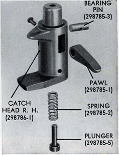
(4) Disassemble the catch head, Figure 65.
(a) Remove the retaining screw and the bearing pin.
(b) Push out the pawl, the plunger and the spring.
102
g. Remove and disassemble the star wheel catch release and the rammer cocking levers.
(1) Remove the catch release spindle retaining pins.
(a) Tap out the three taper pins.
(2) Remove the catch release spindle and the catch release levers.
(a) Tap out the spindle and pull out the catch release levers.
(3) Remove the catch release pistons.
(a) Rotate the catch heads and extract the pistons.
Figure 66
Removing the outboard rammer cocking lever.
(4) Remove the catch release link and the rammer cocking lever
shaft arm.
(a) Remove the lock screw and the shaft arm.
(b) Remove the pin from the shaft arm.
(c) Take out the cotter pin and remove the clevis pin from the
link.
(5) Remove the outboard rammer cocking lever, Figure 66.
(a) Tap out the taper pin.
(6) Remove the inboard rammer cocking lever and shaft.
(a) Tap out the taper pin.
(b) Remove the shaft and lever.
103
h. Remove and disassemble the catch lever mechanisms.
(1) Remove the rammer control spindle.
(a) Tap out the taper pin from the fixed tappet.
(b) Remove the spindle.
(c) Remove the fixed tappet, the free tappet, the spring, and the collar.
(d) Tap out the taper pin to remove the arm from the spindle.
(2) Remove the catch levers and their plungers.
(a) Depress the plungers and install cotter pins or wire in the holes in the lower ends to hold them down.
Figure 67
Removing the catch levers and the bearing pin.
(b) Tap out the taper pin from the bearing pin.
(c) Tap out the bearing pin and remove the loader catch lever (inboard), tray catch lever (center), and the trigger catch lever (outboard), Figure 67.
(d) Depress the plungers and remove the holding pins or wire.
(e) Remove the plungers and the springs.
(3) Remove the intermediate control spindle and arms.
(a) Tap out the taper pin from the outer arm, and remove the inner arm and spindle.
(b) Tap out the taper pin to remove the inner arm.
(4) Remove the rocker arm.
(a) Tap out the taper pin from the bottom of the base.
(b) Tap out the bearing pin and remove the lever.
104
8. Assembly of the Stripped Loader Assembly
a. Assemble and install the catch lever mechanisms.
(1) Install the rocker arm.
(a) Insert the rocker arm (298746-1) and the bearing pin (298748-7).
(b) Tap in the taper pin (No. 000 x 1") from the top of the base.
(2) Install the intermediate control spindle and arms.
(a) Install the inner arm (298750-4) on the spindle (298750-3) and fasten with a taper pin (No. 000 x 3/4").
(b) Insert the spindle into the base from the inside and attach the outer arm (298752-4) with a taper pin (No. 000 x 7/8").
(3) Install the catch levers and their plungers.
(a) Insert the two end plungers (298748-4), the center plunger (298748-2), and the springs (298748-5) in the holes in the bottom of the base.
(b) Depress the plungers and insert wires or cotter pins in the holes in the lower ends to hold them down.
(c) Start the bearing pin (298748-1) into the base and thread it through the holes in the following levers: The trigger catch lever (298747-4) (outboard), the tray catch lever (298747-1) (center), and the loader catch lever (298749-4) (inboard). Push the bearing pin the rest of the way into the base.
(d) Install the taper pin (No. 1 x 1-1/4").
(e) Depress the plungers and remove the holding pins or wire.
(4) Install the rammer control spindle.
(a) Install the arm (298750-2) on the spindle (298750-1) and fasten with a taper pin (No. 000 x 7/8").
(b) Start the spindle (298750-1) into the base and thread it through the following: the fixed tappet (298749-2, the free tappet (298749-3), the spring (298749-1), and the collar (298748-8). Push the spindle the rest of the way into the base.
(5) Adjust the tray catch lever.
(a) Turn the adjusting screw (298748-6) in the bottom of the base to bring the tray catch lever level with the two side
105
levers. After the loader is assembled in the slide, cock the gun and check the clearance between the rammer shoe and the tray catch lever using a (".020-".050) thickness gauge and a 3" straight edge. It should be between ".020-".050. If it is found that the clearance exceeds ".050, remove the rocker arm and grind off the top surface of the front end. Grind as much material off the rocker arm as is required to bring the clearance to ".050.
If the clearance is found to be less than ".020, replace the lever.
b. Assemble and install the star wheel catch release and the rammer cocking levers.
(1) Install the inboard cocking lever and shaft.
(a) Install the shaft (298751-1) and the lever (298751-3) in the base.
(b) Install the taper pin(1 x 1-1/4").
(2) Install the outboard rammer cocking lever.
(a) Install the lever (298769-4) and fasten with a taper pin (No. 1 x 1-1/4").
(3) Install the catch release link, the spindle arm, and the rammer cocking lever shaft arm.
(a) Assemble the link (298746-3) and the spindle arm (298752-3) with the clevis pin (298746-5) and the cotter pin (1/16" x 1/2").
(b) Install the pin (298748-9) through the link and shaft arm (298751-2).
(c) Install the shaft arm on the rammer cocking lever shaft, and insert the lock screw (No. 8-32 x 3/8", dog point headless).
(4) Install the catch release pistons.
(a) Rotate the catch heads and install the pistons (298752-1).
(5) Install the catch release levers.
(a) Locate the catch release levers (298752-2) in the base and insert the spindle (298746-4). Install the spindle arm on the end of the spindle.
(6) Install the catch release spindle retaining pins. (a) Install the three taper pins (No. 1 x 7/8").
106
c. Assemble and install the star wheel catch mechanism.
(1) Assemble the catch head, Figure 65, page 101.
(a) Install the spring (298785-2), the plunger (298785-5), and the pawl (298785-1) in the catch head.
(b) Install the bearing pin (298785-3) and the retaining screw (No. 5-40 x 1/2").
Figure 68
Stop pawls.
(2) Install the catch arm, spring, and spindle.
(a) Insert the spindle (298753-2) through the bottom of the base.
(b) Raise the spindle and install the arm (right, 298747-2; left, 298747-3) and the spring (right, 298753-1; left, 298746-2).
(c) Tap the taper pin (No. 0 x 3/4") into the arm.
(3) Install the catch head.
(a) Install the catch head (right, 298786-1; left, 298787-1).
(b) Tap the taper pin (No. 0 x 1") into the catch head.
(c) Rivet the end of the toner Pin.
107
(4) Install the catch head bracket.
(a) Install the bracket (298785-4) and insert the retaining screws (298785-6).
(b) Install the castellated nuts (5/16"-24) and insert the cotter pins (1/16" x 5/8").
d. Assemble and install the stop pawls.
(1) Install the pawls in the holder, Figure 68.
(a) Install the springs (298754-2) and bushings (298754-3) in the pawls (298754-5).
(b) Place the pawls in the holder (left, 298756-1; right, 298754-1) and insert the bearing pins (298754-4).
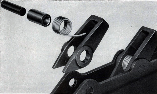
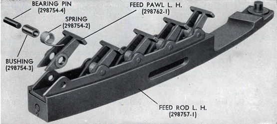
Figure 69
Feed pawls.
(2) Install the stop pawl assembly.
(a) Insert the assembly in the frame.
(b) Insert the screws (5/16"-24 x 1-1/8") and washers (5/16")
(c) Tap in the dowel pin (5/16" x 1-3/8").
e. Assemble and install the feed rods.
(1) Install the pawls in the holder, Figure 69.
(a) Assemble the springs (298754-2), bushings (298754-3) and pawls (right, 298758-1; left, 298762-1).
(b) Insert the pawls in the holders (left, 298757-2; right, 298761-1) and push in the bearing pins (298754-4).
108
(2) Install the feed pawl holder in the feed rod.
For this operation, clamp (298875) is required.
(a) Install the plunger spring (298759-1) and the plunger (298759-3) in the feed rod.
(b) Install the clamp and tighten until the spring is completely compressed.
(c) Insert the holder in the feed rod and slide it down.
(d) Loosen the clamp.
(3) Install the feed rod assembly in the frame.
(a) Insert the feed rod assembly in the slot in the frame, rotating the star wheel as the feed rod is pushed down to the bottom of the groove.
(b) Using an offset screwdriver, install the retaining screw (298759-2).
f. Install the star wheels.
(1) Assemble the star wheel on the shaft (left, 298774-1; right, 298771-1) and install it in the loader with the retaining screw (298776-1).
(2) Tap in the taper pin (No. 000 x 7/8").
g. Install the frames.
(1) Install the frame (right, 298764-1; left, 298763-1) and insert the six retaining screws (3/8"-24 x 5/8").
(2) Tap in the two taper pins (No. 7 x 2").
h. Install the star wheel plungers.
(1) Install the cross piece.
(a) Install the cross piece (298769-1), the two lower screws (3/8"-24 x 7/8").
(2) Install the star wheel plungers, springs, and seats, and the cross piece cover.
(a) Install the plungers (298777-1), the springs (298777-2), and the seats (298777-3).
(b) Install the cross piece cover (298769-3) and the retaining screw (1/4"-28 x 1/2").
i. Install the guides and the feed control mechanism.
(1) Install the ammunition clip guide.
109
(a) Install the guide (298769-2) and the retaining screws (5/l6"-24 x 1/2").
(2) Install the rear guide and feed control mechanism.
(a) Install the rear guide (298767-1), and insert the four retaining screws (3/8"-24 x 7/8").
(b) Assemble the rod end (298777-4) and the spindle arm (298753-3) with the clevis pin (298748-3).
(c) Install the cotter pin (1/16" x 5/8").
(d) Insert the spindle (298784-3), and install the lever and arm retaining screws (298776-9).
(e) Screw the rod (298776-8) into the rod end (298777-4).
(3) Install the right rail.
(a) Install the rail (298778-1) and insert the long through screw (298776-2) and the two rear retaining screws (5/16"-24 x 3/4").
(4) Install the left rail.
(a) Install the two rails (298782-1 and 298780-1).
(b) Install the upper front screw (5/16"-24 x 1"), the long through screw (298776-2), the lower front screws (5/16"-24 x 1/2"), and the two rear retaining screws (5/16"-24 x 3/4").
(5) Install the front guide.
(a) Install the front guide (298766-1).
(b) Install the two clamp screws (298776-3) and the two top retaining screws (3/8"-24 x 5/8").
(6) Adjust the feed control mechanism.
(a) Install a ".25 gauge block or thickness gauge under the front end of the loader catch lever (inboard).
(b) Insert two dummy rounds in the loader to position the feed control lever in the rear guide. Hold up in position the outer arm on the intermediate control spindle, and adjust the length of the feed control rod until all the up and down motion is eliminated. When the clevis pin (298748-3) is inserted, install the cotter pin (1/16" x 5/8").
110
D. HOUSING ASSEMBLY
The barrel, recoil cylinder and loader assemblies must be removed before the housing can be removed or installed, and the slide should be in a horizontal position.
1. Removal and Disassembly of the Housing Assembly
It is unnecessary to remove the housing assembly for removal or installation of the extractors, the breech block assembly, the closing spring assembly, the outer crank assembly, and the inner cranks.
a. Remove the barrel assembly.
Instructions for removing the barrel assembly are given on page 80.
Figure 70
Removing the extractors.
b. Remove the loader.
Instructions for removing the loader assembly are given on page 92.
c. Remove the recoil cylinder.
Instructions for removing the recoil cylinder assembly are given on page 87.
111
d. Remove the bottom cover.
(1) Pull down on the knurled head and swing the lever to one side to release the arm.
(2) Allow the cover to drop out of place.
e. Remove the breech block.
Instructions for removing the breech block assembly are given on page 115.
f. Remove the housing.
(1) Close the top door and pull the housing out of the back end of the slide.
g. Remove the extractors.
For this operation the extractor spindle tool (299204-1) is required.
(1) Screw the tool into the threaded end of the extractor spindle, swing both extractors to the extreme rear position, and then swing the extractor spindle arm to the extreme forward position.
(2) Pull out the spindle and dismount the extractors through the bottom of the housing, Figure 70.
(3) Swing the extractor spindle arm to the extreme rear position and remove it from the breech housing.
h. Remove the barrel lock.
(1) Swing the barrel lock up, pull the safety catch arm out of the housing, and remove the barrel lock.
i. Remove the safety plunger.
(1) Use wrench (298869-5) to unscrew the spring seat.
(2) Remove the spring and the safety plunger.
j. Remove the crankshaft bushing.
(1) Remove the locking screw.
(2) Slide the crankshaft bushing out of the housing.
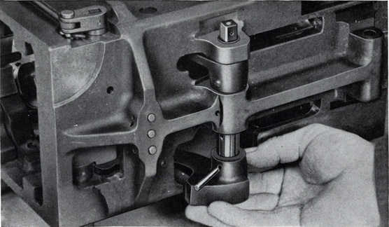
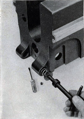
k. Remove the tray bolt spring seat.
(1) Remove the locking screw and unscrew the spring seat, using wrench (298869-6), Figure 71.
(2) Remove the spring and the sleeve.
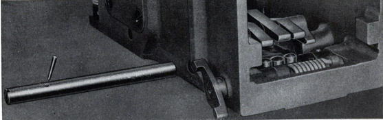
l. Remove the barrel stop.
(1) Remove the barrel stop retaining screw and pull the barrel stop out of the housing, Figure 72.
112
m. Remove the outer crank from the crankshaft.
(1) Remove the elastic stop nut, tap out the lock pin and remove the crank from the shaft.
(2) Remove the screw, washer, and the roller.
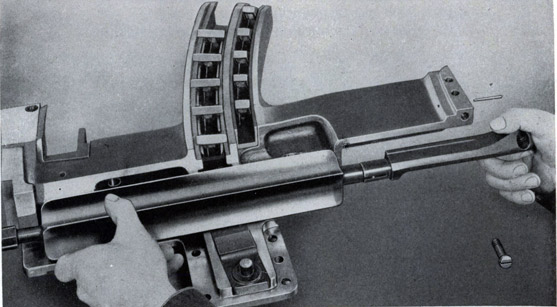
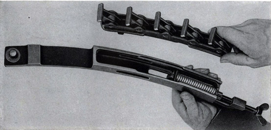
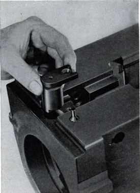
n. Remove the breech block closing spring.
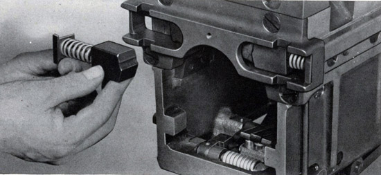
(1) Mount the closing spring assembly on the bracket at the rear of the carriage platform and use wrench (298868-1) to remove the cover, Figure 73. To do this, push the cover in against spring tension and turn it to the left to release.
(2) Remove the spring.
(3) Remove the spring case from the bracket.
Figure 71
Removing the tray bolt spring seat.
Figure 72
Removing the barrel stop.
113
DISASSEMBLY OF THE CLOSING SPRING
Figure 73
When being assembled or disassembled the closing spring assembly is mounted in a bracket on the rear of the carriage platform.
2. Assembly and Installation of the Housing Assembly
a. Assemble the crankshaft.
(1) Install the roller (298672-3), washer (298672-4), and screw (298672-7) on the crank.
(2) Mount the crank (298687-1) on the shaft (298687-2) and install the lock pin (298681-3) and the elastic stop nut (299210-1).
b. Assemble the breech block closing spring.
(1) Install the spring case (298685-4) in the bracket on the rear of the carriage platform and install the spring (298685-1), convex side out, in the case.
(2) To install the cover (298685-3) it is necessary to press the cover in against spring tension as it is being turned to the right by the wrench (298868-1) to lock it to the case.
c. Install the barrel stop.
(1) Insert the barrel stop (298673-2) in the housing and install the retaining screw (298672-7). Tighten the screw firmly.
d. Install the tray bolt seat and spring.
(1) Insert the sleeve (298676-4), the spring (298676-6), and the seat (298676-7) in the inboard lug on the housing and screw the seat in tightly, using wrench (298869-6).
(2) Install the locking screw (1/4"-20 x 1/4").
114
e. Install the crankshaft bushing.
(1) Slide the bushing (298672-8) into position in the housing and insert the locking screw (298672-2).
f. Install the safety plunger.
(1) Install the safety plunger spring (298676-3) and the safety plunger (298676-5) in the housing.
(2) Insert the spring seat (298676-1) and screw it in tightly, using wrench (298869-5).
g. Install the barrel lock.
(1) Place the barrel lock (298673-1) in an upright position in the housing and install the safety catch arm (298671-2).
h. Install the extractors.
For this operation, extractor spindle tool (299204-1) is required.
(1) Assemble the extractors (298674-1 and 298674-2) together and place them in position in the housing with the hooked sides down.
(2) Install the extractor spindle arm (298675-1) by swinging it rearward and pushing it all the way into position.
(3) With the extractor assembly in the rear position and the extractor spindle arm swung forward, install the spindle (298674-3).
i. Install the housing.
(1) Install the housing in the rear end of the slide, and push the housing all of the way forward. Open the top door to retain the housing in position.
j. Install the breech block.
Instructions for installing the breech block are given on page 118.
k. Install the bottom cover.
(1) Install the cover (298705-1) in position, and lock it by lifting the knurled head (298701-3) and swinging the lever (298713-4) to
one side until it latches in the rear notch in the cover.
l. Install the recoil cylinder.
Instructions for installing the recoil cylinder are given on page 87.
m. Install the loader.
Instructions for installing the loader are given on page 94.
n. Install the barrel assembly.
Instructions for installing this assembly are given on page 81.
115
E. BREECH BLOCK ASSEMBLY
1. Removal and Disassembly of the Breech Block Assembly
The breech block assembly may be removed and installed with the barrel removed or in position in the housing and slide.
The breech block may also be removed and installed with the gun mechanism in a horizontal or depressed position.
If the gun mechanism is mounted on the carriage, it is preferable to depress the gun to a convenient working angle.
To remove the breech block assembly the gun must be unloaded and the breech block uncocked.
Figure 74
Opening the side door.
a. Open the top door.
(1) To open the top door, lift the knurled head to release the lever and swing it to one side to unlatch the door.
(2) Swing the top door fully open to engage its locking catch.
b. Open the side door.
(1) Insert the key (298871) and turn it to release the catch.
(2) Swing the door open, Figure 74.
116
USING THE HAND EXTRACTOR TOOL
Figure 75
c. Remove the bottom cover.
(1) Pull down on the knurled head and swing the lever to one side to release the arm and the cover.
d. Remove the breech block closing spring assembly.
(1) Pull the crankshaft out about 2" and remove the closing spring assembly.
If the crankshaft is stuck and cannot be easily pulled out, pry it out with the hand extractor (298871-1), Figure 75.
e. Remove the inner cranks.
(1) Support the breech block assembly and withdraw the crankshaft.
(2) Lower the breech block until it engages the safety plunger, and remove the inner cranks.
117
REMOVING THE BREECH BLOCK
Figure 76
While one man withdraws the crankshaft, another is shown removing the inner cranks and the breech block.
If the barrel is in position, the safety plunger will not function and the breech block assembly will come out with the inner cranks, Figure 76.
f. Remove the breech block.
(1) Insert the safety plunger key (299206) in the hole in the top of the housing and turn it to release the breech block assembly.
(2) While turning the key, catch the breech block as it slides out of the bottom of the housing.
118
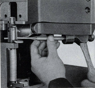
g. Remove the firing pin.
(1) Insert the wrench (298869-6) in the slot in the firing spring cover, Figure 77, push the cover in against spring tension, and give it a quarter turn in either direction to remove.
(2) Remove the firing spring and the firing pin.
h. Remove the firing hole bushing.
(1) Tap against the smooth end, but do not try to force the pin all the way out of the breech block.
(2) Insert the wrench (298869-6) from the rear of the breech block and unscrew (clockwise) the firing hole bushing. Remove the locking pin.
Figure 77
Removing the firing spring cover.
Figure 78
Removing the outer cocking lever.
i. Remove the cocking levers and the sear.
(1) Push the sear in against spring tension, and remove the outer
cocking lever, Figure 78.
(2) Remove the inner cocking lever, the sear, and the sear spring.
2. Assembly and Installation of the Breech Block Assembly
a. Install the sear and cocking levers.
(1) Install the sear spring ( 298681-2), the sear (298680-1) and the
inner cocking lever (298682-4).
119
(2) Push the sear in against spring tension and insert the outer cocking lever (298680-2).
b. Install the firing hole bushing.
(1) Insert the locking pin (298681-4) with the curved slot to conform with the shape of the hole for the bushing.
(2) Screw in the bushing (298682-2), tighten it with the wrench (298869-6) and use a 1/8" drift in driving the locking pin tight, driving against the slotted end.
c. Install the firing pin.
(1) Insert the firing pin (298682-3) and the firing spring (298681-1).
(2) Insert the wrench (298869-6) in the slot in the firing spring cover, push the cover (298682-1) in against spring tension, and give it a quarter turn to match the arrows.
d. Install the breech block.
(1) Insert the safety plunger key (299206) in the hole in the top of the housing and turn it to retract the safety plunger.
(2) Slide the breech block up from the bottom. Turn the key to release the safety plunger, and allow the breech block to slide down until it is locked by the safety plunger.
If the barrel is in position, the safety plunger is not operative and the block, the inner cranks, and the crankshaft must be installed at the same time.
e. Install the inner cranks.
(1) Insert the inner cranks (left, 298683-1; right, 298683-2), and after retracting the safety plunger with the key, slide the breech block and cranks up in the housing as far as they will go, tripping the extractor release lever so that the block will clear the extractor.
(2) Insert the crankshaft (298686), with the flat surface on the lower arm of the outer crank parallel with the bottom of the side door, pushing it in far enough to support the breech block and inner cranks but not far enough to prevent the assembly of the closing spring.
f. Install the closing spring assembly.
(1) Slide the closing spring assembly up in the T slot in the side of the housing and push the crankshaft all the way in.
g. Install the bottom cover, close and lock the side door and top doors.
120
F. SLIDE ASSEMBLY
1. Removal and Disassembly of the Top Door
The top door assembly may be removed at any time without disturbing any of the other units. The door catch and locking catch assemblies may be removed without dismounting the door.
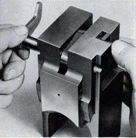
Make sure the gun is unloaded and uncocked before removing the top door. If the barrel is dismounted, install the breech block locking bolt (298716-1).
a. Remove the top door.
(1) Open the top door by lifting the knurled head and swinging the lever to one side.
(2) Remove the two retaining screws and tap the door assembly gently to dislodge the dowel pin.
(3) Carry the door forward to disengage it from the barrel lock.
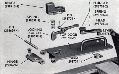
Figure 79
Top door assembly.
b. Remove the locking catch assembly.
(1) Remove the four retaining screws and dismount the catch assembly.
(2) To disassemble the locking catch assembly, remove the retaining pin, the pivot pin, the locking catch, and the spring from the bracket.
121
c. Remove the door catch.
(1) Remove the taper pin, the arm, and the lever.
(2) The knurled head, the plunger, and spring, may be removed by grinding off the riveted end of the plunger.
d. Remove the door hinge.
(1) Remove the retaining pin, the hinge pin and the hinge from the top door.
2. Assembly and Installation of the Top Door, Figure 79
The door catch and the locking catch assemblies may be installed before or after the door is installed on the slide.
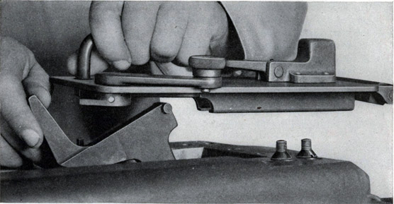
Figure 80
Installing the top door.
a. Install the hinge on the door.
(1) Install the hinge (298699-1), the hinge pin (298699-4), and the taper pin (No. 000 x 5/8").
b. Install the door catch assembly.
(1) Install the lever (298713-4), the arm (298701-1), and the taper pin (No. 0 x 1").
c. Install the locking catch assembly.
(1) To install the locking catch assembly, install the spring (298699-3), the catch (298699-2), the pivot pin (298703-4), and the taper pin (No. 000 x 5/8").
122
(2) Mount the catch assembly in position on the door and install the four retaining screws (10-32 x 1/2").
d. Install the top door.
(1) Insert the barrel lock in the top door guide, Figure 80, and then slide the door rearward into position.
(2) Install the hinge retaining screws (5/16"-24 x 1/2") and the dowel pin (No. 2 x 3/4").
(3) After the door is closed, lift the knurled head (298701-3) and swing the lever (298713-4) forward to engage the arm ( 298701-1) .
3. Removal and Disassembly of the Side Door
The side door assembly may be removed at any time without disturbing any of the other units. The catch may be removed without dismounting the side door.
Make sure the gun is unloaded and uncooked.
a. Remove the side door.
(1) Open the side door with the key.
(2) Remove the door hinge bolt and take off the door assembly.
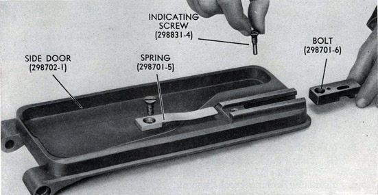
b. Remove the catch, Figure 81.
(1) Remove the spring retaining screw and slide the spring out toward the door hinge.
Figure 81
Removing the side door catch.
123
(2) Remove the indicating screw and slide the catch out of position.
4. Assembly and Installation of the Side Door
a. Install the catch.
(1) Slide the catch bolt (298701-6) into 'position and install the indicating screw (298831-4).
(2) Slide the spring (298701-5) into position and install the spring retaining screw (1/4--28 x 5/8").
b. Hang the side door.
(1) Install the door hinge bolt (298703-1) after the door (298702) has been placed in position.
(2) Close and lock the side door with the key (298871).
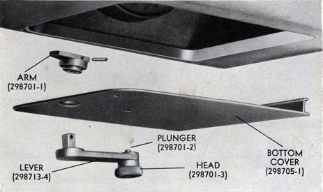
5. Removal and Disassembly of the Bottom Cover
The bottom cover assembly may be removed at any time without disturbing any of the other units.
a. Remove the bottom cover.
(1) Pull down the knurled head and swing the lever to one side to release the cover assembly.
b. Remove the cover catch.
(1) Remove the taper pin, the arm and the lever.
(2) The knurled head, the plunger, and the spring may be removed by grinding off the riveted end of the plunger.
Figure 82
Bottom cover.
124
6. Assembly and Installation of the Bottom Cover, Figure 82
a. Install the cover catch.
(1) Assemble the spring (298701-4), the plunger (298701-2), and the knurled head (298701-3).
(2) Insert the lever (298713-4) in the cover (298705-1) and attach the arm (298701-1) with a taper pin (No. 0 x 1").
b. Install the cover.
(1) Insert the flanged edge of the cover into the rear part of the cover opening, and swing the cover up into place.
(2) Swing the cover catch to lock the cover in place.
7. Removal and Disassembly of the Rear Door
The rear door assembly may be removed at any time without disturbing any of the other units. The case deflector, the deflector brackets and the recoil indicator assembly may be removed without dismounting the rear door.
Make sure the gun is unloaded before removing the rear door.
a. Remove the rear door.
(1) Remove the through bolt.
(2) Remove the taper pin, hinge pin, and the door assembly.
The door must be partly closed in order to remove the taper pin.
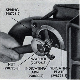
b. Remove the recoil indicator, Figure 83.
(1) Remove the taper pin, nut, spring, washer and the indicating arm.
(2) Remove the retaining screws, the washer and the indicating plate, and the stud.
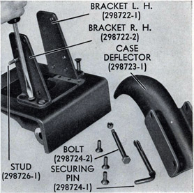
c. Remove the case deflector and brackets, Figure 84.
(1) Remove the cotter pin, castellated nut, hinge bolt, securing pin and the deflector.
(2) Remove the bracket retaining screws and the brackets.
8. Assembly and Installation of the Rear Door
a. Install the case deflector brackets.
(1) Install the brackets (298722-1 and 298722-2) and insert the retaining screws (3/8"-24 x 7/8").
(2) Install the deflector (298723-1) and insert the hinge bolt (298724-2), the castellated nut (3/8"-24) and the retaining cotter pin (3/32" x 1").
(3) Install the securing pin (298724-1).
125
b. Install the recoil indicator.
(1) Install the stud (298726-1) , the indicating plate (298725-2), the retaining screws (5/16"-24 x 3/8"), and the washers (5/16").
(2) Install the indicating arm (298809-2), the washer (298726-3), the spring (298726-2), the retaining nut (298725-3), and the taper pin (No. 00 x 1").
Figure 83
Removing recoil indicator.
Figure 84
Removing case deflector brackets.
(3) Position the indicating plate so that the indicating arm will give a true indication of the amount of recoil. To do this, set the arm so that the front surface of the stud at its lower end is at a given distance back of the rear end of the tray. Seven or eight inches or any dimension that is engraved on the plate can be used.. With the indicating arm definitely located, loosen the screws holding the indicating plate, and adjust the plate so that the upper end of the indicating arm indicates the same dimension as was used for locating the indicating arm in relation to the tray.
If, for example, the lower end of the indicating arm is positioned 7."5 back of the tray, the plate should be set so that the upper end of the arm reads 7."5 on the plate.
126
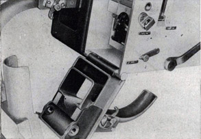
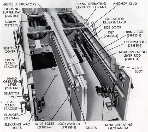
9. Removal and Disassembly of the Hand Operating Mechanism, Figure 85
The removal and disassembly of the hand operating mechanism necessitates the removal of the loader and the housing assemblies. The hand operating lever and both catch bracket assemblies may be removed without disturbing any of the other units.
a. Remove the hand operating lever.
(1) Remove the locking screw and tap out the retaining pin.
(2) Remove the hand operating lever.
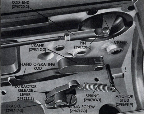
Figure 85
Interior of the slides.
127
b. Remove the hand operating rod, crank, and shaft.
(1) Remove the elastic stop nuts and the screws from the rear bracket.
(2) Remove the cotter pin, retaining nut, and the washer from the front crank.
(3) Move the hand operating rod, crank, and shaft inward toward the center of the slide and remove.
c. Disassemble the hand operating rod, crank, and shaft.
(1) Remove the cotter pins and the clevis pins and remove the crank and the rod.
(2) Remove the taper pin and pull the arm and bracket off the hand operating lever shaft.
d. Remove and disassemble the catch brackets.
(1) Remove the retaining screws and the catch bracket assemblies.
(2) To disassemble the catch brackets remove the seat, spring and the plunger from the bracket.
10. Assembly and Installation of the Hand Operating Mechanism
a. Assemble and install the catch brackets.
(1) Install the plunger (298724-4) and the spring (298724-5) in the bracket (298708-4), and the screw in the spring seat (298724-3).
(2) Install the catch bracket assemblies, and insert the retaining screws (3/8"-24 x 5/8").
b. Assemble the hand operating rod, crank, and shaft.
(1) Assemble the bracket (298713-2) and the arm (298713-1) on the hand operating lever shaft (298711-1) and secure the arm to the shaft with the taper pin (No. 0 x 1").
(2) Assemble the hand operating rod (298712-1) on the front crank (298712--2) and the hand operating lever shaft with the clevis pins (298712-4) and the cotter pins (1/8" x 3/4").
c. Install the hand operating rod, crank, and shaft.
(1) Insert the assembly, the slide, and push the hand operating lever shaft through its bushing in the side of the slide.
(2) Install the screws (298712-5) in the bracket, and put on the elastic stop nuts (3/8"-24).
(3) Install the washer (1/2") and the retaining nut (1/2"--20) on the front crank, and insert the cotter pin (1/8" x 1-1/4").
d. Install the hand operating lever.
(1) Install the hand operating lever (298714-1).
(2) Drive in the retaining pin (298712-3), and install the locking screw (1/4"-20 x 3/8").
128
11. Removal and Disassembly of the Trigger Mechanism
To remove and disassemble the trigger mechanism it is first necessary to remove the loader.
a. Loosen the firing lever assembly.
(1) Remove the firing lever spring stud.
(2) Unhook the trigger spring from the trigger and its stud.
(3) Remove the connecting screws and the firing lever spring.
b. Remove and disassemble the firing lever.
(1) Remove the lock screw, and tap the bearing pin out of the bracket.
(2) Remove the lever assembly from the slide.
(3) Remove the cotter pin, bearing pin, pawl, plunger, and the spring from the firing lever.
c. Remove the firing plunger and crank assembly.
(1) Remove the pivot pin, and dismount the crank assembly.
(2) Remove the firing plunger from the inside of the slide.
d. Disassemble the crank assembly.
(1) Remove the cotter pin, the clevis pin and the crank.
(2) Loosen both lock nuts, and remove the rod ends and lock nuts from the firing rod.
e. Remove the firing selector lever and the trigger.
(1) Remove the taper pin, the firing selector lever and the cam.
(2) The knurled head, the plunger, and the spring may be removed from the lever by grinding off the riveted end of the plunger. (3) Remove the taper pin, the bearing pin, and the trigger.
12. Assembly and Installation of the Trigger Mechanism
a. Install the firing selector lever and the trigger.
(1) Assemble the plunger (298701-2), the spring (298701-4), and the knurled head (298701-3) with the lever (298720-9).
(2) Install the cam (298708-3) through the side of the slide, and attach the firing selector lever with the taper pin (No. 00 x 1").
(3) Install the bearing pin (298699-5), the trigger (298727-2) and
drive in the taper pin (No. 000 x 3/4").
b. Assemble the crank assembly.
(1) Assemble the rod ends (298720-2) on the rod (298720-1), locking them with the lock nuts (1/4"-28).
(2) Attach the crank (298710-1) to the firing rod by means of the clevis pin (298720-6), and fasten with the cotter pin (1/16" x 1/2").
129
c. Install the crank assembly and firing plunger in the trunnion.
(1) Insert the firing plunger (298697-1) from the inside of the slide.
(2) Install the crank assembly and the pivot pin (298710-2).
d. Assemble and install the firing lever.
(1) Assemble the spring (298719-2), the plunger (298704-2), the pawl (298717-4), the bearing pin (298719-1), and the cotter pin (1/16" x 1") in the firing lever (298718-1).
(2) Place the assembly in the slide, and install the bearing pin (298704-3) in the bracket (298708-2). Install the lock screw (1/4"-20 x 1/2").
e. Attach the trigger mechanism springs and the firing rod.
(1) Install the firing lever spring (298720-5) and attach the firing rod with connecting screws (298693-5).
(2) Install the firing lever spring stud (298720-3) and the trigger spring stud (298699-6) and attach the trigger spring (298727-3) and the firing lever spring.
Figure 86
Detail of the interior of the slide.
130
13. Removal of the Extractor Release Lever
To remove or install the extractor release lever it is necessary to have the housing out of the slide.
a. Remove the extractor release lever, Figure 86.
(1) Unhook the spring from the lever and from the anchor stud.
(2) Remove the bracket retaining screws and remove the bracket, lever, and stud from the slide.
(3) Remove the cotter pin; unscrew the bearing screw, and remove the lever from the bracket.
14. Installation of the Extractor Release Lever
a. Install the extractor release lever.
(1) Assemble the lever (298717-1) on the bracket (298717-2) with the bearing screw (298717-3); lock with the cotter pin (1/8" x 1").
(2) Install the bracket and lever in the slide and insert the retaining screws (5/l6"-24 x 3/4").
(3) Install the anchor stud (298698-9) in the slide, and hook the spring (298703-3) between the stud and the lever.
15. Removal of the Buffer Pad
To remove and install the buffer pad, the housing and recoil cylinder must be removed from the gun.
a. Remove the buffer pad.
(1) Loosen or remove the six set screws on the outside of the slide.
(2) Remove the retaining screws and the buffer pad.
16. Installation of the Buffer Pad
a. Install the buffer pad (298720-8) and the retaining screws (298720-7).
b. Install and tighten the set screws (l/4"-20 x 1/2") on the outside of
the slide.
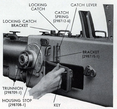
17. Removal of the Breech Block Locking Bolt Bracket and the Housing Stop
The breech block locking bolt bracket or the housing stop may be removed at any time without disturbing any of the other units.
a. Remove the locking bolt bracket.
(1) Remove the retaining screws, the spring, and the bracket.
b. Remove the housing stop.
(1) Remove the retaining screws, and pull the stop out of the side of the slide.
18. Installation of the Housing Stop and the Breech Block Locking Bolt Bracket
a. Install the housing stop.
(1) Mount the stop (298708-1) in position in the slide and install the retaining screws (3/8"-24 x 5/8").
131
b. Install the breech block locking bolt bracket.
(1) Locate the bracket (298715-1) on the side of the slide.
(2) Install the spring (298712-6) and insert the five retaining screws (No. 10-32 x 1/2").
G. SIGHT ASSEMBLY
The following instructions apply to either the Mark 3 or Mark 4 sight assembly.
1. Removal of the Sight Assembly
a. Remove the bolts and lockwashers which attach the arm weldment to the slides.
b. Remove the sight assembly.
c. Remove the dowel pins.
2. Installation of the Sight Assembly
a. Place the sight assembly in position and install the bolts
(1/2"-20 x 1") and the 1/2" external tooth lockwashers, turning the bolts down lightly.
b. Install the dowel pins (299277-4).
c. Tighten the bolts.
d. Check the alignment of sights as described in Chapter IV.
3. Disassembly of the Sight Assembly
The following instructions apply to either the pointer's or trainer's sight assembly.
a. Remove the sight guard weldment.
(1) Remove the lock nuts and bolts and lift off the sight guard weldment.
b. Remove and disassemble the pointer's and trainer's sight assemblies.
(1) Remove the lock nuts and bolts and remove the cap.
(2) Remove the assembly and tap out the key. (3) Remove the front sight.
(a) Remove the lock nuts and bolts and remove the front sight bracket.
(b) Lift out the front sight.
(c) Screw off the adjusting collar.
(d) Tap the taper pin out of the ferrule.
(e) Remove the ferrule from the bar.
132
(4) Remove the rear sight.
(a) Tap the taper pin out of the rear sight.
(b) Remove the rear sight from the bar.
(c) Remove the expansion plug from the bar.
4. Assembly of the Stripped Sight Assembly
a. Assemble and install the pointer's and trainer's sight assemblies.
(1) Install the rear sight.
(a) Insert the expansion plug (345897-259) in the sight bar (299350-1).
(b) Install the rear sight (299349-2) on the sight bar.
(c) Install the taper pin (No. 4 x 1-1/2").
(2) Install the front sight.
(a) Install the ferrule (299349-4) on the sight bar.
(b) Tap in the taper pin (No. 4 x 1-1/2").
(c) Screw the adjusting collar (299346-2) onto the front sight (299342-1).
(d) Locate the front sight with adjusting collar in the corresponding channels of the ferrule, with the keyway of the sight bar on the inboard side.
(e) Install the front sight bracket (299346-3).
(f) Install the bolts (3/8"-24 x 1-1/2"), the 3/8" flat washers, and lock nuts (3/8"-24).
(3) install the sight assemblies (299343-1, trainer's; 299343-2, pointer's) on the arm weldment (299344-1, Mark 3; 299345, Mark 4) with the key (299346-1) in the keyway.
(4) Install the cap (299350-2).
(5) Install the bolts (3/8"-24 x 1-1/4") and lock nuts (3/8"-24).
b. Install the sight guard weldment.
(1) Locate the sight guard weldment (345493) and bolt in place with the bolts (3/8"-24 x 2-3/4") and lock nuts (3/8"-24).