|
|
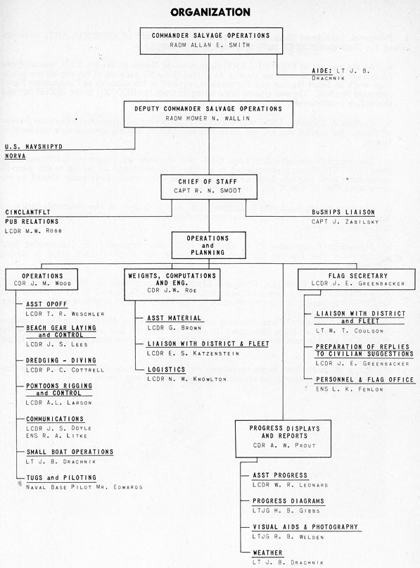
ORGANIZATION
ENCLOSURE 3
|
1
|
|
2
|
1. Personnel, outside of those attached to the regular staff of COMCRULANT, were obtained for their special skills and experience as follows:
|
a. At the request of COMCRULANT, Rear Admiral Homer N. Wallin, USN, was assigned temporary additional duty as Deputy to COMCRULANT because of his experience in salvage work at Pearl Harbor and for services required in his capacity as Commander Naval Shipyard Norfolk. He was aboard intermittently from the SECOND to the SIXTH day and thereafter continuously.
b. Captain J. Zabilsky, USN, was obtained on temporary additional duty from the Bureau of Ships. He headed the salvage section in that bureau and his services were employed in liaison.
c. Lieutenant Commander J. S. Lees, USN, was obtained on temporary additional duty from COMTHREE being experienced in salvage in general and in laying beach gear in particular. Both Captain Zabilsky and Lieutenant Commander Lees came aboard to observe but COMCRULANT put them to work.
d. Lieutenant Commander A. L. Larson, USN, was obtained on the recommendation of Rear Admiral Wallin from the Naval Ammunition Depot, Crane, Indiana, as experienced in rigging pontoons.
e. Lieutenant Commander P. C. Cottrell, USN, was obtained from Commander Submarine Base, New London, Connecticut, as coordinator of SUBLANT ships in diving operations.
f. Commander F. E. Wilson, USN, and Lieutenant Commander N. W. Knowlton, USN, were obtained on temporary additional duty from COMSERVLANT to act in liaison with that type commander and as coordinators of SERVLANT ships employed in the operation.
g. Pilot R. C. Edwards was obtained from the Naval Base, Norfolk, for his experience in handling tugs and ships alongside. In order to conserve time and space alongside the MISSOURI all ship captains were encouraged to use tugs to get alongside quickly or to get clear more quickly.
h. Mr. J. M. McFarland, when operations required, was obtained from Naval Supply Center, Norfolk, to coordinate the off-loading of ammunition and stores.
|
|
|
|
SHIPS AND FACILITIES
ENCLOSURE 4
|
1
|
|
SHIPS AND FACILITIES
I Ships
1. U. S. Army dredge COMBER was obtained through the Norfolk District U. S. Army Engineers. The COMBER was engaged in a routine channel maintenance job in Baltimore and upon official request by COMCRULANT was dispatched to the scene immediately by Army orders, arriving at 0820, 18 January. Through the same offices, services of necessary survey parties were obtained to provide accurate information on the results of dredging operations both alongside the ship and in the exit channel. These surveys were valuable in charting the progress of dredging and influenced our daily operations materially.
2. The commercial hydraulic dredge WASHINGTON was obtained by contract arranged through FIFTH Naval District Public Works Offices with the Norfolk Dredging Company. The WASHINGTON arrived on the scene at 1600, 21 January.
3. Ships obtained from COMSERVLANT are summarized as follows:
a. AMPHION (AR13) - Reported at 1900 Tuesday, 17 January, was anchored in the area and utilized for logistic purposes, repairs, and supplies. AMPHION also served as a boat pool to service and house boats and boat's crews. The AMPHION (AR13) is a large fleet repair ship capable of general overhaul and repair work for heavy combatant ships. This ship was especially helpful in fitting the three damaged double bottoms with covers to pressurize those tanks and blow them out and the considerable shoring of adjacent compartments that was necessary. Since these were fuel oil bottoms this was dirty work.
| b. ARS's |
HOIST (ARS40) |
- Reported 1100 Thursday, 19 January. |
| |
OPPORTUNE (ARS41) |
- Reported 1100 Thursday, 26 January. |
| |
RECOVERY (ARS43) |
- Reported 0700 Saturday, 28 January. |
ARS's are rescue salvage ships of some 1,360 tons displacement especially rigged for laying beach gear. They are particularly maneuverable for towing work being twin shaft vessels and developing 3,000 brake h. p.
| c. ATF's |
KIOWA (ATF72) |
- Reported 1751 Tuesday, 17 January. |
|
LUISENO (ATF156) |
- Reported 2130 Friday, 20 January. |
|
NIPMUK (ATF157) |
- Reported 1700 Tuesday, 31 January. |
|
MOSOPELEA (ATF158) |
- Reported 1420 Saturday, 21 January. |
|
PAIUTE (ATF159) |
- Reported 0509 Wednesday, 18 January. |
|
PAPAGO (ATF160) |
- Reported 1812 Tuesday, 17 January. |
|
ALSEA (ATF97) |
- Reported 1200 Tuesday, 17 January. |
ATF's are fleet tugs of some 1,280 tons displacement. They are single screw craft developing 3,000 brake h. p. They are also fitted with powerful pumps and other salvage equipment. These were released to COMSERVLANT when not needed.
| d. AO's |
CHEMUNG (A030) |
- Reported 1720 Tuesday, 17 January. |
|
PAWCATUCK (A0108) |
- Reported 2230 Tuesday, 17 January. |
The CHEMUNG and PAWCATUCK are fleet oilers of some 23,000 tons full load displacement. Their cargo capacity exceeds six million gallons.
| e. ARSD's |
WINDLASS (ARSD4) |
- Reported 0700 Thursday, 19 January. |
|
SALVAGER (ARSD3) |
- Reported 0700 Thursday, 19 January. |
ARSD's are salvage vessels designed primarily for lifting. They have winches capable of producing 150 tons and can utilize this power either vertically by flooding and then pumping out, or horizontally by pulling against heavy beach gear anchors which are a part of the regular equipment. These ARSD's have a standard displacement of 816 tons.
|
2
|
4. Ships obtained from COMSUBLANT:
| ASR's |
CHANTICLEER (ASR7) |
- Reported 0900 Thursday, 19 January. |
|
KITTIWAKE (ASR13) |
- Reported 1708 Tuesday, 17 January. |
|
PETREL (ASR14) |
- Reported 1513 Monday, 23 January. |
|
TRINGA (ASR16) |
- Reported 1640 Tuesday, 24 January. |
ASR's are submarine rescue vessels of some 1,780 tons displacement with single screw and developing 3,000 brake h. p. They are equipped with powerful pumps, heavy air compressors, high pressure hoses with lances, and special submarine rescue chambers in addition to all the necessary equipment for tending divers.
5. Ships obtained from COMNAVBASENORVA included ATA's (1500 h. p. auxiliary tugs) and YTB's (900 h. p. diesel harbor tugs) in numbers as required for general service, at least two YTBs' remaining at the scene of salvage at all times. In addition, yard oil barges and water barges were available on call for off-loading and on-loading fluids. Ammunition barges and floating crane service were also provided on call for off-loading ammunition.
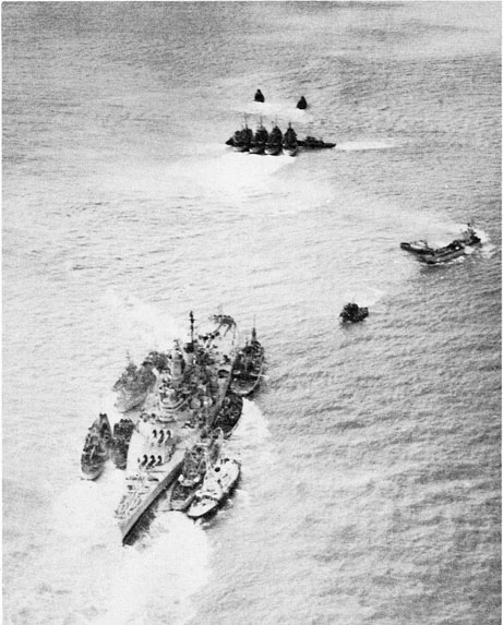
6. COMDESLANT was requested to and did provide three destroyers to be used if necessary as a unit for making bow waves on the occasion of any pull-off attempt. Although never employed, it became apparent from rehearsals conducted on Tuesday, 31 January, that their effect might be quite valuable and they were retained on a standby basis with plan already outlined for the task when directed. Due to the probability of carrying away some towing lines, and damage to ships lashed together the destroyers were scheduled to make their first run at 10 minutes past high water, so that casualties would not prevent the initial full coordinated pull. The MISSOURI was refloated before the time scheduled for the destroyers' run.
7. These ships were employed in detail as outlined in the Daily Log - Enclosure 13.
II Facilities
8. Immediately after COMCRULANT went aboard the MISSOURI, 17 January, the ship's Communications Officer was instructed to establish routing and handling procedures for staff communications traffic. Two voice circuits, FIFTH Naval District Tug and the Fleet Common Primary were available and used to the greatest extent possible. The Fleet Common Primary circuit terminal in the FIFTH Naval District Headquarters was manned by staff personnel on 17 January with telephone relay service to the staff duty officer ashore immediately available. The circuit was later restricted to use for salvage operations and its use facilitated voice traffic to a very great extent. On 19 January, COMCRULANT staff Communications Officer took control of communications in MISSOURI and introduced refinements in distribution procedures to speed up the delivery of messages. On 22 January a duplex RATT system was established between MISSOURI and the FIFTH Naval District which further increased the facility with which messages could be sent and received. On 23 January a separate flag communications office was established in Flag Plot. In order to maintain continuity of files, all messages originated by the staff in MISSOURI were sent to COMCRULANT Administration for information.
9. Another very important service rendered to MISSOURI was the furnishing of fire main pressure by ships alongside. Due to clogged injections MISSOURI was unable to obtain sufficient suction to utilize main generator condensers and provide adequate fire main and flushing pressure. Additional pressure was first furnished by KIOWA about noon 17 January. At about 1700 that date, KITTIWAKE, because of more powerful pumps, took over the chore. A SR's continued this service with only minor interruptions until MISSOURI was refloated. Security measures against fire were always ready at hand and some fire drills were held.
|
3
|
|
10. Transportation - LSI's were made available by COMNAVBASENORVA for transportation of working parties and other miscellaneous requirements on a two hour schedule, from 0700 to 1700 daily. One scheduled round trip was made at 2400 daily and an LSI was always available at the Naval Base between the hours of 1700 and 0700 for emergency use. Motor Torpedo Boat Squadron ONE was made available by COMOPDEVFOR for ferry trips to and from the ship. These boats, based at the Naval Base, were available on 15 minutes notice throughout the day and 45 minutes notice during the hours of darkness. Three LCPL's were made available by Commander Amphibious Training Command. These small boats, manned by crews from the MISSOURI, were used at the scene of the grounding for general utility and transportation between ships.
11. Through the FIFTH Naval District, the services of the Coast Guard were obtained for patrolling the adjacent main ship channel when needed, and for placing buoys to be used as ranges for the dredged channel. Also through the FIFTH Naval District, liaison was obtained with the Public Works Department, Coast and Geodetic Survey and Fort Monroe, all of whom provided accurate tidal data on an hourly basis in the second week.
|
|
|
BEACH GEAR
ENCLOSURE 5
|
1
|
|
BEACH GEAR
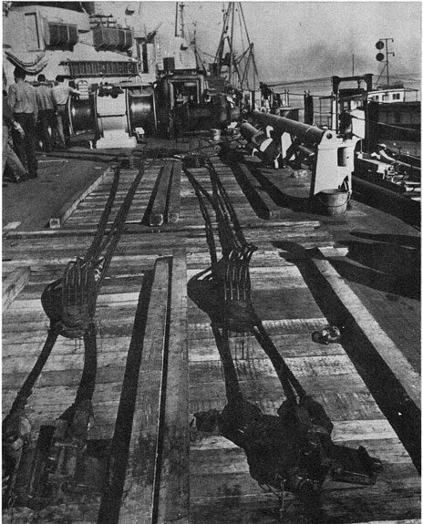
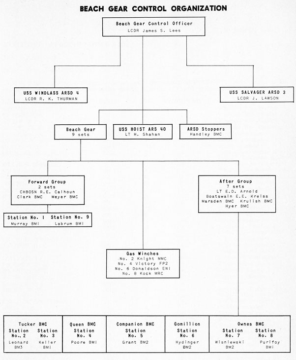
1. When it became apparent that the MISSOURI could not be refloated by the use of tugs alone, it was decided to assemble, in the Norfolk area, sufficient sets of Beach Gear to accomplish the task. Based on initial calculations it was determined that by providing for additional buoyancy through use of "Structural" Submarine Rescue Pontoons and the removal of weights such as fuel, ammunition, anchors, water and stores, nine (9) sets of Beach Gear used in conjunction with available tugs could generate sufficient line pull to overcome the ground reaction remaining on the planned date for removal from the strand. Each set of gear laid was standard except for the second anchor and consisted of:
|
a. Crown buoy and recovery wire.
b. Two 4 ton Eells anchors.
c. 15 fathoms shot of 2 1/4" chain.
d. 250 fathoms of 1 5/8" 6 x 37 H. G. P. S. wire.
e. Set of 4 fold blocks rove off with 1200' of 5/8" wire rope.
f. Two 1 5/8" carpenter stoppers.
g. 4 plate shackles for connecting wires, chain and anchor.
h. Portable gas driven winches with 7.5 tons line pull where ship's power was not available.
i. Two 5/8" and one 1 5/8" fairlead block.
|
2. By 18 January 1950 a survey of qualified personnel, the MISSOURI's deck plan, and sets of Beach Gear available in the stranding or other immediate areas had been made. This study showed that in the Norfolk vicinity thirteen sets were available; seven (7) sets on Atlantic Fleet Tugs and six (6) on the HOIST. A reserve of twelve (12) sets at the salvage pool, maintained by the Bureau of Ships in ready storage at the Naval Supply Depot in Bayonne, N. J. could also be obtained. The personnel check revealed that, while a limited number of persons qualified to rig, plant and operate Beach Gear with safety were available, they were insufficient, not fully qualified for the task at hand or were required on the vessel to which assigned. Accordingly LCDR J. S. LEES from the office of "Supervisor of Salvage U. S. N." RM1811, 17 Battery Place, N. Y. C. was assigned T. A. D. on the Staff, and designated as "Beach Gear Control Officer". Two officers and seven enlisted personnel were received from the U. S. Naval School (Salvage) to assist. Layout of the MISSOURI deck plan was predicated on the following considerations:
|
a. That the maximum amount of pulling force be exerted in the desired direction by use of Tugs and Beach Gear.
b. That the stranded vessel be under control when refloated.
c. That an ASR would be required alongside aft to provide air to pontoons being rigged under the stern.
d. That maximum use of the ship's deck machinery be made and that proper space for portable winches be available.
e. That three towing hawsers would be passed to the stern and others would be passed from vessels alongside.
f. That holding points be available, capable of withstanding at least the 100 tons pull expected from each of the SALVAGER and the WINDLASS. (This was accomplished by rigging bridles in a manner that the opposing forces involved were in effect against each other).
g. That each Beach Gear be clear of the others insuring insofar as possible the utmost in safety and maximum in efficiency yet clear of other evolutions.
|
|
2
|
3. To provide for a reserve of equipment the SALVAGER was directed to proceed to Bayonne, N. J. and obtain from the N. S. D. six sets of Beach Gear, portable winches and other salvage equipment that might be required. To obviate the difficulties of handling large amounts of this equipment in the limited space available on SALVAGER or associated type vessels, pier space was requested from the Naval Base Norfolk and assigned as a salvage pool from which the ARS type could operate and in which the ATF's could land their equipment. When the pier was ready, the ATF's were directed to land their equipment and the HOIST was assigned the task of sorting and preparing for use all such equipment, rigging and planting of the majority of sets required. A list of items necessary to rig the MISSOURI was prepared and a large proportion of it was delivered on board the afternoon of 23 January, the remainder was enroute from Bayonne and delivered alongside by ATF on the 24th. The salvage plan called for preparing MISSOURI and commencement of laying gears on Wednesday 25 January. However due to the multitudinous operations in process, progress of each was not consonant and the Beach Gears were planted as follows:
|
Vessel |
Date of Jan. 1950 |
| No. 1 |
RECOVERY (ARS 43) |
29th |
| No. 2 |
HOIST (ARS 40) |
28th |
| No. 3 |
RECOVERY (ARS 43) |
28th |
| No. 4 |
OPPORTUNE (ARS 41) |
28th |
| No. 5 |
HOIST (ARS 40) |
28th |
| No. 6 |
HOIST (ARS 40) |
28th |
| No. 7 |
OPPORTUNE (ARS 41) |
28th |
| No. 8 |
HOIST (ARS 40) |
28th |
| No. 9 |
HOIST (ARS 40) |
29th |
| Bow moorings (2) |
HOIST (ARS 40) |
27th |
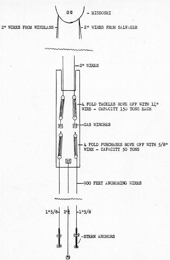
As soon as each gear was laid its station crew was instructed as to the part their gear was expected to play. the tons line pull their set would generate, casualties that might be anticipated and the most expeditious and safest method for releasing and casting overboard the wires when the MISSOURI refloated. SALVAGER and WINDLASS, rigged as shown on appendix (E), moved into assigned position on 28 January. Their 2" wires were run by the YTB 365 on the 29th. These two inch wires were ATF towing hawsers obtained from ComServLant especially for this operation inasmuch as it was desirable that the two vessels be clear of the Beach Gear wires during the hauling operation and at least 400 yards from the MISSOURI in order to provide a good catenary. The 10,000 pound anchors used in the stern moorings of these vessels were "Danforth type" and loaned to the Navy by the Danforth Anchor Co. of Buffalo, N. Y. especially for this operation.
4. The planning and rigging phases were completed on the 30th without insurmountable difficulties and the final layout was as envisaged in the original salvage plan.
5. The operational phase commenced in the early morning of the 31st when a Coordination Rehearsal was held and an attempt to "Pull Off" was made. During the rehearsal some material but no mental failures were observed. The material deficiencies were:
|
a. Clutch slipping on #6 winch.
b. Failure of pipe stanchions on lip of waterway permitted wire of No. 3 beach gear to jump outboard and become entangled with No. 2 gear. As a result of this failure one beach gear was ineffective during latter part of rehearsal.
c. Poor lead for No's 3 and 7 wires.
|
All deficiencies were corrected that date. Stopper releasing and casualty drill held and all was in readiness for "Pull Off". Lessons were learned and confidence gained from the rehearsal run and as a result of this it was felt that a very effective force was ready for application.
|
3
|
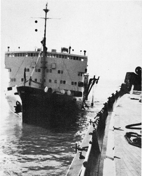
6. On the 1st of February 1950, Beach Gear stations were manned at 0530 and the Haul Off Plan, appendices (D) and (E) to enclosure 13 were put in effect. This plan was most effective and about 0644 there was indication of lateral movement and about 0700 some astern movement. At 0709 it was possible to report "the ship is definitely moving astern". Accordingly permission was requested to cast off all Beach Gear wires, the SALVAGER and WINDLASS. The Recovery Plan was placed in effect immediately. During the haul off operations sets No. 1 and 6 carried away. This carrying away was not as a result of poorly designed or improper equipment. The 1 5/8" wires with a nominal breaking strain of 90 tons were pulled apart by the tremendous force applied to them.
| APPENDIX (A) |
- Deck Arrangement of Beach Gear Tackles as Employed in Refloating Operation. |
| APPENDIX (B) |
- Position of Beach Gear and Tugs, 1 February 1950. |
| APPENDIX (C) |
- Beach Gear Control Organization. |
| APPENDIX (D) |
- U. S. S. MISSOURI Beaching Gear Stations. |
| APPENDIX (E) |
- Deck Arrangement SALVAGER and WINDLASS on 1 February 1950. |
|
4
|
|
This page is blank.
|
5
|
Page 5, Appendix A.
USS MISSOURI
Deck Arrangement of Beach Gear Tackles As Employed in Refloating Operation
Hampton Roads, 1 February 1950
5 Appending (A) To Enclosure 5
(Large image is on separate page.)
|
6
|
|
This page is blank.
|
7
|
Page 7, Appendix B.
Position of Beach Gear and Tugs, 1 February, 1950
7 Appending (B) To Enclosure 5
(Large image is on separate page.)
|
8
|
|
This page is blank.
|
9
|
|
10
|
|
UNITED STATES ATLANTIC FLEET
U. S. S. MISSOURI
23 January 1950
EXECUTIVE OFFICER'S NOTICE 5-50:
To: All Hands
Subj: Beach Gear Stations.
1. The following station assignments are made for scheduled PULLOFF. No changes of below assigned personnel will be made except by order of the First Lieutenant.
| NAME |
RATE |
DIV. |
STATION NO. |
DUTY |
| CHRISTIAN, C. L. |
SN |
5 |
2 |
Windlass line handler |
| BRACKEEN, S. |
SN |
5 |
2 |
Windlass line handler |
| DUX, F. J. |
SN |
5 |
2 |
Windlass line handler |
| DOOLEN, T. J. |
SN |
5 |
2 |
Windlass line handler |
| BROOKS, H. N. |
SN |
5 |
2 |
Carpenter stoppers |
| COOPER, G. E. |
SN |
5 |
2 |
Carpenter stoppers |
| BAKER, G. R. |
EN1 |
"A" |
2 |
Winch operator |
| LEONARD, G. P. |
BM3 |
5 |
2 |
In charge of station & 51-54JY Telephone talker |
| ENS R. H. SPRINCE |
|
|
2 |
1JV Telephone talker |
| MILES, J. L. |
SN |
5 |
3 |
Windlass line handler |
| THOMPSON, A. |
SA |
5 |
3 |
Windlass line handler |
| GRIFFIN, Q. E. |
SA |
5 |
3 |
Windlass line handler |
| MCLANE, M. L. |
SN |
5 |
3 |
Windlass line handler |
| DYER, G. C. |
GM3 |
5 |
3 |
Carpenter stoppers |
| CALLAGHAN, |
SN |
5 |
3 |
Carpenter stoppers |
| DUNCAN, R. E. |
EM3 |
"E" |
3 |
Winch electrician |
| HALL, J. T. |
SN |
5 |
3 |
Hook operator |
| HALL, C. |
BM3 |
5 |
3 |
Winch operator |
| KELLER, C. E. |
BM2 |
5 |
3 |
In charge of station & 51-54JY Telephone talker |
| ENS R. H. SPRINCE |
|
|
3 |
1JV Telephone talker |
| SANDRIB, P. A. |
SN |
7 |
4 |
Windlass line handler |
| PAGANO, J. S. |
SA |
7 |
4 |
Windlass line handler |
| LOPRESTI, P. |
SA |
7 |
4 |
Windlass line handler |
| REFFETT, R. L. |
SA |
7 |
4 |
Windlass line handler |
| MANNING, E. J. |
SN |
7 |
4 |
Carpenter stopper |
| MORELAND, H. J. |
SA |
7 |
4 |
Carpenter stopper |
| LAWRENCE, A. A. |
EN2 |
"A" |
4 |
Winch operator |
| MOORE, W. W. |
BM1 |
7 |
4 |
In charge of station & 51-54JY Telephone talker |
| ENS E. M. ZACHARIAS |
|
|
4 |
1JV telephone talker |
| BELL, C. R. |
SN |
3 |
5 |
Capstan operator |
| GRANT, G. C. |
BM2 |
3 |
5 |
Windlass line handler |
| SIEDSCHLAG, R. C. |
SN |
3 |
5 |
Windlass line handler |
| CARTWRIGHT, W. H. |
SN |
3 |
5 |
Windlass line handler |
| LAKE, H. |
SN |
3 |
5 |
Windlass line handler |
| HARMAN, W. G. |
BM3 |
3 |
5 |
Carpenter stopper |
| MORRIS, W. H. |
SN |
3 |
5 |
Carpenter stopper |
| FETTERMAN, F. C. |
EM3 |
"E" |
5 |
Capstan electrician |
| COMPANION, R. B. |
BMC |
3 |
5 |
In charge of station & 51-54JY Tele. talker |
| ENS C. MERTZ |
|
|
5 |
1JV Telephone talker |
| PERSONIOUS, D. G. |
SN |
6 |
6 |
Windlass line handler |
| MCCULLUM, B. N. |
SN |
6 |
6 |
Windlass line handler |
| BROWN, R. |
SN |
6 |
6 |
Windlass line handler |
| DOUGHERTY, W. G. |
SN |
6 |
6 |
Windlass line handler |
| MESQUIHT, A. M. |
SN |
6 |
6 |
Carpenter stopper |
| HEINE, D. H. |
SN |
6 |
6 |
Carpenter stopper |
|
12
|
| NAME |
RATE |
DIV. |
STATION NO. |
DUTY |
| BURKE, E. L. |
SN |
6 |
6 |
Carpenter stopper |
| HOLIFIELD, W. D. |
SN |
6 |
6 |
Carpenter stopper |
| SWANEY, C. J. |
EN2 |
"A" |
6 |
Winch Operator |
| HYDINGER, L. D. |
BM2 |
6 |
6 |
In charge of station & 51-54JY Tele. talker |
| LTJG E. C. KLINE |
|
|
6 |
1JV Telephone talker |
| VALDEZ, L. |
SN |
4 |
7 |
Windlass line handler |
| CHAVEZ, C. |
SN |
4 |
7 |
Windlass line handler |
| STARKE, R. E. |
SN |
4 |
7 |
Windlass line handler |
| DUPREE, E. H. |
SN |
4 |
7 |
Windlass line handler |
| SENDLAK, R. E. |
SN |
4 |
7 |
Carpenter stoppers |
| FAULHABER, E. F. |
SN |
4 |
7 |
Carpenter stoppers |
| HELMLY, R. L. |
EM2 |
"E" |
7 |
Winch electrician |
| RAINES, R. E. |
SN |
4 |
7 |
Winch Operator |
| WISNIEWSKE, B. J. |
BM3 |
4 |
7 |
In charge of station & 51-54JY Tele. talker |
| ENS R. W. O'REILLY |
|
|
7 |
1JV Telephone talker |
| PEARLMAN, A. A. |
SN |
4 |
8 |
Windlass line handler |
| ROE, F. 0. |
SN |
4 |
8 |
Windlass line handler |
| GNALL, G. K. |
SN |
4 |
8 |
Windlass line handler |
| HAILEY, J. W. |
SN |
4 |
8 |
Windlass line handler |
| COLE, C. T. |
SN |
4 |
8 |
Carpenter stopper |
| LIPPS, R. H. |
SN |
4 |
8 |
Carpenter stopper |
| LATTANZI, V. L. |
EN2 |
"A" |
8 |
Winch operator |
| PURIFOY, W. H. |
BM1 |
4 |
8 |
In charge of station & 51-54JY Tele. talker |
| ENS R. W. O'REILLY |
|
|
8 |
1JV Telephone talker |
| PATTERSON, J. F. |
SN |
2 |
9 |
Windlass line handler |
| SILSBY, B. H. |
SN |
2 |
9 |
Windlass line handler |
| MARTIN, N. F. |
SN |
2 |
9 |
Windlass line handler |
| MARIORENZI, A. R. |
SN |
2 |
9 |
Windlass line handler |
| CAVANAUTH, J. V. |
SN |
2 |
9 |
Carpenter stopper |
| HOWARD, M. R. |
SN |
2 |
9 |
Carpenter stopper |
| ALTIZER, H. A. |
SN |
2 |
9 |
Carpenter stopper & hook rope |
| WALTERS, D. W. |
SA |
2 |
9 |
Carpenter stopper & hook rope |
| COLEN, E. W. |
ME1 |
"R" |
9 |
Capstan operator |
| MAXSON, S. W. |
ME3 |
"R" |
9 |
Capstan operator |
| LABRUM, F. L. |
BM1 |
2 |
9 |
In charge of station & 51-54JY Tele. talker |
| LTJG R. A. CRESSMAN |
|
| 9 |
1JV Telephone talker |
| GORINE, J. S. |
SN |
1 |
1 |
Windlass line handler |
| WALLACE, F. T. |
SN |
1 |
1 |
Windlass line handler |
| EUDY, L. C. |
SA |
1 |
1 |
Windlass line handler |
| SHIHINSKY, M. |
SA |
1 |
1 |
Windlass line handler |
| BERNIER, J. P. |
SN |
1 |
1 |
Carpenter stopper |
| MUGFORD, D. |
SN |
1 |
1 |
Carpenter stopper & hook rope |
| VARGA, M. |
SN |
1 |
1 |
Carpenter stopper & hook rope |
| HERRING, M. W. |
SN |
1 |
1 |
Carpenter stopper & hook rope |
| WESTENIUS, R. C. |
EM2 |
"E" |
1 |
Capstan electrician |
| MORIN, L. H. |
ME2 |
"R" |
1 |
Capstan operator |
| BURGESS, G. L. |
ME3 |
"R" |
1 |
Capstan operator |
| MURRAY, |
BM1 |
1 |
1 |
In charge of station & 51-54JY Tele. talker |
| EDGAR, C. L. |
FN |
"R" |
1 |
Capstan telephone talker |
| LTJG R. J. HANLEY |
|
|
1 |
1JV telephone talker |
2. Station numbers of beach gear commence at frame 23 starboard and run clockwise. The 51-54JY will be tied together and used as the special circuit for telephone communications to the beach gear stations. The 1JV circuit will be for direct communications with CONN and beach gear stations.
|
13
|
3. Personnel assigned to beach gear stations will be used to handle and set up their respective beach gear as it is brought aboard. They will be made available by respective departments as required. The beach gear will commence arriving at 0800 Monday 23 January.
/s/ G. E. PECKHAM
Commander, U. S. Navy,
Executive Officer
|
Copy to:
ComCruLant
LCDR J. S. LEES (10)
|
14
|
|
This page is blank.
|
15
|
|
Deck Arrangement Salvager and Windlass on 1 Feb. 1950
|
|
|
DREDGING
ENCLOSURE 6
|
1
|
|
DREDGING
1. The tasks for the COMBER were assigned as follows:
|
a. Dredge an exit channel from immediately astern of the MISSOURI to deep water, a distance of approximately 1,800 feet, through which the MISSOURI would pass on her way to the main channel. The exit channel was to be parallel to the MISSOURI's longitudinal centerline plane extended, to extend 75 feet each side of the centerline and to be 40 feet deep at a 2.7 foot tide.
b. Dredge a trench on each side of and parallel to the MISSOURI and as close to each side as possible. These trenches were to be 40 feet deep at a 2.7 foot tide and of sufficient width to allow the depth to be attained. These trenches were to provide ditches into which the sand under the ship would be sloughed by pressure of the ship on the ground, by the action of the current, and by diver's tunnelling operations.
|
2. The tasks for the Washington were assigned as follows:
|
a. Dredge that portion of the exit channel from the MISSOURI's stern to about 250 aft which the COMBER could not dredge.
b. Dredge to a 40 foot depth at a 2.7 foot tide from the inboard side of the trench made on each side of the MISSOURI by the COMBER to the side of the MISSOURI and under the ship if and where possible. This was to be done from amidships on one side aft, around the stern and up to amidships on the other side. This was to further augment the sloughing of the sand from under the bottom as described in paragraph 1 b. above. Around the stern the dredging was to prevent damage to the propellers and rudders during the first few feet of pull off, until they passed into the dredged exit channel.
|
3. The requirement for the dredged exit channel was reduced to 35 feet as the operation progressed.
4. Summaries of the COMBER's and Washington's operations are included as appendices (A) and (B) respectively. Appendix (C) is a chart of the soundings in the exit channel just prior to the pull off.
APPENDIX (A) - Tabular Summary of the Operations of the U. S. Army Dredge COMBER.
APPENDIX (B) - Tabular Summary of the Operations of the Norfolk Dredging Company's Dredge Washington.
APPENDIX (C) - Chart of Soundings in Exit Channel.
|
2
|
|
This page is blank.
|
3
|
TABULAR SUMMARY OF THE OPERATIONS OF THE
U. S. ARMY DREDGE COMBER
|
| Cubic Yards Removed |
| Date |
Time |
Port |
Starboard |
Exit
Channel |
Hours |
| 18 |
0820-1250 |
2,417 |
- |
4,833 |
4.5 |
|
1335-1807 |
6,447 |
- |
- |
4.5 |
|
1829-2400 |
- |
- |
5,565 |
5.6 |
| 19 |
0018-0805 |
- |
- |
9,015 |
7.78 |
|
0830-1944 |
- |
12,720 |
- |
11.23 |
|
2010-2400 |
- |
- |
4,561 |
3.83 |
| 20 |
0000-0635 |
- |
- |
7,676 |
6.58 |
|
1755-2400 |
7,041 |
- |
- |
6.08 |
| 21 |
0000-2400 |
23,995 |
- |
- |
24 |
| 22 |
0000-0555 |
9,191 |
- |
- |
5.92 |
|
1012-2400 |
- |
- |
17,275 |
13.8 |
| 23 |
0000-0655 |
- |
- |
8,991 |
6.92 |
|
0745-2400 |
- |
13,914 |
- |
16.25 |
| 24 |
0000-0720 |
- |
9,556 |
- |
7.33 |
|
0755-2400 |
- |
- |
15,685 |
16.08 |
| 25 |
0000-2400 |
- |
- |
22,078 |
24 |
| 26 |
0000-2350 |
- |
- |
18,150 |
23.83 |
| 27 |
0040-2400 |
- |
- |
16,484 |
20 |
| 28 |
0000-2400 |
- |
- |
8,848 |
24 |
| 29 |
0000-1720 |
- |
- |
8,372 |
17.33 |
|
TOTALS |
49,091 |
36,190 |
148,533 |
249.56 |
|
4
|
|
This page is blank.
|
5
|
TABULAR SUMMARY OF THE OPERATIONS OF THE
NORFOLK DREDGING COMPANY'S DREDGE WASHINGTON
|
|
Cubic Yards Removed |
| Date |
Time |
Port |
Starboard |
Exit
Channel |
Hours |
| 21 |
1900-2400 |
- |
- |
1,040 |
5 |
| 22 |
0000-2400 |
- |
- |
5,000 |
24 |
| 23 |
0000-1100 |
- |
- |
2,295 |
11 |
|
1200-2400 |
2,500 |
- |
- |
12 |
| 24 |
0000-2400 |
5,000 |
- |
- |
24 |
| 25 |
0000-0100 |
209 |
- |
- |
1 |
|
1330-1922 |
- |
1,225 |
- |
5.87 |
|
2150-2400 |
- |
452 |
- |
2.17 |
| 26 |
0000-0508 |
- |
1,070 |
- |
5.13 |
|
0623-1000 |
- |
755 |
- |
3.62 |
|
1100-2400 |
- |
- |
3,790 |
13 |
| 27 |
0000-0730 |
- |
- |
2,185 |
7.5 |
| 29 |
0830-2400 |
- |
- |
4,525 |
15.5 |
| 30 |
0000-1015 |
- |
- |
2,985 |
10.25 |
|
TOTALS |
7,709 |
3,502 |
21,820 |
140.04 |
|
6
|
|
This page is blank.
|
7
|
Page 7, Appendix C.
Chart of Soundings in Exit Channel
30 January 1950
7 Appending (C) to Enclosure 6
(Large image is on separate page.)
|
|
|