In this online version of the manual we have attempted to keep the flavor of the original layout while taking advantage
of the Web's universal accessibility. Different browsers and fonts will cause
the text to move, but the text will remain roughly where it is in the original
manual. We have not attempted to correct any errors found in the original document. However, this text was captured by optical character recognition and then encoded for the Web which has added new errors we wish to correct.
I apologize for the uneven quality of the photographs of the plates. Esp. the missing pages 12-13, and 34-35. I also need the text under the change notice on pages 9 and 27. Please report any typos, or particularly annoying layout issues to the Mail Feedback Form for correction.
Richard Pekelney
Webmaster
B.R. 901/43
HANDBOOK
OF THE
ADMIRALTY FIRE CONTROL CLOCK
MARKS I AND 1*
1943
ADMIRALTY, S.W.1.
Gunnery Branch
iii
ADMIRALTY, S.W.1.
16th September, 1943.
G. 3338/43.
B.R. 901/43. Handbook of the Admiralty Five Control Clock-Marks I and I*, 1943, having been approved by My Lords Commissioners of the Admiralty, is hereby promulgated for information and guidance.
B.R. 901 (formerly C.B. 1886/38). Handbook of the Admiralty Fire Control Clock-Mark I is hereby cancelled and all copies should be disposed of in accordance with the instructions in B.R. 1-Books of Reference and I.D. Catalogue.
By Command of their Lordships,
To Flag Officers and Commanding Officers of all H.M. Ships and Vessels concerned.
1. Layout of fire control installation-"Q" and "R" class destroyers. 2. Arrangement of bearings drives. 3. Arrangement of deflection shafting. 4. Arrangement of range shafting. 5. P.I.L. links showing the triangles formed. 6. Special range spotting dials for use with bombardment charges. 7. Reversible motor and relays and time of flight circuits. 8. Deflection factors. 9. Range correction factors. 10. Ballistic correction factors. 11. Time of flight. 12. Fudging of dip curve at low ranges. 13. Upper portion of range to elevation curve. 14. Equivalent full charge range (sub-calibre and reduced charge). 15. Deflection and range correction factors (sub-calibre). 16. Deflection and range correction factors (reduced charge). 17. A.F.C.C. I* Deflection factors (full and reduced charge). 18. A.F.C.C. I* Range correction factors (full and reduced charge). 19. A.F.C.C. I* Time of flight (full and reduced charge). 20. A.F.C.C. I* Fudging of dip curve at low ranges.
PLATES.
1. General diagrammatic arrangement. 2. Top of the clock. 3. Own, enemy and wind elements-speed settings. 4. Own, enemy and wind elements-bearing settings. 5. Speed across slides, deflection link, and gun range shafting. 6. Deflection dial and gun deflection shafting. 7. Drift link and drift relay. 8. Transmitter gearbox. 9. Cross levelling gear. 10. Speed along slides. 11. Range rate clock and clock range shafting. 12. Range correction links and ballistic settings. 13. Range P.I.L. follower and range spotting dials. 14. Range to elevation gear and gun range stop gear. 15. Gun elevation hunter and dip cam. 16. Gun elevation repeat receiver and Radar range matching receiver. 17. Time of flight clock. 18. Timing shafting. 19. P.I.L. gear. 20. Electrical diagram. 21. A.F.C.C. I and A.F.C.C I* wiring diagram arrangement of clock and relay.
(SO 2214) A 3
Admiralty Fire Control Clock Mark I
Frontpiece - To face page 1
1
PREFACE.
The A.F.C.C. I and I* are identical except that the former is made for the 4.7-inch Marks IX and XII, and is in all of fleet destroyers ("C" class and later except "L" and "M" class) and the latter is made for 4.7-inch Mark XI, and is in "L" and "M" class of destroyers only.
In consequence this Handbook is written for the A.F.C.C. I and the differences in the A.F.C.C. I* noted where they occur. (All gear ratios in the Plates are for A.F.C.C. I only.)
The following points about the contents of this Handbook should be noted:-
Chapter I (General description) is intended to be read by all officers and men who may be required to work the clock.
Chapter II (Reduced charge, sub-calibre and bombardment arrangements) gives the reduced charge and sub-calibre arrangements which vary slightly in different clocks.
Chapters III to VI. These chapters are for the use of officers and maintenance staffs for the initial adjustments and maintenance of the clock.
Chapter VII (Theory). This chapter compares the clock values with the theoretical values, and also gives the mathematics of the P.I.L. mechanism.
The Appendices, Diagrams and Plates are referred to in the text and are listed in the contents.
For all drills and procedures with the clock and associated H.A. and L.A. equipments, see separate Drill Book.
It should be noted that the A.F.C.C. referred to in this Handbook is fitted with cross levelling unit, Radar (including range matching receiver and clock range transmitter) and range correction indicator, and that these were not fitted in the original clocks.
FOOTNOTE.-in conformity with the decision made in 1943 the terms "Line of Sight Training" and "Director Setting" should in future be known as "Director Training" and "Director Elevation." The old terms which were printed on the Plates have been used throughout this book.
(S02214) A4
3
CHAPTER I.
GENERAL DESCRIPTION. See also Appendices I and II.
The Fire Control Installation.
1. The installation for which the clock is designed consists of:
(i) The director control tower, containing the control and rate officer, the director sight, and the cross levelling gear.
(ii) The transmitting station, containing the A.F.C.C. and F.K.C.
(iii) Radar Type 285 and a rangefinder fitted on a rangefinder director or three man rangefinder.
A typical installation is shown in Diagram 1.
The director transmits to the clock the bearing of the target relative to the fore and aft line of own ship-called line-of-sight training (L.S.T.)-and, at the moment of firing, the elevation of the. target relative to the deck plane of the ship-called director setting (D.S.)-corrected for the tilt of the D.C.T. (See Footnote on page 1.)
Uses of the Clock.
2. The clock performs the following operations:-
(i) Calculates the DEFLECTION due to own ship, enemy and wind, and provides a means of adding these and applying deflection spotting correction to give GUN DEFLECTION.
(ii) Transmits GUN TRAINING to the guns. Gun training is the sum of line of sight training, gun deflection (deflection plus deflection spotting), drift and cross levelling correction (or for H.A. fire, line of sight training, and total training correction transmitted from the fuze keeping clock). Convergence is corrected for at the training receivers at the guns.
(iii) Applies rate of change of range to the range set.
(iv) Calculates the range corrections for enemy, wind and ballistics, and provides a means of adding these and applying range spotting correction to give GUN RANGE.
(v) Calculates the tangent elevation, plus dip (from the director to the standard level) necessary for this range and adds it to the director setting, giving GUN ELEVATION which is transmitted from the clock to the guns. Dip (from the standard level to the guns), alterations in M.V. due to wear, and tilt are corrected for at the elevation receivers at the guns.
(vi) Transmits gun deflection and gun range to the guns for gunlayers and quarters firing. (Gun deflection does not include drift-see (i) above-and this is corrected for at the gunsights.)
(vii) Provides means for accurate calculation of P.I.L. correction to datum range and datum bearing. Also for application of range P.I.L. to datum range.
(viii) Incorporates a Time-of-Flight unit automatically set for range, and set by hand to the mean M.V. of all guns.
Settings required on the Clock.
3. Of the data required to set the clock, the following are automatically set:-
(i) Ship's head from gyro compass.
(ii) L.S.T. from D.C.T.
(iii) Director setting from D.C.T.
(iv) Cross-levelling from cross-levelling gear in D.C.T.
4. The following are set before opening fire and, unless conditions change abnormally, should not require resetting while firing:-
(i) Barometer.
(ii) Therometer.
(iii) Type of shell.
(iv) Drift constant "A."
(v) Wind direction and speed.
(vi) Muzzle velocity in as much as it affects time of flight.
5. The following must be kept set:-
(i) Range (by tuning to the Radar range matching receiver or to a range receiver in the T.S.).
(ii) Own speed (by setting to the amount shown on the own speed receiver in the T.S.).
(iii) Enemy speed. (Passed by telephone by the ratekeeper.)
(iv) Inclination. (Passed by telephone by the ratekeeper.)
5
6. When acting as a consort in G.M.S. concentration the following must also be kept set.
(i) Datum range (by tuning to datum range signalled and by following on the P.I.L. dials).
(ii) Datum deflection (by setting deflection pointer "C" to datum deflection signalled).
(iii) Datum distance (passed by telephone by the P.I.L. rangetaker).
(iv) Datum angle (by following a pointer controlled from the D.C.T.).
7. The range and deflection spotting handles require constant attention, and the time of firing pushes and fire gong must be operated by hand.
The main drive (timing drive) motor and L.S.T. motor are provided with alternative hand drives.
General Arrangements.
8. The shape and general arrangement of the clock are shown in the Photograph facing page 1. Plate 2 shows the top of the clock where most of the dials and counters are situated. Plate 1 is a diagrammatic layout of the clock.
In the following description the "front" of the clock refers to the side on which the range tuning handwheel, the bearing handwheel and the gun training repeat are situated.
The whole of the calculating mechanisms are contained in the upper, or calculating case portion of the clock. The right-hand side of the calculating case portion deals with the own ship, enemy and wind settings and with deflection. The left side deals principally with range and P.I.L. calculations.
Plate 2 shows the arrangement of the dials and handles of the clock, and the following is a general description of the working of the clock without delving into its inside.
The lower or pedestal portion contains, at the left-hand end, the terminal box, while the rest is divided into two storeys, the upper carrying the gun range transmitters, compass control hunter, and the deflection and training gearbox and- transmitters, and the lower storey of the pedestal carrying the main drive motor, gearbox and governor, the training motor and compass control motor with their combined gearbox and, attached to the right-hand end, the cross levelling motor.
Own, Enemy and Wind Settings.
9. All the dials move relative to the line of sight which is represented by a red line running across the clock through the own and enemy dials. (See Diagram 2.)
Own and enemy dials are each surrounded by a gyro compass ring graduated in white. These rings are kept set by the navigational gyro.
10. At the outer edge of own ship's gyro ring is a red training repeat pointer, worked differentially by the normal L.S.T. follow-up motor and by an emergency step-by-step L.S.T. transmitter. (See paragraph 65.)
If the clock is following the D.C.T. correctly this pointer will remain opposite the red line of sight arrow.
On the right of the own ship dial there is a vernier dial. The red pointer corresponds to the red emergency pointer on the own ship dial and should remain central. The outer dial engraved in white and the inner dial engraved in red and green correspond to the gyro and own ship dials respectively.
One revolution of the repeat dial is equivalent to ten degrees on the own ship dial.
11. The enemy dial is set for inclination either by the handle on the front of the clock or the handle at the right-hand end.
On the outer edge of the enemy gyro ring there is a yellow wind pointer which is set to the direction the wind comes from by a handle below the inclination setting handle on the front of the clock.
The pointer is arranged so that once set to the direction of the wind, the own course motor and the L.S.T. motor will keep it set to that direction.
12. Own, enemy and wide speeds are set by means of the butterfly heads on the top of the clock.
13. The effects of applying the six settings, i.e., L.S.T. and own speed, inclination and enemy speed, and wind direction and wind speed are:-
(i) Rate of change of range is set on the range-rate clock, the amount thus set being indicated on the range-rate scale.
(ii) The range. corrections for enemy and wind speeds along are set on the range-spotting dial.
(iii) The deflections due to enemy and wind are set on the inner of the three pointers (pointer "A") on the deflection dial.
(iv) Deflection due to own ship's speed across is supplied in the reverse direction to the outer pointer (pointer "C") of the deflection dial and to the datum deflection transmitter.
14. The following facts should be noted:-
(i) No range correction for own ship's speed along is made.
(ii) The deflection applied due to own ship's speed across is the same at all ranges, only changing when own ship's speed across changes.
(iii) Pointer "B" on the datum deflection dial, the one which carries the spotting graduations, is normally locked to "A"; if the recentring push is pressed it springs in line with "C."
(iv) The deflection and range corrections are worked out for the gun range set on the clock.
(v) White graduations are used for -right deflection, right datum angle and right inclination, and yellow-green graduations for starboard relative bearings on own ship dials. These colours are clearer than green for the purposes required.
7
Line of Sight Training (L.S.T.).
15. L.S.T. is received in the clock by both synchronous and step-by-step transmission from the D.C.T. The use of the step-by-step is described in paragraph 65. The synchronous besides being used as in paragraph 66, where it passes through the training clutch, has added to its cross levelling correction, gun deflection and drift to become gun training. (See paragraph 86.)
A three-positioned training clutch is fitted on the front of the pedestal near the top. The three positions are:-
(i) Normal.-L.S.T. table and gun training driven by motor controlled from the D.C.T.
(ii) Hand.-L.S.T. and table training set by hand. Gun training by motor controlled from the D.C.T.
(iii) Auxiliary.-L.S.T. table and gun training driven by hand. Motor switched off.
Note.-For further details of the training clutch see paragraph 67.
Gun Deflection.
16. As shown in paragraph 76, enemy and wind settings move pointer "A" (with "B" locked to it) and own settings move pointer "C" in the opposite direction. (See Diagram 3.)
If pointer "C" is now aligned with pointer "B" by means of the deflection handle the total gun deflection will be indicated on the counters on the clock face and will be transmitted to the receivers at the guns. Deflection spotting is further added by moving the deflection handle so that pointer "C" is moved relative to the spotting scale on the battleaxe portion of pointer "B." Subsequently the recentring push is pressed so that "B" is re-aligned with "C's" new position.
Drift.
17. Drift constant "A," which is given in the range tables and also on a small plate on the clock itself, is set on the small dial provided, close to the ballistic correction dials. A correction is then automatically applied to the gun training transmitted to the guns. The amount of drift so applied is shown on a small black dial on the front of the clock, on the right.
The drift relay is worked from the timing drive, and drift will not be applied unless the main drive motor or alternative hand drive is operated.
Cross Levelling.
18. Cross levelling correction is received from the cross levelling sight in the D.C.T. and controls the cross levelling motor in the pedestal. The cross levelling correction applied is shown on the cross levelling dial which is on the right of the pedestal. Cross levelling correction is fed into the L.S.T. drive and appears as part of gun training. The motor is not fitted with alternative hand drive.
19. The cross levelling clutch has three positions:-
(i) Normal.-Cross levelling fed from the D.C.T. is automatically fed into gun training.
(ii) Locked.-The cross levelling motor is stopped and no correction passes to the guns.
(iii) Hand Setting.-Used for lining-up, or for setting to zero in case of failure.
Gun Training.
20. Gun training is produced as shown in paragraph 86 and is transmitted to the guns by step-by-step transmission. There is a repeat receiver on the front of the clock which shows both gun training as being produced mechanically by the clock and that being transmitted electrically by the clock.
Range.
21. There are three range counters, one clock range counter, on the left in the middle of the top, and two gun range counters on the right at the front and back edges of the top.
The left-hand drum of the clock range counter is coloured red over a portion of its periphery, to facilitate lining-up should the clock range counter have been run beyond the upper or zero graduations. An instruction plate is fitted on the clock as follows:-"IF THE CLOCK RANGE COUNTER SHOWS RED, TUNE UP AND SPOT DOWN TO ALIGN GUN AND CLOCK RANGE COUNTERS."
The rate of change of range clock affects both the clock range and the gun range. Throughout the book this is referred to as a range rate clock.
In front of the left-hand side is the range tuning handle. It is pushed in to engage the clock range drive. The action of pushing it in also disengages the drive from the range-rate clock and shows the tell-tale on the face of the clock to indicate that the rate-of-change of range is not being applied.
The action of tuning affects both clock range and gun range.
22. The clock may be tuned to one of the Radar sets or to the rangefinder, or to an estimated range.
There are counterdrum receivers on a pedestal beside the clock. One of these receivers shows the range from the rangefinder, the other from the Radar warning set.
There is also a range matching receiver Mark V-on which clock range is compared with Radar range from the R.T.U. A frictional pointer enables the clock to be tuned to Radar range from Type 285 corrected for straddle correction.
Each of these receivers is fitted with a cut lamp lit by the Radar operator or the rangetaker when he has a cut.
9
Range Spotting and Range Corrections.
23. The range spotting handle applies range spotting and range corrections and adds them differentially to clock range to produce gun range. (See Diagram 4.)
24. Range corrections for enemy, wind and ballistics move the dial, and by initially aligning the outside pointer to the zero of the dial by means of the range spotting handle these corrections are applied. There is a small range correction indicator above the range spotting dial which shows which way the outside pointer should be moved if the dial has turned through 180° or more.
Corrections due to enemy and wind are automatically applied by the enemy and wind settings. (There is no range correction for own ship in the A.F.C.C.).
Ballistics are set on two dials at the left end of the clock in front.
One dial is for temperature of the air and is marked in degrees Fahrenheit. The other dial is for the barometer and is marked in either millibars or inches. Both dials have alternative positions for setting the barometer and thermometer readings. These alternative positions are for use when using H.E. or other shell whose percentage B.C. are other than zero. In these cases use the following table:-
Paragraph 24. Delete the table therein and substitute:-
25. The spotting dial has a central pointer and a rim pointer. The rim pointer is moved when corrections are applied by the range spotting handle. The central pointer is frictionally connected to the rim pointer, but if the recentring push is pressed it will fly in line with zero on the dial itself.
If the rim pointer is now brought in line with the zero of the dial and range spotting carried out relative to this zero, then the total of range corrections and range spotting will be added to the clock range set, and the correct gun range will be shown on the gun range counters and will be transmitted to the guns.
Gun Range.
26. Range spotting and range corrections are added differentially to clock range to produce gun range. Gun range is transmitted to the guns for quarters and gunlayers firing and is used in the clock in the calculation of deflection, range correction, dip and time of flight. It is also transmitted to the elevation and training receivers at the guns for dip M.V. and convergence.
Stop gear is fitted in the gun range drive, which operates on the tuning and spotting handles and also throws out the range-rate drive when the range reaches zero or 15,700 yards (19,000 yards in A.F.C.C. I*). This prevents damage to any of the mechanism worked off the gun range.
Director Setting and Tangent Elevation.
27. Director setting is received in the clock by step-by-step transmission from the D.C.T.
Tangent elevation is produced from gun range by a large pin wheel cam in the clock. Tangent elevation is used in calculation of dip, time of flight and drift.
Gun Elevation.
28. Tangent elevation and dip are added to the director setting and the resultant gun elevation is transmitted to a synchronous unit on the bulkhead of the T.S., where it is re-transmitted by step-by-step transmission to the elevation receivers at the guns to the repeat receiver on the bulkhead of the T.S. and to an "M" type motor in the clock to re-centre the hunter. (See paragraph 104.)
The R. to E. unit gives the tangent elevation for an M.V. of 2,542 ft./sec., and the dip cam for a dip height of 16 ft. 4 ins. Full charge range Table No. 255. (See Appendix III.)
29. There is a combined gun elevation, director setting and range repeat receiver fitted on the bulkhead opposite the clock. It consists of a fixed rim graduated in degrees, a double ended pointer and a moving dial graduated with range and the corresponding tangent elevation on a spiral scale.
Director setting and gun elevation are fed in, and from it gun elevation, range and T.E., can be read off.
A small dial below indicates tens of degrees of gun elevation and director setting.
Time of Flight.
30. There are two pairs of time of flight pushes, one pair at the left end of the clock, on top, and the other pair on the back; each pair consists of an "ordinary" and a "selector" push.
11
When the "ordinary" push is pressed, a warning note is given two-and-a-half seconds before the round is due to fall, and a short hoot as the round falls. When the "selector" push is used, the warning note is prolonged and two hoots are given as the round falls.
NOTE.-It is common practice in most ships to render the "selector" push inoperative and to remove the warning - tripper" from the "ordinary" push. The "ordinary" push is then pressed once, twice or three times for the A, B, or C broadside respectively.
The time of flight clock does not function below 2,000 yards gun range.
The time of flight clock is automatically set for the time of flight corresponding to the gun range set at the moment of firing, and can be adjusted for muzzle velocity if the guns get worn, by setting the mean M.V. of the guns on a small friction dial which is disclosed by removing a cover plate on the front of the clock.
31. Beside the range spotting handle there is a salvo interval watch.
The arrow on the glass dial above this watch is set to the salvo interval (less time-on-aim) desired in rapid salvos. The hand of the watch is returned to zero whenever either of the time of flight pushes is pressed, and starts again at once. The watch is an ordinary service stop watch-Pattern 3.
Main Drive (or Timing Drive).
32. The range rate clock and the time of flight clock and the drift relay are driven by the timing drive from the main drive motor in the pedestal.
The speed governor can be adjusted. The speed of the motor is checked by the usual method of a stop watch rotated counter-clockwise.
A handle for turning the main drive by hand is provided at the right end, close to the watch. The main drive motor works through a free wheel, and does not have to be disconnected before the clock is driven by hand.
The watch-holder is designed to take a stop watch-Pattern 3-but in an emergency, any service stop watch could be fitted in. Care should be taken to see that the ring of the watch is tucked in snugly or it may foul the casing.
A small indicator is provided close to the deflection dial to show whether the timing drive is running.
P.I.L.
33. Datum deflection is set on the "C" pointer of the deflection dial against the datum deflection scale by means of the deflection spotting handle. (SeeDiagrams 3&5) No.1.
34. Datum range is set on the clock range counter by means of the range tuning handle. Log datum range is applied by following the datum range follower dial. Datum angle is set by keeping the datum angle receiver pointer (from the D.C.T.) in line with the bearing P.I.L. pointer by means of the datum angle follower handle. Log datum distance is set on a scale by the log datum distance handle.
Range P.I.L. correction is shown on the pointer of the range P.I.L. follower dial and is applied to datum range (set on the clock range counter) by aligning the two pointers on the dial, using the range spotting handle. The resultant gun range is shown on the gun range counter and converted to tangent elevation in the R. to E. gear.
A shutter keeps either the range spotting dial or the range P.I.L. follower dial covered, whichever is not in use.
35.- 40.
(SO 2214) B
Pages 12 and 13 are missing from this online copy.
14
A.F.C.C. I fitted for sub-calibre firing reduced charge.
44. The following "REDUCED CHARGE EQUIVALENT RANGE TABLE" should be engraved by ship's staff on a suitable unattached plate.
TRUE RANGE.
SET CLOCK RANGE.
1,000
1,700
2,000
3,300
3,000
4,750
4,000
6,050
5,000
7,350
6,000
8,500
7,000
9,650
8,000
10,800
9,000
11,900
10,000
12,950
11,000
14,050
12,000
15,150
45. In addition the following are also required:-
All full charge/sub-calibre clutches to be set to full charge.
Rate and Time of Flight.-The clock main drive motor is to be made to run at full speed (about 2,400 r.p.m.) by short circuiting the governor and associated resistances. This is most easily done by connecting together terminals A and F on the main drive motor. By this means the rate generated will be correct. By setting the M.V. dial to 2,500 feet/sec. at the time of flight clock the generated time of flight will be about 10 per cent. early.
Drift.-The relevant drift constant for reduced charge is to be set.
Corrections.-Full charge speed settings are used, and the corrections generated will be about 85 per cent. accurate.
A.F.C.C. I fitted for reduced charge firing sub-calibre.
46. Similar arrangements as described in paragraph 44. A "SUB-CALIBRE EQUIVALENT RANGE TABLE" engraved on a suitable unattached plate is provided with each clock fitted for reduced charge, and reads as follows:-
TRUE RANGE.
SET CLOCK RANGE.
1,000
2,350
1,500
3,650
2,000
4,900
2,500
6,100
3,000
7,200
3,500
8,300
4,000
9,400
4,500
10,500
5,000
11,750
5,500
13,000
6,000
14,500
47. In addition the reduced charge speed settings are to be used giving only approximate range rate, time of flight, deflections and range corrections. Sub-calibre drift constant must be set, and convergence should be set to the mean range of the practice. Also connect together main drive motor terminals A. and F.
A.F.C.C. I fitted for reduced charge firing reduced charge.
48. Similar arrangements as described in paragraph 42. The E.F.C. range approximates to 1.33 times the true range.
TRUE RANGE.
SET CLOCK RANGE.
1,000
1,200
2,000
3,300
3,000
4,750
4,000
6,050
5,000
7,350
6,000
8,500
7,000
9,650
8,000
10,800
9,000
11,900
10,000
12,950
11,000
14,050
12,000
15,150
49. The other adjustments are similar to paragraphs 42 and 43, but a spotting correction of 400 yards will move the fall of shot 300 yards an the words "Reduced charge" must be substituted for "Sub-calibre" throughout. The main drive motor should run at its governed speed.
15
A.F.C.C. I* fitted for reduced charge firing sub-calibre.
50. This is exactly similar to paragraph 46, except sub-calibre equivalent range table, which is as follows:-
TRUE RANGE.
SET CLOCK RANGE.
1,000
2,100
1,500
3,450
2,000
4,900
2,500
6,300
3,000
7,750
3,500
9,100
4,000
10,350
4,500
11,550
5,000
12,800
5,500
14,050
6,000
15,350
Connect together main drive motor terminals A and F.
A.F.C.C. I* fitted for reduced charge firing reduced charge.
51. This is exactly similar to paragraph 48, but the E.F.C. range approximates to 1-42 times the true range.
TRUE RANGE.
SET CLOCK RANGE.
1,000
1,700
2,000
3,350
3,000
4,900
4,000
6,400
5,000
7,850
6,000
9,200
7,000
10,500
8,000
11,800
9,000
13,000
10,000
14,200
11,000
15,400
12,000
16,600
13,000
17,900
The main drive motor should run at its governed speed.
Firing special bombardment charges.
52. The bombardment charges in supply at present are as follows:-
(i) 4.7-inch Marks IX, IX*, IX** and XII (A.F.C.C. I):
Charge No. 1, MV. 800 f.s., Max. Range 5,200, R.T. 395.
Charge No. 2, MV. 960 f.s., Max. Range 6,800, R.T. 394.
Charge No. 3, MV. 1,415 f.s., Max. Range 9,900, R.T. 393.
(ii) 4.7-inch Mark XI (A.F.C.C. I*):
Charge No. 1, MV. 825 f.s., Max. Range 5,400, R.T. 524.
Charge No. 2, MV. 1,250 f.s., Max. Range 6,800, R.T. 523.
53. When using bombardment charges, corrections have to be made in the Fire Control System, due to the following being in error:-
(i) Tangent elevation.
(ii) Ballistic correction.
(iii) Range spotting corrections.
(iv) Drift.
No allowance is, however, made for errors in range corrections, target height corrections, deflection, deflection spotting and convergence, as the application of the necessary corrections at the clock would be impracticable under action conditions.
54. In ships with 4.7-inch Marks IX, IX*, IX** and XII guns, (A.F.C.C. I), the following action must be taken:-
With all corrections set for Full Charge.
(i) Tangent Elevation
With the aid of Table 1 the clock is tuned continuously to the equivalent full charge range.
(ii) Ballistic Correction
With the aid of Table 3 apply an initial range correction on the spotting dial. (If the percentage B.C. is plus, the additional correction set must be UP and vice versa.) This correction should be kept up to date for range, if possible.
(iii) Range Spotting Corrections
A special paper dial is positioned over range spotting dial. (See paragraph 57.)
(iv) Drift
With the aid of Table 2 an initial deflection spotting correction is made (always to the right). This correction should be kept up to date for range, if possible.
Note. -All corrections are set on the clock as for full charge.
(SO 2214)B3
17
55. In ships with 4.7-inch Mark XI (A.F.C.C. I*) guns the following action must be taken:- With all corrections set for Full Charge.
(i) Tangent Elevation
With the aid of Table 4 the clock is tuned continuously to the equivalent full charge range.
(ii) Ballistic Correction
With the aid of Table 6 apply an initial range correction on the spotting dial. (If the percentage B.C. is plus, the additional correction set must be UP and vice versa.) This correction should be kept up to date for range, if possible.
(iii) Range Spotting Corrections
A special paper dial is positioned over range spotting dial. (See paragraph 57.)
(iv) Drift
With the aid of Table 5 an initial deflection spotting correction is made (always to the right). This correction should he kept up to date for range, if possible.
Note.-All corrections are set on the clock as for full charge.
56. EXAMPLE:-
4.7-inch Mark IX using bombardment charge No. 2 (R.T. 394). Actual range of target is 5,500 yards. Equivalent full charge range to set on clock is 14,000 yards. If ballistic correction set on the clock is -6 per cent., then range spotting correction for ballistic is DOWN 350 yards. Drift set on clock is 140, and the deflection spotting correction for drift is R.8.
Special Range Spotting Dials for use with Bombardment Charges.
57. These dials are given in Diagram 6 and also at the end of the book and used when firing bombardment charges. This paragraph may be taken as a permissive authority to cut out the dial required from the end of the book but Diagram 6 must not be cut up. They are' to be held in place on top of the range spotting dial and kept so that the zero mark is in line with the zero mark on the proper dial. Spotting is then carried out on the special dial. These dials are only accurate above certain ranges which are shown below. Below these ranges the spotting corrections will be too small, e.g., a correction of DOWN 400 yards will only he applied to the table or clock as one of DOWN 300 yards.
ACTUAL RANGE
4.7-inch IX, IX*, IX**, XII, B.C. No. 1
Accurate above 2,000 yards.
4.7-inch IX, IX*, IX**, XII, B.C. No. 2
Accurate above 2,600 yards.
4.7-inch IX, IX*, IX**, XII, B.C. No. 3
Accurate above 3,400 yards.
4.7-inch XI, using B.C. No. 1
Accurate above 1,500 yards.
4.7-inch XI, using B.C: No. 2
Accurate above 1,500 yards.
KEEPING TUNED TO EQUIVALENT FULL CHARGE RANGE.
58. A Vickers clock is set to the actual range of the target at open fire, and the equivalent full charge range is tuned on the clock range counter of the A.F.C.C. The rate is read off the A.F.C.C. and set on the Vickers clock.
At "Open Fire" the A.F.C.C. and the Vickers clock are started, and thereafter the Vickers clock operator calls out the actual range every 100 yards: this is converted to equivalent full charge range and the A.F.C.C.- kept tuned to this range. Two additional operators are therefore required, one to work the Vickers clock and the other to read off the E.F.C. range from the table provided and pass it to the range operator at the A.F.C.C.
The rate set on the Vickers clock must be kept up to date continuously.
Procedure when using Bombardment Charges and Smoke Shell.
59. The procedure when using smoke shell is laid down in B.R. 927.
(SO 2214 B4
18
TABLE No. 1. 4.7-inch Marks IX, IX*, IX** and XII Guns -- Equivalent Full Charge Ranges (E.F.C.R.)
(This Table includes a correction for dip of 15 feet for the actual range.)
BOMBARDMENT CHARGE No. 1. (R.T. 395.)
BOMBARDMENT CHARGE No. 2. (R.T. 394.)
BOMBARDMENT CHARGE No. 3. (R.T. 393.)
ACTUAL RANGE.
E.F.C. RANGE.
ACTUAL RANGE.
E.F.C. RANGE.
ACTUAL RANGE.
E.F.C. RANGE.
500
4,400
500
3,600
500
2,300
1,000
6,300
1,000
5,100
1,000
3,200
1,500
7,900
1,500
6,500
1,500
4,300
2,000
9,200
2,000
7,700
2,000
5,300
2,500
10,400
2,500
8,700
2,500
6,300
3,000
11,600
3,000
9,600
3,000
7,100
3,500
12,700
3,500
10,500
3,500
7,800
4,000
13,800
4,000
11,400
4,000
8,600
4,500
15,000
4,500
12,300
4,500
9,200
5,000
16,100
5,000
13,100
5,000
9,900
5,200
16,600
5,500
14,000
5,500
10,600
6,000
14,900
6,000
11,300
6,500
15,900
6,500
12,000
6,800
16,500
7,000
12,600
7,500
13,200
8,000
13,900
8,500
14,500
9,000
15,200
9,500
15,800
9,900
16,300
TABLE No. 2. 4.7-inch Marks IX, IX", IX** and XII Guns - Correction for Drift.
(Drift Constant to be set to 140.)
BOMBARDMENT CHARGE No. 1. (R.T. 395.)
BOMBARDMENT CHARGE No. 2. (R.T. 394.)
BOMBARDMENT CHARGE No. 3. (R.T. 393.)
ACTUAL RANGE.
DEFLECTION SPOTTING RANGE.
ACTUAL RANGE.
DEFLECTION SPOTTING RANGE.
ACTUAL RANGE.
DEFLECTION SPOTTING RANGE.
1,000
R 1
1,000
R 1
1,000
-
2,000
R 3
2,000
R 2
2,000
R 1
3,000
R 5
3,000
R 3
3,000
R 2
4,000
R 8
4,000
R 5
4,000
R 2
5,000
R 13
5,000
R 7
5,000
R 3
5,200
R 15
6,000
R 9
6,000
R 4
6,800
R 13
7,000
R 5
8,000
R 6
9,000
R 8
9,900
R 11
19
TABLE No. 3. 4.7 inch Marks IX, IX*, IX*' and XII Guns -Correction for Ballistics.
BOMBARDMENT CHARGE No. 1. (R.T. 395.)
BOMBARDMENT CHARGE No. 2. (R.T. 394.)
ACTUAL RANGE
RANGE SPOTTING CORRECTION, FOR FOLLOWING % B.C.
ACTUAL RANGE
RANGE SPOTTING CORRECTION, FOR FOLLOWING % B.C.
±2
±4
±6
±8
+10
+2
+4
±6
±8
±10
1,000
50
100
150
200
250
1,000
50
50
100
100
150
2,000
100
150
250
300
400
2,000
50
100
200
250
300
3,000
100
200
300
400
500
3,000
100
150
250
300
400
4,000
100
250
350
500
600
4,000
100
200
300
400
500
5,000
150
300
450
600
750
5,000
100
200
350
450
550
5,200
150
300
450
600
750
6,000
100
200
350
450
550
6,800
100
200
350
450
550
BOMBARDMENT CHARGE No. 3. (R.T. 393.)
ACTUAL RANGE
RANGE SPOTTING CORRECTION, FOR FOLLOWING % B.C.
+2
±4
±6
±8
±10
1,000
-
-
-
50
50
2,000
50
50
100
100
150
3,000
50
100
100
150
200
4,000
50
100
200
250
300
5,000
50
150
200
300
350
6,000
50
150
200
300
350
7,000
50
150
200
300
350
8,000
50
150
200
300
350
9,000
50
150
200
300
350
9,900
50
100
150
200
250
20
TABLE No. 4. 4.7-inch Mark XI Guns-Equivalent Full Charge Ranges (E.F.C.R.)
(This Table includes a Dip Correction for 15 feet for the Actual Range.)
BOMBARDMENT CHARGE No. 2. (R.T. 523.)
BOMBARDMENT CHARGE No. 1. (R.T. 524.)
ACTUAL RANGE.
E. F. C. RANGE.
ACTUAL RANGE.
E. F. C. RANGE.
500
4,600
500
2,600
1,000
6,900
1,000
3,900
1,500
9,000
1,500
5,200
2,000
10,700
2,000
6,500
2,500
12,200
2,500
7,700
3,000
13,600
3,000
8,800
3,500
14,900
3,500
9,800
4,000
16,300
4,000
10,700
4,500
17,700
4,500
11,500
5,000
19,200
5,000
12,300
5,400
20,600
5,500
13,100
6,000
13,900
6,500
14,700
7,000
15,500
7,500
16,300
8,000
17,100
8,500
17,900
9,000
18,800
9,500
19,800
9,800
20,500
TABLE No. 5. 4.7-inch Mark XI Guns-Correction for Drift.
(Drift Constant is to be set to 110.)
BOMBARDMENT CHARGE No. 1. (R.T. 524.)
BOMBARDMENT CHARGE No. 2. (R.T. 523.)
ACTUAL RANGE
DEFLECTION SPOTTING CORRECTION
ACTUAL RANGE
DEFLECTION SPOTTING CORRECTION
1,000
R 1
1,000
R -
2,000
R 2
2,000
R 1
3,000
R 4
3,000
R 1
4,000
R 5
4,000
R 2
5,000
R 9
5,000
R 3
5,400
R 11
6,000
R 3
7,000
R 4
8,000
R 5
9,000
R 7
9,800
R 10
TABLE No. 6. 4.7-inch Mark XI Guns-Correction for Ballistics.
BOMBARDMENT CHARGE No. 1. (R.T. 524.)
BOMBARDMENT CHARGE No. 2. (R.T. 523.)
ACTUAL RANGE
RANGE SPOTTING CORRECTION
ACTUAL RANGE
RANGE SPOTTING CORRECTION
% B.C.
±2
±4
±6
±8
±10
% B.C.
+2
±4
±6
±8
±10
1,000
50
100
100
150
200
1,000
-
-
-
50
50
2,000
100
150
250
300
400
2,000
50
50
100
100
150
3,000
100
200
350
450
550
3,000
50
100
150
200
250
4,000
150
250
400
500
650
4,000
50
150
200
300
350
5,000
150
250
400
500
650
5,000
100
150
250
300
400
5,400
150
250
400
500
600
6,000
100
200
250
350
450
7,000
100
200
300
400
500
8,000
100
200
250
350
450
9,000
100
200
250
350
450
9,900
-
50
50
100
100
60.
21
CHAPTER III.
MECHANICAL DESCRIPTION. See Plates 3 to 19 and Appendix III.
General.
61. The description of the mechanisms given in this chapter refer to the Plates at the end of the book.
The gear ratios for A.F.C.C. I are shown on the wheels in the Plates, the gear ratios for A.F.C.C. I* are not included but are shown in Admiralty Diagram D.N.O. 4247.
The colouring of the Plates 1 to 19 is similar. Thus a piece of mechanism or shafting that is light green on one Plate remains light green on the other Plates where it is also shown.
To Open and Close the Clock.
62. These are simple operations, but should, nevertheless, not be undertaken unnecessarily.
The top part of the clock is hinged at the rear. To open the clock, remove the two securing screws at the front corners (they screw up from below) and ship the two side links; the longer arm of each link is the upper arm.
These side links can only be shipped and unshipped with the clock closed. When shipping them, it is most important to see that the ends of the links are right home in their sockets before any attempt is made to jack up the top.
When the links are properly in place, jack up the top of the clock by means of the built-in jack in front. This will raise the top far enough to disengage the couplings in the spindles connecting the upper and lower parts, and also to give room to get hold of the top and lift it fully open.
63. Before closing the clock, first see the jack screwed up, the oil tray properly shipped, and no foreign matter in the way of closing or working the clock. Then lower the top on to the jack by hand, and finally lower the jack until the clock is fully closed and replace the two securing screws at the front corners to prevent the clock from opening due to shock.
The shafting and leads between the two parts of the clock are so arranged that the clock is not put out of adjustment by altering the settings or working the hunters while the clock is open. The connecting spindles are fitted with spring clutches so that the top can be lowered straight down on to the pedestal and, as soon as the shafts are worked, they should spring into engagement.
It is advisable, however, before finally closing the clock by means of the jack, to see that all the clutches are in line and, before finally lowering on the jack, see that they engage.
Always line up again after opening up and closing the clock, moving all shafts and handles to ensure that all are working freely.
Bearing. Diagram 2 and Plates 4 and 8.
64. Compass course (orange) is received from the gyro compass and through differential 9 on Plate 8 offsets the compass control hunter (red) which, by synchronous transmission works the compass control motor. This motor produces the power drive of compass course (green) which is added to table training (yellow) in differential 7 to give enemy compass bearing (blue). Enemy compass bearing is used to keep the gyro rings on the own and enemy dials set and is used as shown later in conjunction with inclination and wind direction. Compass course (green) also goes back to differential 9 to meet compass course as originally received (orange). These two are subtracted differentially and so recentre the hunter (red).
65. The own dial (yellow) is set for table training (yellow) by the table training drive from the training clutch. According to the position of this clutch this drive is either from the L.S.T. motor (blue) or from the bearing handle (light blue).
As a check on this table training drive, an emergency pointer (red) is provided, worked differentially by the table training drive (yellow) and by an emergency step-by-step L.S.T. receiver motor giving L.S.T. direct from the D.C.T.
Line of sight training from this emergency motor (pink) is subtracted from table training (yellow) in differential 4 on Plate 4. If the two are equal the pointer (red) will remain motionless on the fixed line of sight engraved on the top of the clock.
To the right of the own ship dial there is the own ship vernier dial with similar gyro ring and pointer. These are so geared to their corresponding parent dials that they indicate ten degrees of bearing in one revolution and enable accurate lining-up, following and reading off.
66. Line of sight training comes to the clock from the D.C.T. via the H.A./L.A. change-over switch on the T.S. bulkhead by means of synchronous transmission. This transmission works the L.S.T. motor which drives the shafting (blue) to the training clutch. When the H.A./L.A. change-over switch is put to H.A., director training is transmitted to the clock from the rangefinder director instead of from the D.C.T.
67. The training clutch has three positions:-
(i) Normal. Clutches "A" and "B" IN. Clutch "C" OUT. The L.S.T. motor, which is being worked by the hunter in the D.C.T., drives shafting (blue) through clutch "A" on to the skew gearing (pink) to (a) produce gun training and (b) recentre the hunter in the D.C.T. The drive also goes through clutch "B" to (a) operate the table
22
training drive (yellow) to move the own ship dial (b) show table training on L.S.T. repeat receiver in the D.C.T. and (c) combine, in differential 7, with compass course (green) to give enemy compass bearing (blue). The bearing handle (light blue) is idle.
(ii) Hand. Clutches "A" and "C" IN. Clutch "B" OUT. The bearing handle (light blue) drives through clutch "C" the table training drive (yellow) to (a) move own ship dial, (b) show table training on the L.S.T. repeat receiver in the D.C.T. and (c) combine in differential 7 with compass course (green) to give enemy compass bearing (blue). The L.S.T. motor which is being worked by the hunter in D.C.T. drives the shafting (blue) through clutch "A" on to the skew gearing (pink) to produce gun training and to recentre the hunter in the D.C.T.
(iii) Auxiliary, Clutches "B" and "C" IN. Clutch "A" OUT. The bearing handle (light blue) drives through clutch "C" the table training drive (yellow) to (a) move own ship dial (b) show table training on the L.S.T. repeat receiver in the D.C.T. and (c) to combine in differential 7 with compass course (green) to give enemy compass bearing (blue). Also through clutch "B" the drive works through the skew gearing (pink) to move the hunter in the D.C.T. and to produce gun training.
The L.S.T. motor is stopped and the relay switch is broken. (The synchronous circuit is thus broken, but the step-by-step recentring circuit is still made to avoid having to reline up on going back to "Normal" or "Hand.")
Normal is used when the synchronous transmission is working.
Hand is used for putting the D.C.T. on a bearing, for lining-up, when the target crosses the stern or when all the L.P. circuits fail.
Auxiliary is used when the synchronous circuits fail, and for lining-up.
A spring stop prevents the clutch handle being moved accidentally.
68. The drive from the inclination handle (light green) is added differentially to enemy compass bearing (blue) in differential 3 in Plate 4 to give enemy compass course (green) (read off against gyro ring) or inclination (read off against the fixed outer scale). The inclination will be kept up-to-date by the E.C.B. drive (blue) and only actual alterations in enemy's compass course need be set on by the inclination handle.
An alternative inclination handle is provided at the right-hand end of the clock.
69. In the same way the direction of the wind (purple) is added to enemy compass bearing (blue) in differential 2 in Plate 4, giving the direction of the wind relative to the line of sight (orange). The hand setting need not be changed unless the actual wind direction changes.
Own, Enemy and Wind Speed Settings. Plates 3 and 4.
70. These speed settings (purple) are together with table training (yellow) enemy compass course (green) and the wind direction by gyro (orange) resolved to produce own, enemy and wind speed across and along the line of sight.
Own and enemy speeds along are added to produce range rate (see Plates 10 and 11.)
Enemy and wind speeds along are added and used in the calculation of range correction (see Plates 10 and 12). Own speed across is required in the calculation of gun deflection (see Plates 5 and 6).
Enemy and wind speeds across are required in the calculation of both gun deflection and datum deflection (see Plates 5 and 6).
71. On the own element there is a central spindle (yellow), which carries at the top, a dial, which can be set to the bearing of the enemy by the table training drive (yellow), and, at the bottom a slide.
Working in the slide is a block (red) which can be offset from the centre of the disc an amount proportional to own speed.
On the block is a pin, sticking down through the two links. The "own speed along" link (shown in Plate 10) and, at right angles to it, the "own speed across" link (shown in Plate 5).
By setting own speed the sliding block (red) is offset from the centre by means of a spiral groove in the disc (purple) immediately above it. Normally when bearing is being set, this disc and the disc carrying the slider turn together, being connected through the double pinion (purple) shown on the right.
If the own speed setting handle (purple) is depressed, the lower pinion (purple) disengages from the lower disc, and the spiral groove can be turned relative to the link, so pushing the block out or in.
The own speed thus set is indicated through an aperture in the top dial. When own speed is not being set both discs of the own element (purple and yellow) will be moved together for table training.
72. The enemy element is similar to the own element, and Is shown on the right of Plates 3 and 4. In this case the central spindle (green) is moved by enemy inclination (see paragraph 68), and the
slider (red) is offset from the centre for enemy speed by means of a spiral groove in the disc (purple) in exactly the same way as in the own element. When enemy speed is not being set both discs in the enemy element (purple and green) will be moved together for enemy inclination.
73. The wind element is again, in principle, similar to the own and enemy elements and is shown on the right of Plates 3 and 4 below the enemy element but this time the arrangement is different.
Wind speed (purple) is set through differential and moves the disc (light green) with the spiral groove, and so offsets the slider (red) for wind speed. Wind speed shows on a disc (purple) partially covered by a shutter. When wind speed is not being set the shaft (purple) is kept locked by the locking clutch (grey) and so both discs of the wind element (orange and light green) will be moved together for the direction of the wind.
23
Gun Deflection. Diagram 3 and Plates 5 and 6.
74. The deflection gear is arranged so that either single ship or concentration firings can be carried out without changing clutches or any big change in drill.
75. DATUM DEFLECTION is deflection due to enemy and wind, and deflection spotting.
76. GUN DEFLECTION is datum deflection, plus deflection due to own ship.
Enemy and wind deflections are calculated and offset pointers "A" and "B" in Plate 6. Own deflection is calculated and offsets pointer "C" in the reverse direction and also moves the datum deflection transmitter. Thus, pointers "A" and "C" are separated by the deflections due to enemy, wind and own speeds. When brought in line by the deflection handle, gun deflection is applied to the gun deflection counterdrum and transmitters.
Gun Deflection (orange) drives to:-
(i) Two gun deflection counterdrums (Plate 6).
(ii) Two gun deflection transmitters (Plate 8).
(iii) Differential 6 (Plate 6) to combine with drift to produce gun deflection plus drift. Datum deflection (pink) drives to a datum deflection transmitter (Plate 8).
77. When concentrating as master ship, datum deflection to signal can be read off the datum deflection receiver, whilst gun deflection shows on the gun deflection counterdrum and is transmitted to the guns in the normal manner.
When concentrating as consort, datum deflection received by signal is set on pointer "C" of the deflection dial by the deflection handle. This will apply gun deflection on the counterdrums and transmitters.
78. The amount of deflection required to allow for a certain enemy or wind speed across depends on the range. The number of minutes of deflection per knot of "speed across" at any range (known as the "deflection factor") is shown graphically in Diagram 8; the graph is explained in Chatter VII.
The enemy deflection factor graph has the same slope as that for wind, but its value is greater by a constant amount; thus enemy and wind speeds across can be corrected for range in a common link mechanism and the remainder of the enemy factor which is independent of range can be added uncorrected for range.
On Plate 5, enemy speed across (light green) and wind speed across (yellow) are added by a pinion (pink). The horizontal movement of this pinion angles the lower link (pink) which rotates about its right-hand end. The upper link (orange) is free to move across the line of fire, i.e., parallel to the enemy and wind deflection answer rack (blue). Gun range, led in through a splined shaft (purple), positions the block (red), in the upper slide (orange).
This block (red), is connected by a pin to a sliding block in the lower link (pink). Thus the lateral movement of the upper link (orange) is governed both by the range setting (purple) and by the sum of enemy and wind speeds across (pink).
This motion of the upper link (orange), is added to a proportion of the movement of the enemy speed across rack (light green) by the lattice (blue), the answer, which is deflection due to enemy and wind, being transmitted to pointer "A" on the deflection dial.
(It will be noticed that the lattice links are not equal in length. The movement imparted to the answer rack by either end of the lattice is inversely proportional to the length of the lattice links at that end.)
79. Referring again to Diagram 8, it will be seen that deflection due to own ship does not vary appreciably with range.
On Plate 5 a rack on the own speed across link (light blue) engages a pinion which, through differential 5 on Plate 6 drives pointer "C" (pink). The other side of this differential is worked by the deflection spotting handle (orange).
The deflection dial gear is shown in detail in Plate 6 and diagrammatically in Diagram 3.
80. The action of pointers "A" (blue) and "C" (pink), has been described above. Pointer "B" (light green) is normally locked to pointer "A" (blue), but, for convenience when applying deflection spotting corrections, it will spring into line with pointer "C" (pink), when the recentring push (yellow) is pressed. This is effected by means of the heart-shaped cam (light green) fixed to pointer "B," which is turned by a roller on a spring arm (pink), attached to pointer "C."
When acting as a consort it is convenient for pointer "B" (light green), to be locked to pointer "C" (pink), so that datum deflection is followed on the fixed scale (grey). This is effected by a locking device (red) which keeps the recentring push (yellow) pressed.
Stop gear is provided on the deflection spotting handle at 76 units right and left.
Drift. Plate 7.
81. Drift in minutes is equal to drift constant "A" multiplied by the tangent of tangent elevation in degrees(θ).
24
In the clock, drift constant "A" is set on the dial (blue). This positions a block (red) in the upper slide (light green), which can only move laterally.
The block (red) also engages in the lower slide (green). This lower slide is set by the tangent elevation drive (green), so that the angle between slides is equal to tangent elevation (θ). At zero range the two slides are parallel.
As the position of the block in the upper slide is proportional to drift constant "A," its lateral movement (light green) will be proportional to A tan. θ.
This drive (light green) is not powerful enough to help drive the gun training transmitters, so it is stepped up in the drift relay.
82. The drift relay consists of a gear wheel at the base (yellow) driven at constant speed by the timing drive. Two deep pinions (yellow), free to revolve on a common shaft, mesh with opposite sides of the gear wheel at the base and so revolve at a constant speed in opposite directions. There is just space between them for the central pinion (purple) whose lateral movement is controlled by the drift link (light green). This central pinion (purple) is in constant mesh with the long pinion (red).
When the central pinion (purple) of the drift relay is moved over by the drift link, it meshes with one or other of the constant speed pinions (yellow) starts to revolve, and so turns the long pinion (red).
The central pinion (purple) is mounted on a screw thread (light green), and, as soon as it starts to revolve, it screws its way back to a central position.
(In the rod connecting the drift link to the relay there is a spring box (light green). This prevents damage if the teeth of the central pinion (purple) do not mesh exactly when the drift link (light green) moves.)
The number of turns required to bring it back to the centre, idle position, depends on the amount it was displaced, which is proportional to drift. This motion shows on the DRIFT DIAL.(red) and is added to gun deflection (orange) in differential 6 on Plate 6 to produce gun deflection plus drift (green).
Cross Levelling. Plate 9.
83. Cross levelling comes to the Clock from the Cross Levelling Sight in the
D.C.T. via the H.A./ L.A. Change-over Switch on the T.S. Bulkhead by means of Synchronous transmission. This transmission works the Cross Levelling Motor on the right of the pedestal. The drive from this motor (yellow) goes to the electro-magnetic brake which prevents the motor over-running, and to the cross levelling clutch.
84. The cross levelling clutch handle (red) moves the collar (light green) up and down the cross levelling shafting (light green). This clutch has three positions:-
(i) Normal. The collar (light green) is UP, making contact with the drive (yellow) from the C.L. motor. In this case the movement of the C.L. drive (yellow) is transmitted to the C.L. dial (light green) and via an adjustable clutch to differential 10 on Plate 8 where it is added to L.S.T. (pink).
(ii) Hand. The collar (light green) is CENTRAL and free to revolve. The hand setting knob (blue) can be worked to put the drive (light green) to the zero position as shown by the cross levelling dial (light green).
(iii) Locked. The collar (light green) is DOWN, making contact with the fixed portion of the clutch (grey).
Normal is used in L.A. fire when the C.L. gear is working and always in H.A. fire.
Hand is used for lining up and setting to zero in case of failure.
Locked is used in L.A. fire when the C.L. gear has broken down and has been moved by Hand to the zero position. A spring stop prevents the clutch being moved accidentally.
85. In H.A. fire the cross levelling synchronous circuit is utilised to transmit total training correction (T.T.C.) from the F.K.C. to the A.F.C.C. where it is added to L.S.T. to produce gun training. This change is achieved by the H.A./L.A. change-over switch and in H.A., the cross levelling clutch must be to Normal.
Gun Training. Plate 8.
86. Gun Training is produced in the transmitter gear box. If the training clutch is to Normal or Hand L.S.T. (pink) enters the gear box as driven by the L.S.T. motor (blue). If the training clutch is to Auxiliary this L.S.T. (pink) comes from the bearing handle (light blue) through the table training drive (yellow).
L.S.T. (pink) has cross levelling (light green) added to it in differential 10 and the resultant (purple) has gun deflection plus drift (green) added to it in differential 8 and the resultant gun training (red) is transmitted to the guns and to mechanical pointers (red) in the gun training repeat receiver. This receiver also has electrical pointers (blue) driven by a step-by-step receiver motor from the same transmission as is being sent electrically to the guns.
The mechanical pointers (red) on this receiver have a lining up knob which moves the pointer but not the shafting as the drive to the shafting works through a slipping clutch.
25
Clock Range. Diagram 4 and Plates 10, 11 and 16.
87. Own speed along (light blue) and enemy speed along (light green) are added by a lattice work (blue) on Plate 10 and the resultant combined speed along (blue) shows on a range rate scale (grey) on Plate 11. (Range rate and combined speed along are the same thing only the one is expressed in yards per minute and the other in knots, that is both are speeds).
88. This range rate (blue) is connected to the ball cage (blue) of a double ball rate clock (Plate 11).
The first ball (pink) bears on a steel-faced disc (yellow) which is driven from the timing drive at a constant speed of 180 r.p.m.
The resulting movement of integrated rate (pink) imparted to the first ball is transmitted through the second ball to the roller (pink) and thence through the clock range clutch to the clock range drive (light green).
The advantage of the double ball type of rate clock is that own and enemy speed can be set without damage to the disc face, even if the main drive is switched off.
The roller and ball cage are held in a bracket (green) which is pivoted about the outgoing shaft. Springs hold the bracket towards the face of the disc so that the steel balls are always bearing on the disc. The springs and gear are designed for a roller pressure of 15 lb., i.e., a pull of 10 lb. abreast the spring anchorage should just lift the rollers from the disc face.
89. The clock range clutch is fitted in the outgoing clock range drive (light green) for use in sub-calibre and reduced charge. As the speed scales on the own and enemy dials are adjusted to suit the range corrections, and equivalent full charge ranges are used to suit the R to E gear, so the rate clock speed ratio has to be changed to correspond.
The clutch is operated by a rod (purple) from the change charge knob (purple) on top of the clock. The clutch lever is spring-actuated so that the clutch can be disengaged independently of the charge setting by the range tuning handle (red) or by the gun range stop gear (light blue). Both these move the rod (light blue) for centring the clutch.
When the gun range reaches its limits, the stop gear (light blue) centres the clock range clutch (pink) so disconnecting the integrated rate drive (pink).
When the range-tuning handle is pressed in, the integrated rate drive (pink) is disconnected by a push rod (light blue) which centres the clock range clutch, and the range-tuning (red) is connected to the clock range drive (light green). At the same time a tally (red) indicating "Rate stopped" appears. When the range tuning handle is pulled out, the clutch slips back into gear by means of the spring, the. tuning handle is completely disconnected and integrated rate is again applied.
90. Clock range (light green) drives to:-
(i) The clock range counterdrum (Plate 11).
(ii) The clock range transmitter (Plate 11) for the Radar range matching receiver.
(iii) The datum range follower dial (Plate 19) to be converted into log datum range.
(iv) Differential 14 (Plate 14) to be converted into gun range.
The clock range transmitter (light green) on Plate 11 transmits clock range to the Radar range matching receiver (Plate 16). One pair of pointers (light green) are moved for clock range and the other two pointers (red and light blue) are moved for Radar range. The inner Radar pointer (light blue) can be offset from Radar range for the amount of the straddle correction. This is done by a milled knob (light blue) on the outside glass front and a slipping clutch on the Radar pointer drive. A straddle correction scale shows at the opposite end of this pointer.
Range Spotting. Diagram 4 and Plate 13.
91. The range spotting handle (yellow) drives:-
(i) The range spotting drive to differential 14 on Plate 14.
(ii) The outer range spotting pointer (yellow), on the range spotting dial.
(iii) The inner range spotting pointer (pink) on the range spotting dial. This pointer will fly back in line with zero mark on range spotting dial (light green) when recentring push (blue) is pressed.
(iv) The disc and pointer (yellow) of the range P.I.L. follower dial.
92. The range spotting dial (light green) itself is driven by the range correction drive, and the act of bringing the outside pointer (yellow) into line with the zero of the dial (light green) by means of the range spotting handle automatically adds the range correction and range spotting (yellow) to clock range (light green) in differential 14 to give gun range (purple).
To facilitate the application of range spotting corrections the inside pointer is provided. This pointer normally moves round with the outside one, but, if the recentring push provided is depressed, it will spring into line with the zero of the spotting dial.
This is effected by a heart-shaped cam (pink) fixed to the pointer spindle. Bearing against the cam is a spring loaded roller (light green) on a lever pivoted on the spotting dial. When the recentring push (blue) is depressed, the pointer spindle is raised and disconnected from the drive at the bottom. The roller bearing on the heart-shaped cam recentres the pointer. When the push is released, the pointer is pulled down by a spring and again engages the drive from the spotting handwheel.
A slipping clutch is provided in the range spotting handle spindle so that the hand is not unduly jarred when the gun range stop gear comes into operation at the limits of gun range.
93. The range P.I.L. follower dial is used instead of the range spotting dial only when a consort in G.M.S. concentration firing. Range P.I.L. (purple) moves the upper pointer. The lower pointer (yellow) is moved by the range spotting handle, and so range P.I.L. is added to give gun range (see also para. 117).
A shutter is provided to cover up the range spotting dial or the P.I.L. follower dial, whichever is not required.
26
Range Corrections. Plate 12.
94. Collections due to temperature of cordite or loss of M.V. due to wear of guns are applied at the elevation receivers at the guns.
95. Corrections due to enemy and wind speed along (yellow) are evolved in the upper link gear and corrections due to change in the ballistic coefficient (blue) are evolved in the lower link gear of Plate 12.
The two corrections (yellow and blue) are added in differential 11, and the total correction (light green) moves the range spotting dial and the range correction indicator (Plate 13).
The range spotting operator, by following up the movements of the range spotting dial (light green) with the outside pointer (yellow), adds these range corrections, together with range spotting, to clock range to produce gun range.
The range correction indicator shows which way the dial has moved and is of use if the dial moves through 180° or more.
96. No correction is made for own speed along. This is omitted because, firstly, it would cause complications with datum range and, secondly, its maximum amount is only 105 yards, approximately 10 per cent. of each of the enemy, wind and ballistic maximum amounts.
97. Enemy speed along (light green) and wind speed along (yellow) are added by a lattice (green) on Plate 10, the centre of which moves one end of the lower of two links (green). The other end of
this link is a fixed pivot.
The upper link (yellow) is constrained so that it can only move at right angles to the slot cut in
it, that is, up and down the range.
In each slide there is a block (red), and the blocks are fixed together by a pin.
The block in the upper link is moved laterally for time of flight (light green) by a screwed spindle,
thus the movement of the link (yellow) will depend on the sum of enemy and wind speeds along and
on the time of flight.
This movement of the upper link is transmitted through a rack and pinion (yellow) to
differential 11.
98. Air temperature (pink) and barometer (light blue) are set on two dials and added in suitable proportions in a differential 12 to produce ballistic correction (orange). The fixed index (grey) on both these dials has several positions which are used when firing shells whose percentage B.C. is not
zero. (See para. 24.)
Stop gears are provided which limit the two dials and also a stop gear which limits the total
setting. There are also locking nuts on each dial to prevent the settings being moved accidentally.
The total evolved in differential 12 sets a block (red) in the lower link (blue) through a splined
shaft and screwed spindle (orange). This lower link is constrained to move at right angles to the slot cut in it, that is, up and down the range.
The upper link (purple) is turned about a fixed pivot by gun range, thus the movement of the lower link (blue) will depend on the ballistic corrections set and on gun range. This movement is transmitted through rack and pinion (blue) to differential 11 where it is added to the enemy and wind correction (yellow) to give the total range correction (light green).
Gun Range. Plates 5 and 14.
99. Gun Range (purple) is produced in differential 14 on Plate 14 by the addition of clock range (light green) and range spotting and range corrections (yellow).
Gun range (purple) drives to:-
(i) Two gun range counterdrums (Plate 5).
(ii) The range to elevation gear (Plate 14).
(iii) Differential 13 (Plate 14) to combine with tangent elevation to produce time of flight.
(iv) Differential 17 (Plate 15) to combine with tangent elevation to produce dip.
(v) Two gun range transmitters (Plate 14).
(vi) The deflection link (Plate 5).
(vii) The ballistic link (Plate 12).
(viii) The gun range stop gear (Plate 14).
100. As a lot of the clock mechanisms are set for gun range (as shown above) positive stop gear is essential. The gun range stop gear consists of a nut on a screwed spindle (purple) which forms
part of the gun range shafting on Plate 14. This nut reaches the end of its travel at 0 and 15,700 yards range (19,000 yards range on an A.F.C.C. I.*) and operates ratchet stop wheels (light blue) on
both the range tuning (see Plate 11) and the range spotting (see Plate 13) handles. This gear also disconnects the integrated rate drive (pink) from the range rate clock by centring the clock range clutch (see Plate 11).
Tangent Elevation. Plate 14.
101. Gun range revolves the pinwheel (purple), the upper side of which is engraved with a range scale for testing purposes. Engaging in spiral of pins on the lower side of this pinwheel is a pinion (pink) fixed to a screwed spindle (pink). As gun range (purple) alters, the pinwheel turns and with it the pinion (pink) engaging in the pins (purple). The screwed spindle (pink) is so arranged that it screws itself along and always remains in mesh. Its rotation, transmitted through a hollow splined shaft (green) is made proportional to tangent elevation.
Tangent elevation (green) drives to:-
(i) Differential 16 (Plate 15) to combine with D.S. to offset the gun elevation hunter.
(ii) Differential 13 (Plate 14) to combine with gun range to produce time of flight.
(iii) Differential 17 (Plate 15) to combine with gun range to produce dip.
(iv) The drift link (Plate 7).
27
Director Setting. Plate 15.
102. Director setting is transmitted from the D.C.T. by step-by-step transmission and received in the clock in a receiver motor. The drive from this motor (light blue) drives through differential 15 to be added to tangent elevation (green) in differential 16 to offset the gun elevation hunter (see also paras. 103 and 104).
Dip. Plate 15.
103. Gun Range (purple) has tangent elevation (green) subtracted from it in differential 17 to produce a function of range (yellow) which revolves the dip cam (yellow). Movement of this dip cam offsets the contact gear of the gun elevation hunter.
If the dip cam were moved for gun range directly it would result in a very steeply cut cam at low ranges and a very flat curve at medium and high ranges. The function of range used instead gives a considerable movement to the dip cam at low ranges and a comparatively small movement at medium and high ranges. Dip is not correctly applied below 1,200 yards as the gear has to be arranged to give the correct elevation at the fixed sight and "Down 800" marks and zero elevation at zero range for lining up purposes.
Gun Elevation. Plates 15 and 16.
104. The gun elevation hunter controls the gun elevation motor in the Mark V synchronous unit on the T.S. bulkhead by synchronous transmission from the clock via the H.A./L.A. change-over switch. The synchronous unit also controls a gun elevation motor in the clock for recentring the hunter. The drive from this motor (light green) recentres the hunter via differentials 15 and 16. The amount of this drive is therefore equal to the total amount of offset, namely, T.E.+D.S.+dip.
Page 27. Insert new paragraph 105A:-
105A. The gun elevation repeat receiver originally designed and fitted as described in paragraph 106, did not show the correct director elevation and gun range in use, when switched to A.A. Control. It has since been authorised to modify the instrument so that it shows only gun elevation, both in A.A. and surface fire. The modification is carried out as follows:-
(i) By disconnecting the leads to the director elevation motor.
(ii) Removing the gun range pointer by disconnecting the stop gear, thus allowing this pointer to be slipped off the gun elevation pointer.
(iii) Suitably covering the director elevation dial, including the director elevation index and the range scale.
(G. 08388/48.-A.F.O. P.524/48.)
(Previous amendment No. 2-A.F.O. P.846/45.)
One end of the pointer reads gun elevation against the fixed outer scale, and the other end, which slides in and out telescopically, reads gun range on a spiral scale on the director setting dial.
One revolution of the dial represents 20°, and, to read off larger angles than this and to prevent the possibility of lining up a whole turn out, another small scale with a director setting dial and gun elevation pointer is fitted beneath. This reads from 20° depression to 60° elevation.
The fixed outer scale is graduated in 3-minute steps. The director setting dial (light blue), similarly graduated on its perimeter, and with an arrow engraved on it at zero, is revolved by the director setting motor. The arrow reads "director setting" against the fixed outer scale.
The gun elevation pointer, driven by the gun elevation motor independently of the director setting dial, reads gun elevation against the fixed outer scale. As the dial has been revolved through an angle equal to director setting, the gun elevation pointer will read against the perimeter scale of the dial (gun elevation minus director setting). From the composition of gun elevation, the latter reading must be "Tangent elevation plus dip."
The spiral scale on the director setting dial is so graduated that the telescopic pointer reads gun range on it, corresponding to the "Tangent elevation plus dip" being shown by the gun elevation pointer. This gun range should always be the same as that on the gun range counters on the clock.
If these gun ranges are not the same, either the director setting motors in the gun elevation hunter section and combined repeat receiver are out of step with one another or the corresponding gun elevation motors are out of step with one another. The only other possible cause is range to elevation conversion gear being wrongly assembled. It is almost impossible, though, for it to go wrong when it has once been correctly assembled.
It is possible for there to be a fault in the director setting transmission and for the combined repeat receiver still to show the same range as the gun range counter. But this fault should be seen at once in the D.C.T. by the director setting repeat receiver pointers getting out of line.
The gun range pointer has an internal rack which engages with a wheel on the director setting dial, so that movement of the gun elevation pointer on which it slides, relative to the director setting dial, causes the gun range pointer to move in or out and keep on the spiral scale.
Stop gear is fitted to prevent the gun range pointer from running off the gun elevation pointer altogether. This stop gear has the indirect effect of making it necessary to line up director setting dial first if gun elevation pointer is showing elevation and the gun elevation pointer first if it is showing depression.
(SO 2214) c
28
Time of Flight. Plates 14 and 17.
107. It has been found that if tangent elevation and gun range are added together in the right proportions, the result is approximately proportional to time of flight. This is done in differential 13 in Plate 14, and the resulting time of flight evolved (light green) is transmitted to the time of flight clock (Plate 17) and to the range correction link (Plate 12).
108. The time of flight clock (Plate 17) consists of a pin wheel (yellow) driven at a constant speed by the timing drive. The direction of rotation is indicated by an arrow.
A pin striker (red) is carried on an arm below the pin wheel and its position relative to the hoot trippers (red and blue) (which are fixed) is governed by the time of flight drive (light green).
The push labelled "PUSH WHEN GUNS FIRE" energises the starting magnet (red) (above the pin wheel) which jerks the pin striker up. The striker pushes up a pin (yellow) making its top end project from the upper face of the pin wheel. The pin is held up by the friction of a spring behind it. The displaced pin travels round until it strikes first the warning hoot tripper (blue) and then, at the expiration of time of flight, the pitch hoot tripper (red). These trippers complete the hooter circuit (light blue) and so sound the hooter in the D.C.T.
When the pins have passed both trippers they are replaced by a fixed ramp (grey).
The pin striker (red) is carried on a pivot and is held vertical by springs. so that, if the push is kept pressed, no damage will be done. Also to ensure the striker lighting fairly on a pin, serrations on the lower face of the pin wheel engage a projection on the striker.
To avoid damage to the trippers (red and blue) a safety switch (purple) is fitted, operated by a projection on the time of flight setting wheel, which breaks the magnet circuits at about 2,000 yards gun range.
The operation of the time of flight clock can easily be watched by removing the right rear cover plate of the clock.
109. The salvo selector push energises two magnets, first the selector magnet (red.) which pushes the hammer arm (red) outwards radially, so bringing a wide part of the striker under the pins (yellow) and then the starting magnet (red) which operates as before, but in this case two adjacent pins are pushed up together.
When the two pins (yellow) meet the warning hoot tripper (blue), a long hoot is given followed by two short hoots when they reach the pitch hoot tripper (red).
Adjustment for M.V. can be made by setting a dial (light green) disclosed by removing the right rear cover plate of the clock. (In later clocks a small portable cover is fitted over the adjusting knob and dial.) This adjustment changes the speed of the pin wheel by means of two coned rollers (yellow).
Timing Drive. Plate 18.
110. The constant speed motor runs at a governed speed of 1,800 r.p.m. It drives all the timing shafting (yellow) on Plate 18, and also works the range rate clock (Plate 11), the time of flight clock (Plate 17) and the drift relay (Plate 7).
A "clock stopped" indicator on top of the clock shows whether the timing drive is running or not. There an alternative hand drive if the timing drive motor breaks down. This revolves a stop-watch carrier and stop watch anti-clockwise, and, by keeping the hand of the stop-watch in line with an adjustable hair line on the top glass of the clock, transmits the necessary timing (yellow) to the above-mentioned mechanisms.
To prevent the alternative hand drive having to rotate the constant speed motor in addition to these mechanisms a free wheel is fixed in the shafting from the constant speed motor to the timing drive.
Datum Deflection. Plates 6 and 8.
111. In differential 5 on Plate 6, the gun deflection drive (orange) has the deflection due to own ship (light blue) subtracted from it, and the resultant (pink) moves pointer "C" (pink) on the deflection dial showing datum deflection against the fixed sale on the dial (grey). This resultant drive (pink) also works the datum deflection transmitter on Plate 8, which transmits to a datum deflection receiver above the clock.
Datum Range. Plates 11 and 19.
112. Datum range being tuned on the clock works the clock range shafting and counter drum (light green) on Plate 11. This drive moves a pointer (light green) on the datum range follower dial on Plate 19. The other pointer (red) on this dial is moved by the log datum range follower handle (blue) working through the log datum range conversion gear which converts the log datum range drive (blue) into datum range (red.). The log datum range drive (blue) also operates:-
(i) The left outer sun wheel (blue) of differential (see also para. 115).
(ii) The stop gearing, which ensures that datum range set is not less than twice the datum distance and that the log datum range limits are between 1,000 and 16,000 yards.
Bearing P.I.L.Diagram 5 and Plate 19.
113. The bearing P.I.L. correction is calculated by the link (yellow and orange) of the bearing P.I.L. element and is shown by the outer pointer (yellow) against the outer fixed scale of the datum angle follower dial. The geometric solutions performed by this mechanism are given in Appendix V.
The mechanisms are set for datum angle (orange), log datum range (blue) (see para. 112) and log datum distance (green).
29
114. Datum angle is received from the D.C.T. by step-by-step transmission and thence (purple) through differential 20 to the inner pointer (light blue) of the datum angle follower dial. The datum angle follower handwheel (orange) aligns this pointer (light blue) with the bearing P.I.L. pointer (yellow) thus making the datum angle follower drive (orange) proportional to datum angle plus bearing P.I.L. This drive (orange) enters differential 20 where datum angle is subtracted and so the datum angle pointer (light blue) when aligned with the bearing P.I.L. pointer (yellow) actually is moved by only bearing P.I.L. The datum angle follower drive (orange) operates, through differential 18, the gearing (orange) to the link of the range P.I.L. element, and via differential 18 to the cam plate (light green). Thus both the link (orange) and the cam plate (light green) are set for datum angle + bearing P.I.L. and no movement of the slider (red) in the cam occurs.
(i) The datum angle follower drive also goes through the double differential 19 and bevel gearing to the datum angle follower dial (orange) and the link (orange) of the bearing P.I.L. element, and through differential 20 to the datum angle pointer (light blue).
(ii) To the right inner sun wheel (orange) of differential 19 and so to the inner planet wheel (red). The planet wheels (red) are on the same crosshead, but engage respectively with both inner and both outer sun wheels. In this case the outer planet wheel is held by the outer sun wheels and so the drive passes from the inner planet wheel to the left inner sun wheel (pink), and so rotates the cam plate (pink). Thus both the link (orange) and the cam plate (pink) arc rotated by the datum angle follower handwheel and there is no relative movement between them to disturb the setting of the slider (red) in the cam.
115. Datum distance is passed from the D.C.T. by telephone and set by the log datum distance handwheel (green) on a logarithmic scale (green) on right outer sun wheel of differential 19. This drive (green) operates:-
(i) The right outer sun wheel (green) of differential 19. The outer planet wheel (red) of this differential is driven by both the outer sun wheels, and therefore its resultant movement is proportional to log datum distance minus log datum range. This movement is taken from the inner planet wheel (red) to the left inner sun wheel (pink), the right inner sun wheel (orange) being held; and through bevel gearing rotates the cam plate (pink).
The cam on this plate (pink) is of an anti-log form and so positions the slider (red) proportional to (datum distance)/(datum range).
(ii) To the sub-calibre or reduced charge log datum distance scale (green) and through differential 18 where since the right sun wheel (orange) is held, the drive moves the left sun wheel (light green) and the cam plate (light green). The cam on this plate is also of anti-log form and so the slider (red) is moved out a distance proportional to datum distance.
(iii) To stop gearing, which ensures that the datum distance set is not more than half the datum range and that the log datum distance limits are between 200 and 2,500 yards in full charge and proportionally less in reduced charge or sub-calibre.
116. The positioning of the slider (red) of the bearing P.I.L. element turns the lower link (yellow) through an angle equal to bearing P.I.L.
This drive (yellow) also operates:-
(i) The outer pointer (yellow) of the datum angle follower dial.
(ii) Through a 2 to 1 gearing to move the parallel movement mechanism (yellow) through an angle of bearing (P.I.L.)/2
Range P.I.L.Diagram 5 and Plates 13 and 19.
117. The range P.I.L. correction is calculated by the links (yellow and orange) of the range P.I.L. element (Plate 19) and is shown by the pointer (purple) against the fixed outside scale of the range P.I.L. follower dial (Plate 13). The geometric calculations, performed by this mechanism are given
in Appendix V.
On Plate 19 the lower link (yellow) of this mechanism is kept set at the angle of 90°-(Bearing P.I.L. / 2) to the rack (purple) by the parallel movement gear (yellow). The upper slider (orange), when set for datum angle plus bearing P.I.L. and for datum distance as described in paras. 114 and 115, moves the rack (purple) a distance proportional to range P.I.L. This drives out on gearing to the upper pointer (purple) of the range P.I.L. follower dial (Plate 13).
The upper pointer on the range P.I.L. follower dial (purple) is therefore moved for range P.I.L. and the lower pointer (yellow) is moved by the range spotting handle (Plate 13) and so when clock range (light green) is tuned to datum range signalled, and the range P.I.L. calculated followed up by the range spotting handle, then gun range will show datum range plus range P.I.L. which is own ship's gun range.
118-120.
(SO 2214)
31
CHAPTER IV.
ELECTRICAL DESCRIPTION. Plate 20. See also Appendices V and VI.
Electrical Transmissions. Plate 20.
121. The clock has two types of electrical transmissions associated with it, synchronous and step-by-step. The step-by-step transmissions are all "M" type (except the gyro compass course which was Sperry, and that in the earlier clocks only).
122. SYNCHRONOUS SYSTEMS.
(i) L.S.T. Hunter in D.C.T., transmission via H.A./L.A. change-over switch to L.S.T. motor in clock. (In H.A., Hunter is in rangefinder director.)
(ii) Gun elevation (Synchronous Unit, Mark V). Hunter in clock, transmission, via H.A./L.A. change-over switch to gun elevation motor in synchronous unit on T.S. bulkhead. (In H.A., Hunter is in F.K.C. but the same synchronous unit is used.)
(iii) Compass control. Hunter in clock, controls compass control motor also in clock.
(iv) Cross levelling. Hunter in D.C.T., transmission via H.A. /L.A. change-over switch to cross levelling motor in clock. (In H.A., Hunter is in F.K.C. and transmission is total training correction to the cross levelling motor in the clock.)
Recentring of hunters is by step-by-step "M" type transmission in the case of (i), (ii) and (iv) above and mechanical in (iii).
123. STEP-BY-STEP SYSTEMS (not including recentring systems mentioned above).
(i) Table training from clock to repeat receiver in D.C.T.
(ii) Emergency L.S.T. from D.C.T. to the clock.
(iii) Compass control from master gyro to the clock (Sperry transmission in earlier clocks).
(iv) Gun deflection from clock to D.C.T., guns and repeat receiver over the clock.
(v) Datum reflection from clock to repeat, receiver over the clock.
(vi) Gun training from clock to guns and repeat receiver in the clock.
(vii) Radar range from R.T.U. to Radar range matching receiver and/or to a receiver beside the clock.
(viii) Rangefinder range from rangefinder to receiver beside the clock.
(ix) Clock range from clock to Radar Matching receiver.
(x) Gun range from clock to D.C.T., bridge, guns, repeat receiver over the clock training receivers at guns and via the isolating switch to elevation receivers at the guns.
(xi) Director setting from the D.C.T. to repeat receiver in D.C.T., repeat receiver on T.S. bulkhead and to the clock.
(xii) Gun elevation from Mark V synchronous unit on T.S. bulkhead to guns and repeat receiver on T.S. bulkhead.
(xiii) Datum angle from D.C.T. to repeat receiver in D.C.T. and to the clock.
Other Electrical Gear.
124. The other electrical gear consists of:-
(i) Constant speed motor (220 or 110 volts) with governor control.
(ii) Time of Flight Gear.
(iii) Salvo selector electro magnet.
(iv) Pin striker electro magnet.
(v) Hooter contacts for time of flight hooters.
(vi) Limit switch for electro magnet circuits.
(vii) Pushes for salvo selector and pin striker magnets (duplicated).
(viii) Salvo interval watch electro magnet.
(ix) Fire gong push.
(x) Target visible lamp-operated from switch in D.C.T.
General Lay-Out.
125. Plate 20 shows the general lay-out of the electrical appliances in the clock (for electrical maintenance, see paras. 152-160).
126. The timing motor is a continuous running constant speed motor controlled by governor operated series resistance.
127. The training and compass control motors are of a special type, each have two separate armature windings and commutators. Each motor is controlled by two double relays, a reversing double relay for direction and a series-paralleling double relay for speed. The motor starts with the windings in series, and they are placed in parallel by the relay when the hunter auxiliary contact makes. The reversing relay contacts are arranged so that the motor has rheostatic braking. A resistance in the series circuit can be adjusted to keep the slow speed within non-hunting limits. Diagram 7 shows the relay circuit in diagrammatic form.
(SO 2214) C3
32
128. The cross levelling and synchronous unit motors are compound wound reversible motors. Their operation and control are described in Chapter IV C.B. 1735 (1) and in C.B. 1945 (4).
129. The step-by-step motors are of standard design.
The "M" type transmitters, Mark VI, require a brush pressure of 6 ozs. The transmitter is easily removable, being held in its housing by an eccentric washer.
130. The gun elevation hunter in the clock controls a Mark V synchronous unit fitted on an
adjacent bulkhead.
The combined range, gun elevation and director setting repeat receiver is shown on Plate 16. The stop gear between the worm wheels is not for lining up, but to prevent the telescopic pointer from running right off if one of the electric step-by-step motors is worked without the other.
131. The line of sight and gun training transmitters can be driven either by the line of sight training motor, controlled by hunter in D.C.T., or by the bearing handle on the table, by means of a clutch, which has three positions-normal, hand setting and auxiliary.
(i) In the normal position of clutch, the line of sight motor drives L.S.T. and table training transmitters and both gun training transmitters.
(ii) In the hand setting position the L.S.T. motor drives the L.S.T. transmitter for the hunter recentring motor and both gun training transmitters, and the bearing handle drives the table training transmitter for the repeat receiver in D.C.T.
(iii) In the auxiliary position the L.S.T. motor is declutched from the table, the positive feed to the line of sight hunter is cut off, and the bearing handle drives the L.S.T. and table training transmitters and both gun training transmitters.
The remainder of the transmitters are driven direct from the clock through suitable gearing.
132. The electro magnets in the time of flight clock are operated by two duplicated pushes marked "Push when guns fire" and "Salvo selector push" (see Diagram 7). The former displaces one pin on the pin wheel when it is pressed. The latter operates both pin striker and salvo selector electro magnets and causes two pins to be displaced, and it should be noted that the contact feeding the salvo selector coil must make, before that feeding the pin striker coil. The use of either push operates the salvo interval watch.
The limit switch is opened by the time of flight setting mechanism at very low ranges and disconnects the electro magnets to prevent possible damage to the contact gear, due to the pins hitting the trippers when knocked up.
133. Provision for the external wiring is made by a large terminal chamber built into the pedestal with a detachable gland plate for the incoming cables. The gland plate and the terminal box cover are the only things necessary to open up on installation in a ship; all the internal wiring is connected up and checked during shop trials and should not be disturbed.
134-140.
33
CHAPTER V.
ERECTION AND INITIAL ADJUSTMENT. See also Plates 3 to 19 and Appendix III.
General.
141. All the step-by-step motors and transmitters for gun range, clock range, gun and datum deflection, director setting, gun elevation, gun training, line of sight and table training and datum angle, line up at zero. The usual' lining up positions are used, i.e.:-
Step-by-step motors.-Clutch in line with or at right angles to register pin. Step-by-step motor clutches.-Clutch openings in line with register keyway. Mark VI Transmitters.-Index marks in line. Mark VI Transmitter Clutches.-Clutch in line with register keyway. Mark IV Transmitters.-Lining up marks central. Mark IV Transmitter Clutches.-Clutch slots at right angles to base plate.
Note.-The datum angle receiver motor, Mark X, has no clutch; the tooth meshing must be adjusted to give zero datum angle with a three-line energisation of the motor.
142. The lining up positions of the clutches in the vertical shafts connecting different sections of the clock are with the centre line of the clutch openings, or clutch dogs, parallel with the line of sight line on the clock face and, in some cases where single pin couplings are used, the pin (and slot) are facing the back of the clock.
Single pin couplings on horizontal shafts line up with the pin and slot at the top.
The small semi-universal shaft couplings line up with the slot in the driving side, horizontal, and that in the driven side, vertical.
Telescopic shafts with universal joints are engraved with lining up marks, the two half couplings on the telescopic shafts, horizontal, and the two half couplings on the driving and driven shafts, vertical.
It will be found in some clocks of early manufacture that these couplings are not made to design. In these cases the gear must be assembled as closely as detail permits and tested to ensure that the shafts are not half a turn out.
143. There are four cases where the break between two sections is the separation of a gear mesh. In three of them an adjustment for lining up is provided.
Between range links and spotting dial shown at (1) on Plate 13. Between deflection racks and deflection pointers shown at (3) and (4) on Plate 6.
Marked teeth are provided for alignment of R to E gear and gun elevation hunter, shown at (6) on Plate 14, and at (4) on Plate 15 .
Adjustment of the range rate clock for creep at zero speeds is provided by sliding the clock bodily, as shown at (2) on Plate 11.
A zero adjustment for the enemy and wind speed along link is shown at (1) in Plate 10.
A zero adjustment for enemy and wind speeds across is shown at (2) on Plate 5. This should never need attention, as all the gear involved is in the one section of assembly.
144. The lining up positions of the different sections corresponding to the positions of couplings, etc., shown in the Diagrams are given below, the range scale on which all settings are based being the scale on the upper side of the pin wheel of the R to E gear, visible through a hole in the frame on removing the left-hand side cover plate.
The following line up at zero range:-
(i) Gun elevation hunter.
(ii) Range rate clock and clock range transmitter.
(iii) Clock and gun range counters.
(iv) Drift link and drift relay.
(v) Time of flight clock.
(vi) Range spotting pointer.
The deflection link, Plate 5, is in the zero position (i.e., change in wind speed gives no change in deflection) at 1,000 yards gun range.
Enemy and wind ballistic links (Plate 12) are in the zero position (i.e., changes in speeds or in B.C. setting give no change in range correction) at 1,600 yards gun range.
At ranges below these, the wind deflection and the range corrections come out on the wrong side, but the error is negligible.
145. Where the sections are connected by separate semi-universally jointed shafts, the sections may be assembled in any position, the shafts being inserted after the sections have been adjusted to the lining up positions, i.e.,. gun range to deflection link, gun elevation hunter and ballistic link, clock range to datum range for P.I.L., time of flight to time of flight clock, and the drives to the counters.
146. Where single pin couplings, or splined shafts with universal joints are used, the sections must be set to lining up position before the couplings are meshed, i.e., spotting drive to spotting dial,
(SO 2214) c4
Pages 34 and 35 are missing from this online copy.
36
CHAPTER VII.
THEORY. Diagrams 5 and 8 to 20.
General.
171. This chapter, except for paras. 172-177 deals with the comparison of the theoretical values
of various factors with the approximations produced by the clock.
Throughout the accompanying diagrams (Numbers 8 to 20) the continuous line graphs are the
"true" values, and dotted line graphs the "clock approximations."
For formula referred to see introduction to the range tables.
The geometrical calculation of the P.I.L. corrections.Diagram 5.
172 Figure A shows the P.I.L. corrections to be made to range and bearing.
FIGURE A.
173. The corrections are calculated by the reproduction of the triangles EDO and RDO in the P.I.L. unit, and measurement of θ and RD.
The unit is shown in detail in Plate 19 and diagrammatically in Diagram 5.
174. The calculation of bearing P.I.L. is shown on Figure B from the triangle EDO and its reproduction in the unit.
FIGURE B.
37
175. The reproduced triangle is constructed as follows: ED is fixed, being the distance between the pivots of the arms DO and EO (Diagram 5). Its value is (datum range)/(datum range) = Unity. The other sides of the triangle are divided by datum range to maintain the similarity.
O is a slider and is positioned by the datum distance and datum range drives to make DO equal to (datum distance)/(datum range), OD is turned through the angle YDO when the datum angle is set against the bearing P.I.L. pointer. In forming the triangle with these settings, slider O has turned the arm EO through the angle DEO which is equal to the bearing P.I.L. The value of this angle is shown by a pointer at the P.I.L. dial.
176. The calculation of range P.I.L. is shown in Figure C and follows on from the calculation of bearing P.I.L.
FIGURE C.
177. RD'O' is the reproduction of triangle RDO.
Slider-O' is set by the datum distance drive to make D'O' equal to datum distance.
The angle RD'O' is set when the arm O'D' is turned through the angle datum angle plus bearing P.I.L. by the datum angle drive.
The angle at R is set by a parallel link mechanism. This mechanism is initially lined up at right angles to RD' (the P.I.L. rack) and subsequently operated by the bearing P.I.L. drive through a 2:1 reduction gearing to give 90°-(bearing P.I.L.)/2
In applying these settings to form the triangle, the length RD' sets itself to represent the range
P.I.L. correction.
Deflection Factors.
178. The "deflection factor" is the deflection due to one knot speed across at any given range.
Diagram 8 shows the deflection factors in full charge plotted against range. Diagrams 15 and 16
show the deflection factors for sub-calibre and reduced charge.
At the normal firing ranges the error due to this straight line approximation is 0.1 minute in the factor, or, for example, 1/2 unit for 30 knots speed across. In the case of the wind graph, formula (b) which gives a more correct answer than formula (a) is what is used. At very short ranges there are errors, but the actual effect in yards is so small that the error is negligible. Though the sub-calibre and reduced charge have a slightly larger percentage error the actual error in yards is much the same.
38
It will be noticed that the plotted deflection factors for enemy and wind are two parallel lines with a difference in height equal to the factor for own ship.
The enemy factor is dealt with in two parts, enemy speed across is added to wind speed across and corrected for range in a simple link gear and then a further proportion of enemy speed across, uncorrected for range, is added in a lattice gear. (See Plate 5.)
It should be noted that the wind straight line approximation passes through zero (factor) at 1,000 yards range.
179. The own speed factor being a constant, the deflection due to own speed across is independent of range and directly proportional to own speed across. It can therefore be applied through simple gearing to pointer C. (See Plate 5.)
EXAMPLE FIRING FULL CHARGES.
180. Range 10,000 yards. Own speed across 20 knots.
Enemy speed across 15 knots. Wind speed across 10 knots (17f.s.).
Then from graph, clock produces:-
own 2.3 x 20=46 minutes.
enemy 4.4 x 15=66 minutes.
wind 2.1 x 10 = 21 minutes.
And from R.T. 254, page 8, true results should be:-
own 45.5 minutes.
enemy 15/20 x 86.4 = 65 minutes.
wind 17/50 x 60.5 = 21 minutes.
Range Correction Factors.
181. The range correction factor is the correction in yards required for one knot speed along, whether wind, enemy or own ship.
Range correction factors for full charge are shown plotted against range and time of flight separately in the upper and lower graphs on Diagram 9; Diagrams 15 and 16 show the range correction factors for sub-calibre and reduced charge plotted against range only.
The own ship factor is rarely large. At 13,000 yards it is 3.5 yards per knot and with an own ship speed along of 30 knots the correction is only 105 yards. This range correction is omitted.
182. If own ship alters course and no allowance is made for the "slip" in turning, the error introduced is largely balanced by the error of omitting own ship range correction. This is only true at the time of own ship altering course, and the error in omitting this correction is otherwise present.
In the lower graph on Diagram 9, the dotted line shows the approximation which enables both wind and enemy speeds along to be dealt with in a common link gear.
183. The error on the wind factor is plus one, on the enemy factor minus one, but any change in either gives a correct change in the range correction applied. Plate 12 shows the corrector link gear, which is set for the time of flight.
It will be noticed that the straight line approximation passes through zero (factor) at 1,600 yards range.
184. EXAMPLE. Range 12,000 yards, own, enemy and wind speeds along 15 knots (26 f.s.).
Then from lower graph, clock produces:-
Own Nil.
Enemy (15.3+1) x 15=245 yards.
Wind (15.3-1) x 15=215 yards.
And from R.T. 254, page 8, true result should be:-
Own 15x68=51 yards.
Enemy 15/20x334=250 yards.
Wind 26/50x410=213 yards.
Ballistic correction factors. Diagram 10.
185. The approximations used here were approached in a different way.
Percentage change in Co. was used as a parameter and two graphs were plotted (Diagram 10). The upper graph shows range correction plotted against change in Co. for various ranges, the lower g
shows height of barometer against change in Co for various temperatures.
By juggling the scale of change in Co. it was found that both families of curves could be reduced to straight lines.
Taking the lower curves. As the straight line approximations are evenly spaced, and the barometer is evenly spaced, the barometer scale is evenly spaced, barometer and thermometer can be added (in suitable proportions) in a simple differential to give a factor.
The upper curves show that range corrections for this factor can be evolved from a straight link angled in direct proportion to range.
39
The question of the scale to which the percent change in Co. is plotted will not affect the issue as this quantity is not dealt with directly in the mechanism, as the mechanism is set for barometer, thermometer and gun range (% change of B.C. for type of shell is now used on both barometer and thermometer scales) (see para. 24).
In order to produce close approximations to the range table figures, the swinging link is in the "zero" position with its slot in line with the slot in the output rack, at 1,600 yards. Below that range the corrections are reversed.
186. EXAMPLE.
Barometer 1009.1 mb (29.8 inches).
Thermometer 63°F. Range 15,000 yards,
from the lower graph this is +1.4% B.C.
from the upper graph range correction
for +1.4% B.C. is +125 yards.
from R.T. 254, page 6, for +1.4% B.C.
the range correction is 1.4/5 x 424=119 yards.
Time of Flight calculation. Diagram 11.
187. Time of flight is produced by adding proportions of gun range and tangent elevation. The graphs on the Diagram are self-evident. The maximum error is at about 14,000 yards and is 1 second in 40 seconds.
Dip "Fudge" at low ranges.Diagram 12.
188. The curve of T.E. plus dip against gun range has to be fudged to produce zero elevation at zero range. This is required for lining up and for director tests, etc. The fudged curve is shown dotted on the Diagram and occurs inside 1,370 yards. Inside this range fixed sight drill is used.
Approximations in tangent elevation at high ranges.Diagram 13.
189. The portion of the T.E. curve above 15,000 yards is fudged in order to reduce the size of the range to elevation gear. This produces an error of 140 yards short at 15,700 yards. There is no error below 15,000 yards.
Factors and approximations used in the A.F.C.C. I.*
190. These are very similar to those mentioned in paras. 178 to 189, these are shown for both full and reduced charges in Diagrams 17 to 20.
40
APPENDIX I.
Definitions used in the Text.
In general, the definitions given in the Destroyer Firing Manual apply in the description of the clock in this
book. The following definitions are given in amplification thereof:-
Clock. This instrument is called a "Fire Control Clock" instead of a "Fire Control Table," as no plots are provided. The term "clock" used in this text book, refers to the instrument as a whole. The range rate clock and time of flight clock, which form part of it, are referred to by their full names.
Clock Range is shown on the Clock Range counter of the clock. After initial tuning of this counter clock range is automatically corrected for rate of change of range.
True Range is not used.
Gun Range is clock range plus enemy, wind and ballistic range corrections, plus range spotting corrections.
NOTE.-No range correction is made for movement of own ship.
Datum Range is the gun range of the master ship.
Index Error is the difference between the actual range and Radar range.
Straddle Correction is the difference between true range (clock range plus total spotting) and Radar range .when straddles are being obtained.
Range Rate is the speed along, expressed in yards per minute.
Integrated Rate is the change of range in yards due to range rate.
Gun Deflection is the sum of the deflections due to wind, and own and enemy movement, plus deflection spotting corrections.
NOTE:-Drift is not included in gun deflection, but is added in separately.
Datum Deflection is master ship's gun deflection, less her "own ship" component.
Line of Sight Training is the bearing of the director relative to the fore and aft line.
Table Training is the relative bearing of the line of sight as shown on the own ship dial of the A.F.C.C.
Director Training is the term used for line of sight training in H.A.
Wind is always to be taken to mean the true wind.
Canted Trunnion Error is the line error caused by firing the guns at a moment when their trunnions are not horizontal. The extent of canted trunnion error depends on the cant of the trunnions and the tangent elevation.
Cross Levelling Gear applies a line correction to neutralise canted trunnion error.
Datum Angle is the difference in bearing between the target and the master ship measured right or left from the target to the master ship.
Datum Distance is the distance between own ship and master ship.
APPENDIX II.
Abbreviations used in this Handbook.
A.F.C.C. I (or the clock)
The Admiralty Fire Control Clock, Mark I.
A.F.C.C. I*
The Admiralty Fire Control Clock, Mark I*.
BEARING P.I.L.
Correction to bearing applied to datum bearing to correct for own ship's position in line.
C.C.
Gyro Compass Course.
C.L.
Cross Levelling Correction.
C.R.
Clock Range.
D.S.
Director Setting.
D.C.T.
Director Control Tower.
D.T.
Director Training-Term used in H.A. for L.S.T.
E.C.B.
Enemy Compass Bearing, i.e., the gyro bearing of the director.
E. & W.
Enemy-plus Wind.
F.K.C.
Fuze Keeping Clock, Mark II.
G.M.S.
Gunnery Master Ship-form of concentration involving P.I.L. correction.
G.R.
Gun Range.
L.S.T.
Line of Sight Training.
M.V.
Muzzle Velocity.
RANGE P.I.L.
Correction to range applied to datum range to correct for own ship's position in line.
R. to E. GEAR
Range to Elevation Conversion Gear.
R.T. U.
Range Transmission Unit.
T.E.
Tangent Elevation.
T.I.C.
Time Interval Compensating Gear.
T.T.
Table Training.
41
APPENDIX III.
General Data used in Design of A.F.C.C. Marks I and Mark I*.
A.F.C.C. Mark I for 4.7 inch Q.F. Marks IX, IX*, IX** and XII. Fitted for sub-calibre.
A.F.C.C. Mark I for 4.7 inch Q.F. Marks IX, IX*, IX** and XII. Fitted for reduced charge.
A.F.C.C. Mark I* for 4.7 inch Q.F. Mark XI.
Serial Nos. 1-300. (Except 190, but including 326-328.)
Serial Nos. 301 onwards. (Except 326-328, but including 190.)
Range Tables.
Full Charge No. 255 M.V. 2542. Sub-Calibre No. 169.
Full Charge No. 255 M.V. 2542. Reduced Charge No. 457.
Full Charge No. 412 M.V. 2500. Reduced Charge No. 441.
Dip Height
16 feet 4 inches.
16 feet 4 inches.
16 feet 4 inches.
Limits.
Gun Range 0 to 15700 yds.
Gun Range 0 to 15700 yds.
Gun Range 0 to 19000 yds.
Clock Range no limits.
Clock Range no limits.
Clock Range no limits.
Gun Deflection- 76 right to 76 left.
Gun Deflection- 76 right to 76 left.
Gun Deflection- 64 1/4 right to 64 1/4 left.
Speeds, own and enemy 0 to 40 knots. Wind 0-68 ft./sec. 0- 8 Beaufort scale.
Speeds, own and enemy 0 to 40 knots. Wind 0-68 ft./sec. 0- 8 Beaufort scale.
Speeds, own and enemy 0 to 40 knots. Wind 0-68 ft./sec. 0- 8 Beaufort scale.
Tenuity Temp. 0°F. to 100°F. (Normal 60°.) Barometer 880 mB to 1050 mB or 26 inches to 31 inches. (Normal 1016 mB or 30 inches.)
Tenuity Temp. 0°F. to 100°F. (Normal 60°.) Barometer 880 mB to 1050 mB (Normal 1016 mB.)
Tenuity Temp. 0°F. to 100°F. (Normal 60°.) Barometer 880 mB to 1050 mB (Normal 1016 mB.)
Drift Constant "A" 140 to 200. (0 to 21 units.)
Drift Constant "A" 140 to 200. (0 to 21 units.)
Drift Constant "A" 100 to 142. (0 to 14.2 units.)
Time of Flight Clock. 2000 to 15700 yds. 2500 to 2700 f.s. M.V.
Time of Flight Clock. 2000 to 15700 yds. 2500 to 2700 f.s. M.V. (R.C. 1900 to 2000 f.s. M.V.)
Time of Flight Clock. 1800 to 19000 yds. 2250 to 2600 f.s.
Datum Range (follower) 1000-16000 yds.
Datum Range (follower) 1000 to 16000 yards.
Datum Range (follower) 1200 to 19000 yds.
Datum Distance. F.C. 200 to 2500 yds. S.C. Max. 1160 yds.
Datum Distance. F.C. 200 to 2500 yds. R.C. Max. 1800 yds.
Datum Distance. F.C. 200 to 2800 yds. R.C. Max. 1900 yds.
Fixed Sight.
Fixed Sight Mark 1000 yds. 1st Down 800. 500 yards 2nd Down 800. Zero
Fixed Sight Mark 1000 yds. 1st Down 800. 500 yards 2nd Down 800. Zero
Fixed Sight Mark 900 yds. 1st Down 800. 500 yds. 2nd Down 800. Zero
Note:-Total Ballistic Correction is limited to -10% to +15% change in Co.
Datum Distance set cannot exceed half the Datum Range followed, i.e., Bearing P.I.L. cannot exceed 30°.
Gear Ratios.
Plates 3 to 19 at the end of the book give the gear ratios of all gearing for an A.F.C.C. Mark I fitted for Sub-Calibre. An A.F.C.C. Mark I fitted for Reduced Charge has the gear ratio and "value" of one turn marked with a star (*) where it differs and the note of the differences in the margin of the Plate. (See also Chapter III.) The "Values" for an A.F.C.C. I* are not marked. These are shown on Admiralty Diagram No. D.N.O. 4247.
Steps of Transmission.
Clock Range
25 yards.
Radar Range
25 yards.
Gun Range
50 yards.
Director Setting
3 minutes.
Gun Elevation
3 minutes.
Gun Deflection
3 minutes (1/2 unit).
L.S.T.
6 minutes.
Cross Levelling
2 minutes.
Gun Training
6 minutes.
Datum Angle
30 minutes
Datum Deflection
6 minutes (1 unit).
42
APPENDIX IV.
Various Marks of A.F.C.C.
MARK OF A.F.C.C.
MARK OF GUN.
TYPE OF ELECTRICAL TRANSMISSION.
HANDBOOK.
WHERE FITTED.
I
4.7" IX, IX*, IX** and XII
Synchronous
B.R.901/43
Fleet destroyers except "A,""B,""L,""M."
I*
4.7" XI
"
B.R.901/43
"L" AND "M" class destroyers.
II
4.7" IX, IX* and IX**
"
B.R.901/34(1)
"A" and "B" class destroyers.
III
4.7" IX, IX* and IX**
"
B.R.901/34(1)
"Enchantress."
III*
4" XVI and XVI*
"
B.R.90l/38(4)
Sloops.
IV
6" XII
"
B.R.901/34(2)
"Royal Sovereign" Class, "Warspite" and "Malaya."
VI
6" XXIII
Magslip
B.R.906
"Glasgow" and later 6" cruisers up to and including "Gambia," "Jamaica" and "Bermuda."
VII
4.5" I
"
B.R.902
"Illustrious" Class, "Valiant," "Queen Elizabeth," "Renown," "Maidstone," and "Charybdis."
VII*
5.25"I
"
B.R.902
"King George V." Class.
VII**
4" XVI and XV*
Synchronous from director to guns
-
"Unicorn."
VIII
4" XVI and XVI*
Synchronous
B.R.901/38(4)
A.A. Cruisers.
VIII*
4.5" I
"
B.R.901/38(4)
"Scylla."
APPENDIX V.
Pattern Numbers of Electrical Parts.
Pattern No.
D.C. Motors-
Main Drive Motor (220v.)
4183
Main Drive Motor (110v.)
4184
Training Motor (20v.)
4186
Compass Control (20v.)
4186A
Cross Levelling Motor (20v.)
4185
Step by step Motors (except Gyro Compass and Datum Angle)
9297
Step by step Motor (Datum Angle and Gyro Compass)
9298
Step by step Motor (Gyro Compass Sperry)
1730
"M" Type Transmitter Mark IV
9528
"M" Type Transmitter Mark VI
9527
Magnetic brake coils (for synchronous unit and cross levelling motor)
4011
Reversing relay
4050
Series parallel relay
4051
Buzzer
4052
Internal wiring cables
2771/8
Governor springs for main drive motor
4034
Hunter spares-
Contact arms
9790
Contact screws
9791
Recentring springs
9792
Tension springs
9793
43
APPENDIX VI.
Winding Details of Electrical Coils.
PART.
WIRE SIZE S.W.G.
NO. OF TURNS.
RESISTANCE (OHMs).
Salvo Interval Watch
29 D.S.C.
1800
30
Time of Flight Clock-
Pin Striker Coil
32 D.C.C.
330
12.6
Salvo Selector Coil
32 D.C.C.
700
20
Reversing Relay for compass, training and cross levelling motors and synchronous unit
34 D.S.C.
2400
50 each
Series Parallel Relay for compass and training motors
34 D.S.C.
2400
50 each
Main Drive Motor Resistance-
100 volts
24Nickel Chrome
**
70
220 volts
0.0136 Nickel Chrome
**
250
Compass and Training Resistance
24 Ferry
70
10
Buzzer Coil for synchronous unit and cross levelling motor
30 D.S.C.
1100
18
Buzzer N.I.R. for synchronous unit and cross levelling motor
34 D.S.C.
450
10
Brake Coil for synchronous unit and cross levelling motor
36 D.S.C.
500
50
** Winding evenly spaced and continued close wound for 10 turns under each end of clip.
Note.-The cables used for internal wiring of clock, except for the 2 flexible connecting cables, to be of Patt. 2771/8 Series, rubber insulated, oil proof taped and braided and cellulose varnished.
APPENDIX VII.
List of Sections in the Clock.
These sections which are lettered from A to Z (except I and O) are the names given to the parts of the clock. These sections are not normally referred to by these names in the Service, but are listed below and shown on the fly of Plates 3 to 19.
A.
Speed along and speed across slides and deflection link.
B.
Range Correction links.
C.
Deflection dial.
D.
Range spotting dial.
E.
Drift Link and Drift Relay.
F.
Range Rate Clock.
G.
Range to Elevation Gear and Gun Range Stop Gear.
H.
Gun Elevation Hunter and Dip Cam.
J.
Own and Enemy Elements.
K.
Wind Elements.
L.
Time of Flight Clock.
M.
Range tuning and range spotting shafting.
N.
Timing shafting.
P.
P.I.L. Gear. Miscellaneous shafting.
R.
Salvo Interval watch and pushes for time of flight gear.
S.
Drift, barometer and thermometer setting dials.
T.
Counterdrums.
U.
Calculating case and fittings.
V.
Transmitter gear box.
W.
Compass control hunter.
X.
Gun range transmitters.
Y.
Constant speed, L.S.T. and compass control motors.
Z.
Pedestal and fittings, cross levelling gear.
44
APPENDIX VIII.
Check Readings for Testing.
RANGE
5000 yds.
10000 yds.
15000 yds.
Margin.
Speed Across and Deflection in Units:- Set speeds, keep button pressed and align pointers B and C to A.
Own ship 30 knots, Enemy and Wind Zero, Green Bearings give right deflection ..Datum Deflection
0
0
0
1/4 unit.
..Gun Deflection
11.43
11.43
11.43
"
Enemy 30 knots, Own ship and Wind Zero, inclination right gives right deflection ..Datum Deflection
16.16
21.9
27.75
"
..Gun Deflection
16.16.
21.9
27.75
"
Wind 60 f.s. Own and Enemy Zero, Wind from Right gives right deflection ..Datum Deflection
5.54
12.5
19.4
"
..Gun Deflection
5.54
12.5
19.4
"
Drift in units (left) Drift Constant 200
2.0
7.0
18.25
"
Speed along and Range Corrections in yards:- Set Zero B.C. (i.e., 60° F. and 1016 mB or 30 ins.)
Enemy 30 knots. Own ship and Wind Zero. Enemy approaching gives DOWN corrections
99
328
712
15 yds.
Wind 60 f.s. Own and Enemy Zero. Wind from target gives UP corrections
117
388
842
"
Ballistic Corrections in Yards:- Set Enemy and Wind speed to Zero.
Range corrections in yards-
Barometer Thermometer B.C.
1050 mB or 31" 28°F. -10%
+193
+501
+885
"
1016 mB or 30" 35°F. -5%
+99
+256
+453
"
948 mB or 28" 50°F. +5.1%
-93
-242
-427
"
880 mB or 26" 60°F. +15%
-266
-691
-1220
"
Time of Flight in seconds:- Set M.V. 2600 f.s. Time of Flight in seconds-
Full Charge
8.2
21.9
44.8
1/4 sec.
Reduced Charge
7.0
18.8
38.5
"
Sub-Calibre
5.6
14.9
30.5
"
Range Rate:-40 knots speed along, own or enemy = 1,350 yds. per min.
Gun Elevation & Dip:-Check by elevation repeat receiver and Gun Range Counter.
P.I.L. Gear:-
DATUM RANGE
DATUM DISTANCE
DATUM ANGLE
BEARING P.I.L.
MARGIN
RANGE P.I.L.
MARGIN
4000 yds.
2000 yds.
0°
0°
1/4°
+2000
15 yds.
"
"
45°
20°45'
"
+1155
"
"
"
90°
30°0'
"
-536
"
"
"
180°
0°
"
-2000
"
15000 yds.
300 yds.
0°
0°
1/4°
+ 300
15 yds.
"
"
45°
0°48'
"
+212
"
"
"
90°
1°9'
"
-3
"
"
"
180°
0°
"
-300
"
Note:-Bearing P.I.L. is the same handing as Datum Angle.
The margins given above are the maximum acceptable differences between results obtained by the same settings approached from different directions.
The results given above should lie within this margin in a new clock.
(SO 2214) Wt. 23011-D7887 025 10/43 H & S Ltd. Gp. 399


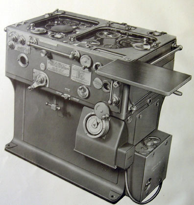
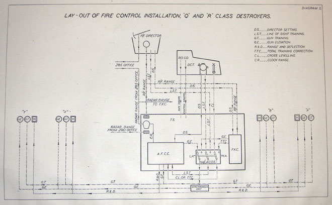
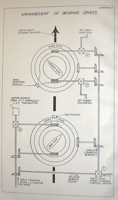
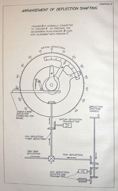
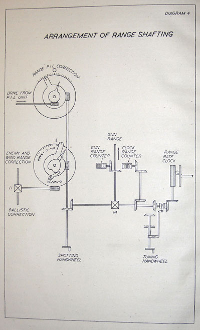
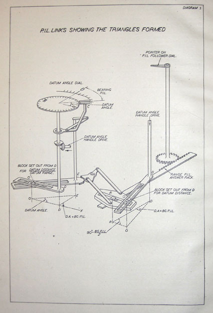
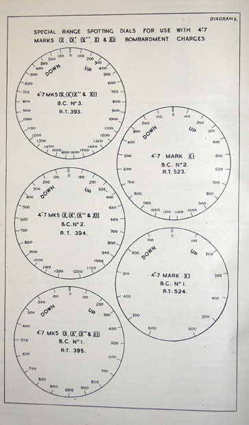
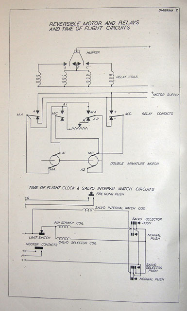

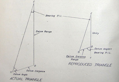
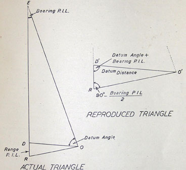